Pass Your Coast Guard Licensing Exams!
Study offline, track your progress, and simulate real exams with the Coast Guard Exams app
Electricity & Electronics - QMED
145 images
Question 1
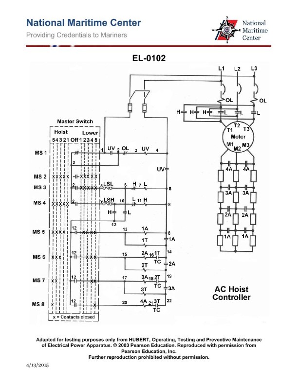
Question: The winch shown in the illustration will operate normally in all speeds in both directions, with the exception that it will not accelerate into 'fifth point' hoist or 'fifth point' lower. What would be a possible cause? Illustration EL-0102
A. master switch contacts ‘MS 8' are welded closed
B. time delay relay '3T' coil is open-circuited
C. master switch contact 'MS 7’ fails to close
D. the contactor '5A' coil is open-circuited
The correct answer is B) time delay relay '3T' coil is open-circuited. The explanation is as follows: The winch illustration EL-0102 indicates that the winch will operate normally in all speeds in both directions, except it will not accelerate into the 'fifth point' hoist or 'fifth point' lower. This suggests an issue with the control system that engages the higher speed settings. A possible cause for this behavior is an open-circuited time delay relay '3T' coil, which is responsible for engaging the higher speed settings. If the '3T' coil is not functioning properly, the winch would be unable to reach the fifth point hoist or lower speeds. The other options are incorrect because they do not directly explain the issue with the winch's inability to reach the fifth point speeds. Master switch contacts 'MS 8' being welded closed, 'MS 7' failing to close, or the '5A' contactor coil being open-circuited would not specifically prevent the winch from accelerating to the fifth point speeds.
Question 30
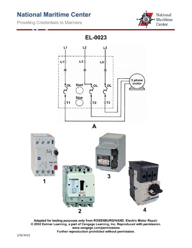
Question: What operational characteristic is associated with the illustrated manual starter circuit for a motor shown in figure "A"? Illustration EL-0023
A. has no low voltage protection and the motor may be damaged if the voltage drops below a certain level
B. incorporates low voltage release because the motor will stop when voltage falls below a certain value and automatically start when normal voltage resumes
C. incorporates low voltage protection because the motor will stop when voltage falls below a certain value but must be manually restarted when normal voltage resumes
D. incorporates low voltage protection because the motor will stop when voltage falls below a certain value and automatically start when normal voltage resumes
The correct answer is A) has no low voltage protection and the motor may be damaged if the voltage drops below a certain level. The illustrated manual starter circuit for a motor shown in figure "A" does not incorporate any low voltage protection. This means that if the voltage supplied to the motor drops below a certain threshold, the motor will continue to run without any automatic shutdown or protection. This could potentially damage the motor if the voltage drops too low for an extended period of time. The other answer choices describe circuits that have some form of low voltage protection, which is not the case for the manual starter circuit shown in figure "A".
Question 32
Question: Which of the following illustrated manual motor starters represents the wiring diagram illustrated in figure "A"? Illustration EL-0023
A. 1
B. 2
C. 3
D. 4
The correct answer is A. The wiring diagram illustrated in figure "A" of the manual motor starter illustration EL-0023 corresponds to the wiring diagram shown in option 1. This is because the diagram in option 1 depicts a straightforward wiring setup for a manual motor starter, with the power supply, overload relay, and motor terminals connected in the appropriate configuration as illustrated in figure "A". The other options do not accurately represent the wiring diagram shown in figure "A" and are therefore incorrect.
Question 34
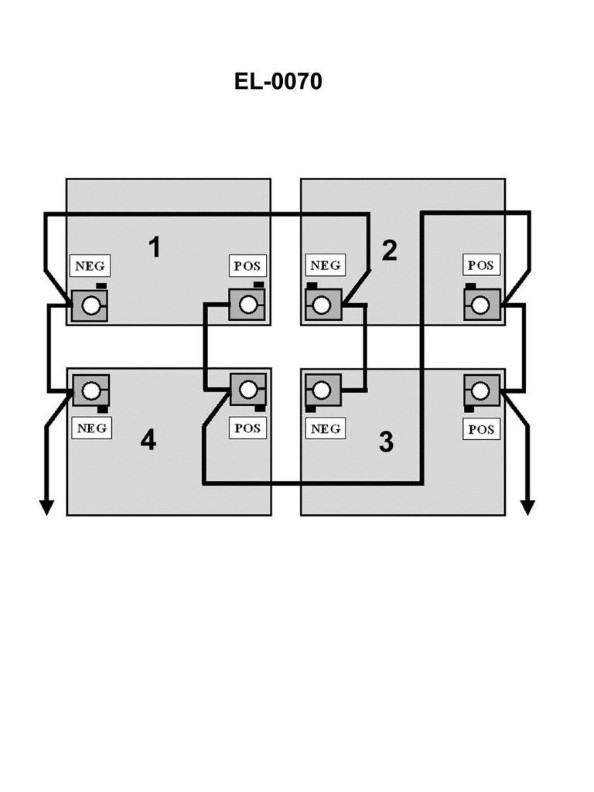
Question: The wet cell storage batteries shown in the illustration are connected in what configuration? Illustration EL-0070
A. series
B. compound
C. tandem
D. parallel
The correct answer is D) parallel. In a parallel configuration, the positive terminals of the batteries are connected together, and the negative terminals are also connected together. This allows each battery to operate independently, with the total current being the sum of the individual battery currents. This is the typical configuration for multiple wet cell storage batteries used to power electrical systems on vessels, as it provides redundancy and allows individual batteries to be charged or replaced without affecting the overall system. The other options are incorrect because: A) series configuration connects the batteries end-to-end, which is not typical for this application; B) compound configuration combines series and parallel connections, which is not the case here; and C) tandem configuration refers to batteries placed one behind the other, which is also not the case in the given illustration.
Question 35
Question: The individual 6 volt lead-acid batteries, when connected as shown in the illustration, as a battery bank would produce how many volts? Illustration EL-0070
A. 6
B. 12
C. 18
D. 24
The correct answer is A) 6 volts. When individual 6-volt lead-acid batteries are connected in parallel, as shown in the illustration EL-0070, the voltage of the battery bank remains at 6 volts. This is because batteries connected in parallel share the same voltage, while the current capacity of the bank increases. The other answer choices are incorrect because: B) 12 volts would be the result of connecting the batteries in series, not parallel; C) 18 volts and D) 24 volts are not possible configurations for a battery bank of 6-volt batteries connected in parallel.
Question 77
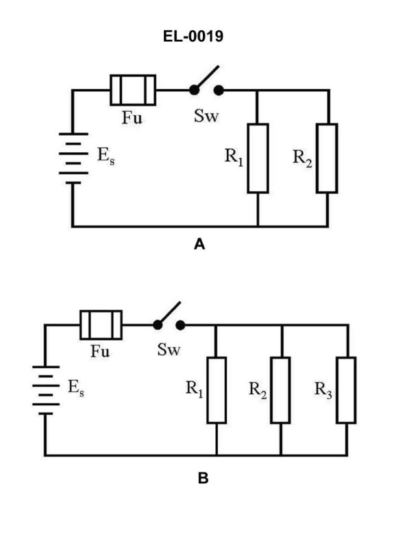
Question: What is the current flow through R1 of the circuit in figure "B" of the illustration with the switch closed if the resistance of R1 is 2 ohms, R2 is 3 ohms and R3 is 6 ohms and the battery voltage is 12 VDC? Illustration EL-0019
A. 2 amps
B. 4 amps
C. 6 amps
D. 12 amps
The correct answer is C) 6 amps. To calculate the current through R1, we can use Ohm's law, which states that current (I) is equal to voltage (V) divided by resistance (R). In this case, the voltage is 12 VDC, and the resistance of R1 is 2 ohms. Plugging these values into the equation, we get: I = V/R = 12V / 2 ohms = 6 amps. The other answer choices are incorrect because: A) 2 amps is too low, as the calculation shows the current is 6 amps. B) 4 amps is too low, as the calculation shows the current is 6 amps. D) 12 amps is too high, as the calculation shows the current is 6 amps.
Question 79
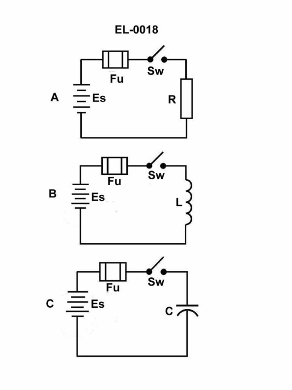
Question: What will be the resulting current when a voltage of 442.7 VDC is applied to a resistance of 1.25 ohms in figure "A" of the illustrated circuit when the switch is closed? Illustration EL-0018
A. 28.25 amps
B. 35.32 amps
C. 354.16 amps
D. 443.62 amps
The correct answer is C) 354.16 amps. This is calculated using Ohm's law, which states that the current (I) in a circuit is equal to the voltage (V) divided by the resistance (R). The formula is I = V/R. Plugging in the values given, we get I = 442.7 V / 1.25 ohms = 354.16 amps. The other answer choices are incorrect because they do not properly apply Ohm's law to the given circuit parameters. Choices A, B, and D do not accurately calculate the current when a 442.7 VDC voltage is applied across a 1.25 ohm resistance.
Question 80
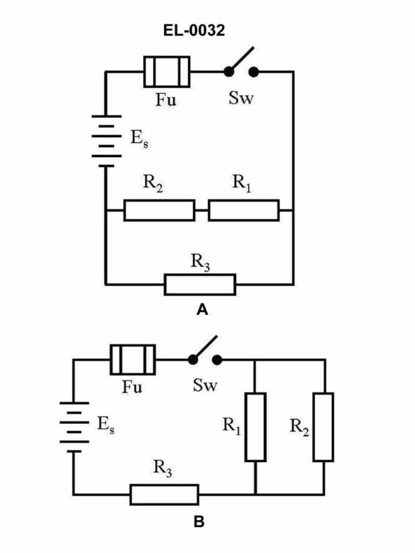
Question: What would be the total current flowing in the circuit shown in figure "B" of the illustration if the source is 30 volts, the resistance of R1 is 10 ohms, R2 is 10 ohms and R3 is 10 ohms, respectively? Illustration EL-0032
A. 1 amp
B. 2 amps
C. 5 amps
D. 15 amps
The correct answer is B) 2 amps. To calculate the total current flowing in the circuit, we can use the formula for total resistance in a parallel circuit: 1/Rtotal = 1/R1 + 1/R2 + 1/R3. Given that R1, R2, and R3 are all 10 ohms, the total resistance is 10/3 ohms. Applying Ohm's law, with a source voltage of 30 volts, the total current in the circuit is 30 volts / (10/3 ohms) = 2 amps. The other options are incorrect because: A) 1 amp is too low, as the calculation shows the total current is 2 amps. C) 5 amps is too high, as the total resistance of 10/3 ohms would not allow for 5 amps of current. D) 15 amps is also too high and not possible given the source voltage and resistance values provided.
Question 82
Question: What will be the resulting current when a voltage of 115 VDC is applied to a resistance of 12 ohms in figure "A" of the illustrated circuit with the switch closed? Illustration EL-0018
A. 1.24 amps
B. 9.58 amps
C. 104.34 amps
D. 127 amps
The correct answer is B) 9.58 amps. The reasoning is based on Ohm's law, which states that the current (I) flowing through a resistor is equal to the voltage (V) divided by the resistance (R). In this case, with a voltage of 115 VDC and a resistance of 12 ohms, the current can be calculated as I = V/R, which equals 115 V / 12 ohms = 9.58 amps. The other options are incorrect because: A) 1.24 amps is too low, as it does not match the calculation. C) 104.34 amps is too high, as it does not match the calculation. D) 127 amps is also too high, as it does not match the calculation.
Question 83
Question: What will be the resulting current when a voltage of 110 VDC is applied to a resistance of 32 ohms in figure "A" of the illustrated circuit when the switch is closed? Illustration EL-0018
A. 0.29 amps
B. 3.44 amps
C. 9.31 amps
D. 142 amps
The correct answer is B) 3.44 amps. This is calculated using Ohm's law, which states that the current (I) is equal to the voltage (V) divided by the resistance (R). In this case, with a voltage of 110 VDC and a resistance of 32 ohms, the current is 110 V / 32 ohms = 3.44 amps. The other answer choices are incorrect because: A) 0.29 amps is too low and does not match the calculation. C) 9.31 amps is too high and does not match the calculation. D) 142 amps is significantly too high and does not match the calculation.
Question 131
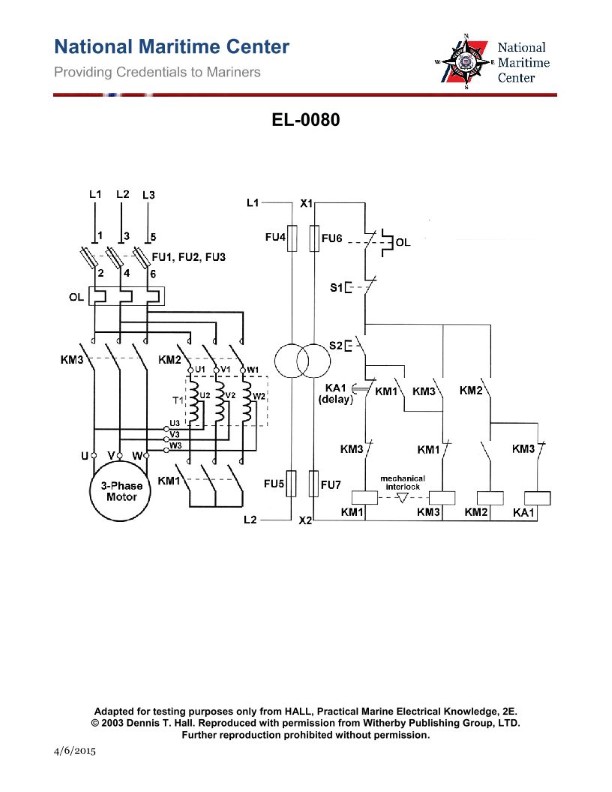
Question: Which device will stop the motor shown in the illustration in case of a short-circuit (high current) motor fault? Illustration EL-0080
A. transformer primary fuses FU4 and FU5
B. disconnect switch fuses FU1, FU2, and FU3
C. transformer secondary fuses FU6 and FU7
D. overload relay heaters and overload relay NC contacts (OL)
The correct answer is B) disconnect switch fuses FU1, FU2, and FU3. In the event of a short-circuit or high current fault in the motor circuit, the disconnect switch fuses FU1, FU2, and FU3 would be the first line of defense to stop the motor. These fuses are positioned before the motor and would quickly open to interrupt the flow of excessive current, protecting the motor from damage. The other options are not correct because: A) the transformer primary fuses FU4 and FU5 are not directly in the motor circuit, C) the transformer secondary fuses FU6 and FU7 would not be able to stop the motor, and D) the overload relay is designed to protect against prolonged overloads, not immediate short-circuit faults.
Question 132
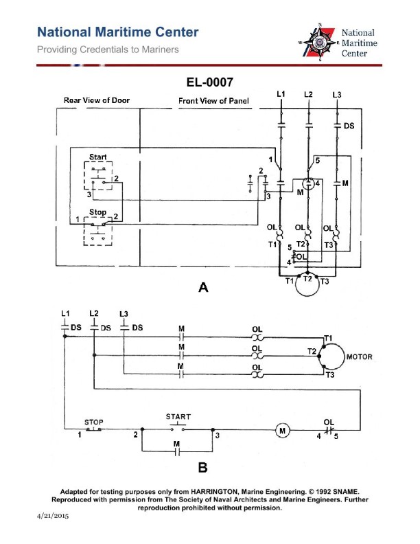
Question: In the illustrated motor controller, the motor fails to start. A voltmeter reading between 1 and 5 reads line voltage, while the voltmeter reading between 2 and 5 reads 0 VAC. What is most likely the problem? Illustration EL-0007
A. an open start switch contact (when pushed in)
B. an open stop switch contact (when not pushed in)
C. an open main contactor "M" coil
D. an overload "OL" relay contact
The correct answer is B) an open stop switch contact (when not pushed in). The reasoning is that with line voltage present between terminals 1 and 5, but 0 VAC between terminals 2 and 5, the issue is likely an open circuit in the stop switch contact. When the stop switch is not pushed in (open contact), it breaks the circuit and prevents the motor from starting, even though line voltage is present. The other options are incorrect because an open start switch (A) would prevent voltage from reaching the motor, an open main contactor coil (C) would also prevent the motor from starting, and an overload relay contact (D) would only open after the motor has already started.
Question 134
Question: The motor starts when the start button in the illustration is pushed, but stops when the button is released. What is most likely the trouble? Illustration EL-0007
A. an open auxiliary "M" contact
B. a corroded contact on the disconnect switch (DS) at 'L3'
C. an open "M" contactor coil
D. an open in the stop button contact
The correct answer is A) an open auxiliary "M" contact. When the start button is pushed, it energizes the "M" contactor coil, which closes the main contacts to start the motor. However, when the start button is released, the "M" contactor coil should remain energized through the auxiliary "M" contact to keep the motor running. If the auxiliary "M" contact is open, the "M" contactor coil will de-energize, causing the motor to stop when the start button is released. The other options are incorrect because: B) a corroded contact on the disconnect switch (DS) at 'L3' would not cause the motor to stop when the start button is released, C) an open "M" contactor coil would prevent the motor from starting in the first place, and D) an open in the stop button contact would not cause the motor to stop when the start button is released.
Question 135
Question: The motor fails to start on an attempted startup. With the start button depressed, a voltmeter reading between 1 and 5, as illustrated in figure "A", indicates line voltage available to the control circuit, what should be your next step in the troubleshooting process? Illustration EL-0007
A. insure that the disconnect switch (DS) is closed
B. test the contactor coil "M" for continuity and replace if necessary
C. test the stop button for continuity and replace if necessary
D. attempt to reset the overload relay and determine the cause of the overload if applicable
The correct answer is D) attempt to reset the overload relay and determine the cause of the overload if applicable. The reasoning is that with a voltmeter reading between 1 and 5 volts, as illustrated in figure "A", it indicates that the line voltage is available to the control circuit. This suggests that the issue is likely not with the power supply, but rather with the control circuit itself. The next logical step in the troubleshooting process would be to check the overload relay, as it may have tripped, preventing the motor from starting. Resetting the overload relay and determining the cause of the overload would be the appropriate next step in the troubleshooting process. The other options are not the correct next step in the troubleshooting process: A) Ensuring the disconnect switch (DS) is closed is not necessary, as the voltmeter reading indicates that the power is available. B) Testing the contactor coil "M" for continuity and replacing it if necessary is not the next logical step, as the issue is likely with the overload relay rather than the contactor. C) Testing the stop button for continuity and replacing it if necessary is also not the next logical step, as the voltmeter reading indicates that the issue is not with the power supply or control circuit wiring.
Question 136
Question: The illustrated motor fails to start and gives a loud hum when the start button is depressed, what should then be your first action? Illustration EL-0007
A. disassemble the motor to fix the centrifugal switch so the start windings will be energized
B. push the stop button to de-energize the "M" coil
C. reset the thermal overload
D. hold the "M" contactor closed by hand while wearing electrical safety gloves to get motor started
The correct answer is B) push the stop button to de-energize the "M" coil. When a motor fails to start and gives a loud hum, it indicates that the motor windings are energized but the rotor is not turning. This is likely due to a fault in the motor or the starting circuit. The best first action is to de-energize the motor by pushing the stop button, which will cut power to the "M" coil and the motor windings. This will prevent further damage to the motor and allow you to diagnose the issue safely. The other options are incorrect because: A) disassembling the motor is not the first step and could further damage the equipment; C) resetting the thermal overload does not address the root cause of the issue; and D) holding the "M" contactor closed manually is unsafe and could lead to electrical shock hazards.

Question 139
Question: If a digital multimeter is set up as shown in figure "A" of the illustration to test a capacitor, what would the display read if the capacitor is shorted? Illustration EL-0213
A. the ohmic value would read very high (OL ohms) and remain at that value
B. the ohmic value would read very low and remain at that value
C. the ohmic value would initially read very low, but over time the ohmic value would gradually rise to an extremely high value (OL ohms)
D. the ohmic value would initially read very high (OL ohms), but over time the ohmic value would gradually drop to an extremely low value
The correct answer is B) the ohmic value would read very low and remain at that value. When a capacitor is shorted, it behaves like a direct connection between the two terminals, resulting in a very low resistance or ohmic value. This is because a shorted capacitor essentially creates a direct path for the current to flow, bypassing the capacitive element. Therefore, the digital multimeter would display a very low ohmic reading that would remain constant, as the shorted capacitor continues to provide a low-resistance path. The other answer choices are incorrect because: A) a shorted capacitor would not read a very high resistance; C) the ohmic value would not gradually rise to an extremely high value; and D) the ohmic value would not initially read very high and then gradually drop to an extremely low value.
Question 141
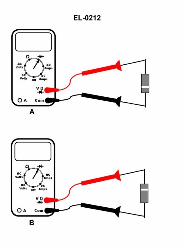
Question: If a digital multimeter is set up as shown in figures "A" and "B" to test a silicon diode, what is the status of the diode if the screen displays OL V when configured as in figure "A" and displays OL V when configured as in figure "B"? Illustration EL-0212
A. diode is operating properly
B. diode is intermittently open
C. diode is open
D. diode is shorted
The correct answer is C) the diode is open. When a digital multimeter is set up to test a silicon diode, as shown in figures "A" and "B", an open diode will display OL V (overload voltage) in both configurations. This indicates that the diode has a break or discontinuity in the circuit, preventing current from flowing through it in either direction. The other options are incorrect because: A) If the diode was operating properly, the multimeter would display a forward voltage drop when configured as in figure "A", and an open circuit (OL V) when configured as in figure "B". B) An intermittently open diode would not consistently display OL V in both configurations. D) A shorted diode would display a very low resistance, not an open circuit.

Question 142
Question: If a digital multimeter is set up as shown in figures "A" and "B" of the illustration, what is the status of the silicon diode if the display reads OL ohms when configured as in figure "A" and reads OL ohms when configured as in figure "B"? Illustration EL-0211
A. the diode is intermittently open
B. the diode is shorted
C. the diode is functioning properly
D. the diode is open
The correct answer is D) the diode is open. When a digital multimeter is set up to measure resistance (configured as in figures "A" and "B" of the illustration), an open diode will display "OL" (overload) in both configurations. This is because an open diode presents an infinite resistance, which the multimeter cannot measure accurately. The other answer choices are incorrect: A) is incorrect because an intermittently open diode would not consistently display "OL" in both configurations. B) is incorrect because a shorted diode would display a very low resistance, not "OL". C) is incorrect because an open diode is not functioning properly.
Question 143
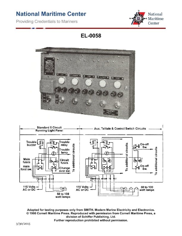
Question: As shown in the illustration, what maintenance would be required of the circuit components? Illustration EL-0058
A. Change out the individual navigation light circuit fuses monthly.
B. Clean the glass surrounding the individual navigation lights as needed.
C. File the points of the buzzer contacts every six months.
D. Take megger readings on the navigation lights quarterly.
The correct answer is B) Clean the glass surrounding the individual navigation lights as needed. The reasoning for this is that navigation lights on vessels are critical safety equipment, and it is important to ensure they are functioning properly. The glass surrounding the lights needs to be kept clean in order to maintain the proper illumination and visibility of the lights. This is a regular maintenance task that should be performed as needed, rather than on a fixed schedule like the other options provided. The other answer choices are incorrect because they do not accurately reflect the proper maintenance requirements for navigation light circuits. Changing fuses monthly, filing buzzer contacts, and taking megger readings are not typical maintenance tasks for these types of circuits.
Question 146
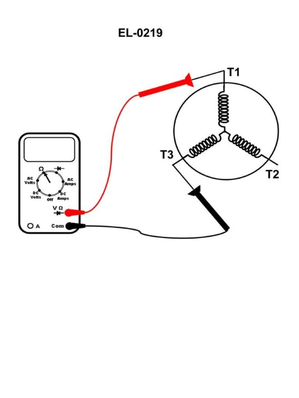
Question: A digital multimeter is set up as shown in the illustration to evaluate the single-circuit stator windings of a squirrel cage induction three-phase motor. The following readings are taken: From T1 to T2 reads "OL" ohms. From T2 to T3 reads "OL" ohms. From T3 to T1 as shown reads "1.6" ohms. What condition is indicated? Illustration EL-0219
A. Phase A (associated with T1
B. are short-circuited. Phase B (associated with T2
C. B
D. and Phase C (associated with T3
The correct answer is A) Phase A (associated with T1) are short-circuited. The reasoning is as follows: 1) The readings show that the resistance between T1-T2 and T2-T3 are both "OL" (open-loop), indicating an open circuit in those phases. 2) However, the reading between T3-T1 is 1.6 ohms, which suggests a short circuit in that phase (Phase A associated with T1). 3) The other options are incorrect because they do not accurately describe the condition indicated by the readings. 4) In summary, the multimeter readings indicate a short circuit in Phase A of the three-phase motor's stator windings.
Question 148
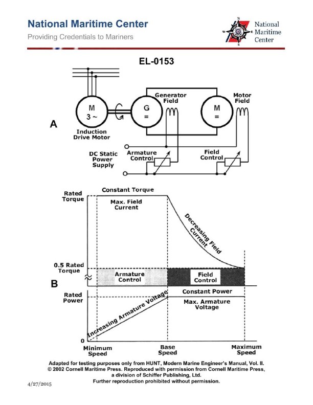
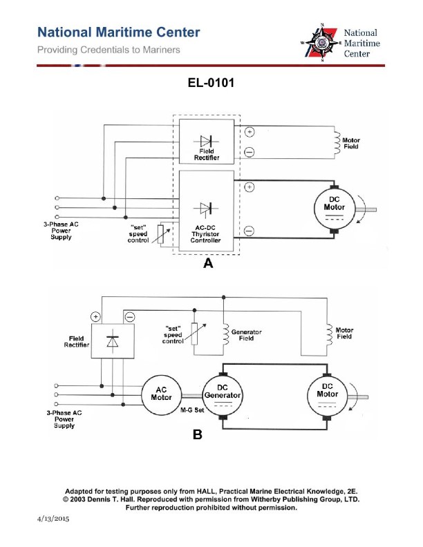
Question: As shown in figure "B" of the illustration, when the DC motor in figure "A" is operating at minimum speed what are the armature and field characteristics? Illustration EL-0153
A. The motor is operating at maximum armature voltage and minimum field current.
B. The motor is operating at minimum armature voltage and maximum field current.
C. The motor is operating at maximum armature voltage and maximum field current.
D. The motor is operating at minimum armature voltage and minimum field current.
The correct answer is B) The motor is operating at minimum armature voltage and maximum field current. When a DC motor is operating at minimum speed, the armature voltage is at its lowest value while the field current is at its maximum. This is because to achieve the minimum speed, the motor controller reduces the armature voltage while increasing the field current. This configuration allows the motor to produce the necessary torque at the lowest possible speed. The other options are incorrect because they do not accurately describe the motor's characteristics at minimum speed. For example, option A would result in maximum speed, while options C and D do not match the expected armature voltage and field current relationship at minimum speed.
Question 149
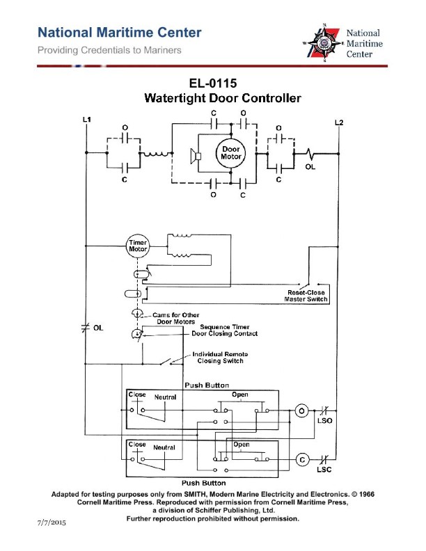
Question: As shown in the illustrated electrically operated watertight door controller, how is the rotation direction of the door motor reversed? Illustration EL-0115
A. reversing the direct current direction through the motor series field and maintaining the same direct current direction through the motor armature
B. reversing the direct current direction through the motor armature and maintaining the same direct current direction through the motor series field
C. reversing the direct current direction through the motor series field and the motor armature
D. reversing the direct current direction through the motor armature and maintaining the same direct current direction through the motor shunt field
The correct answer is B) reversing the direct current direction through the motor armature and maintaining the same direct current direction through the motor series field. To reverse the rotation direction of a DC motor, you need to reverse the direction of the current flowing through the armature. By keeping the current direction through the series field the same, you maintain the same magnetic field, but the reversed armature current will cause the motor to spin in the opposite direction. The other options are incorrect because: A) reversing both the armature and series field would result in the same rotation direction; C) reversing both would also not reverse the direction; and D) the shunt field is not involved in the basic reversing of a DC motor.
Question 150
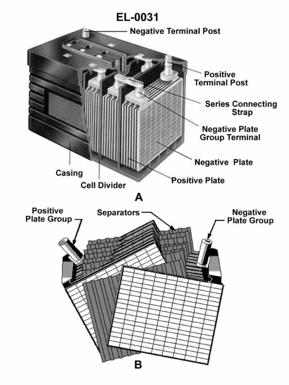
Question: In the illustrated views of a lead-acid battery as shown in figures "A" and "B", what battery component has the sole function of preventing the individual plates in the negative plate group from coming into direct contact with the individual plates in the positive plate group? Illustration EL-0031
A. separators
B. cell dividers
C. casing
D. series connecting straps
The correct answer is A) separators. Separators are the battery components that physically separate the positive and negative plates within each cell, preventing them from coming into direct contact. This is a critical function to ensure the proper operation and safety of the battery. The other options are incorrect because: B) Cell dividers refer to the partitions that separate the individual cells within the battery, not the components that separate the plates within each cell. C) The casing contains and protects the internal battery components, but does not directly prevent plate-to-plate contact. D) The series connecting straps link the cells in series, but do not prevent plate-to-plate contact within each individual cell.
Question 153
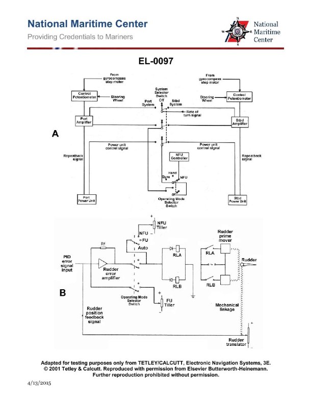
Question: What controls rudder movement when the Operation Selector Switch shown in figure "A" of the illustration is in the "Controller" position? Illustration EL-0097
A. ship's steering wheel
B. non-follow-up controller
C. rate of turn signal
D. gyrocompass
The correct answer is B) non-follow-up controller. When the Operation Selector Switch is in the "Controller" position, the non-follow-up controller is used to control rudder movement. The non-follow-up controller allows for direct, manual control of the rudder without any feedback or position indication, unlike a follow-up controller which provides continuous feedback on the rudder's position. The other options are incorrect because: A) the ship's steering wheel is not used when the selector switch is in the "Controller" position, C) the rate of turn signal does not directly control the rudder, and D) the gyrocompass provides heading information but does not directly control the rudder.
Question 154
Question: As shown in figure "A" of the illustration, fine adjustments such as "rate of turn signal" have no effect on steering stand operation when the 'operation selector switch' is in what position? Illustration EL-0097
A. DIFF
B. HAND
C. GYRO
D. NFU
The correct answer is D) NFU. When the operation selector switch is in the NFU (Non-Follow-Up) position, fine adjustments such as the "rate of turn signal" have no effect on the steering stand operation. In the NFU mode, the steering stand is disconnected from the autopilot or other automatic control systems, and the helm is directly controlling the rudder, making fine adjustments irrelevant. The other options (DIFF, HAND, and GYRO) are incorrect because they involve different steering modes that would be affected by fine adjustments to the system, unlike the NFU mode where the helm has direct manual control.
Question 157
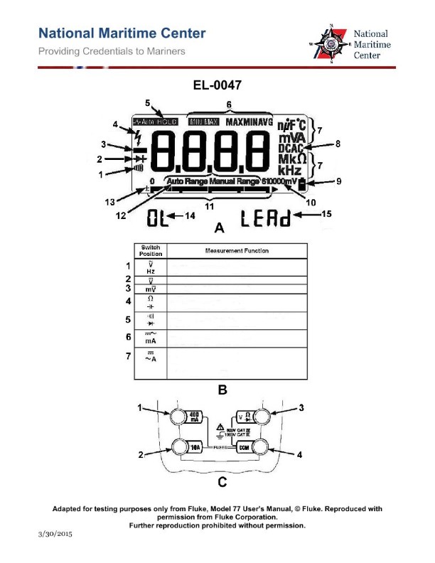
Question: As shown in figure "A" of the illustrated digital multimeter screen, what would be the significance of the symbol indicated by "2" being illuminated? Illustration EL-0047
A. the selector switch is in the resistance position and the meter leads are connected across a PN junction of a transistor
B. the selector switch is in the continuity/diode test position and the secondary function push button is toggled for continuity
C. the selector switch is in the continuity/diode test position and the secondary function push button is toggled for diode
D. the selector switch is in the resistance position and the meter leads are connected across a diode
The correct answer is C) the selector switch is in the continuity/diode test position and the secondary function push button is toggled for diode. The illumination of the "2" symbol on the digital multimeter screen indicates that the meter is in the diode test mode. In this mode, the multimeter applies a small voltage across the test leads and measures the voltage drop, which can be used to test the condition of a diode. This is the secondary function of the multimeter, which is accessed by toggling the secondary function push button. The other answer choices are incorrect because they do not accurately describe the conditions indicated by the "2" symbol. Option A is incorrect as the resistance measurement mode does not have a specific symbol like "2". Option B is incorrect as the continuity test mode would be indicated by a different symbol. Option D is incorrect as the resistance measurement mode does not have a specific diode testing function.
Question 196
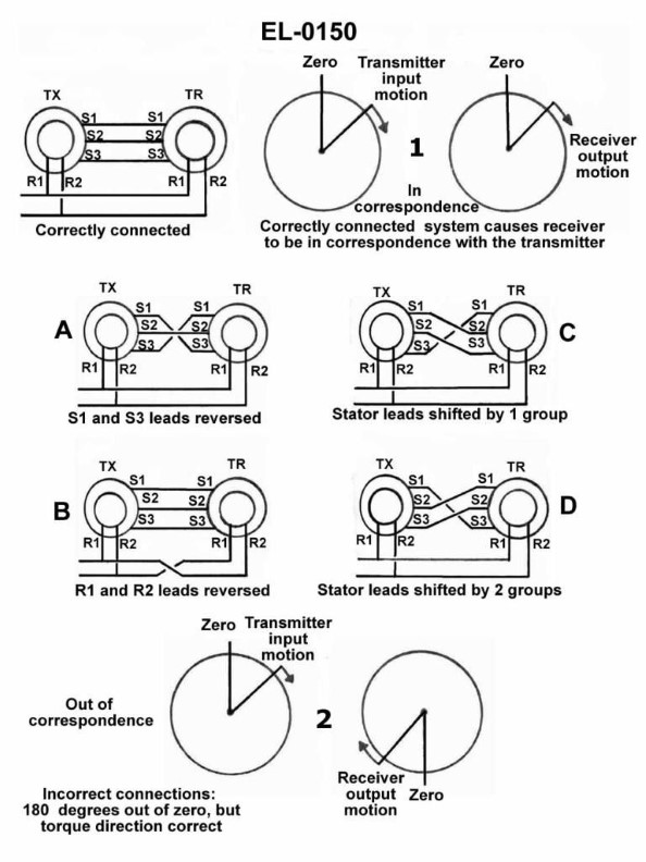
Question: As shown in figure "1" of the illustration, a correctly connected synchronous transmission causes the receiver to be in correspondence with the transmitter. If the receiver is out of correspondence, 180 degrees out of zero, but the torque direction is correct as shown in figure "2", what figure shows the incorrect connections responsible for this condition? Illustration EL-0150
A. A
B. B
C. C
D. D
The correct answer is B. When the receiver is 180 degrees out of phase with the transmitter, it indicates that the connections are reversed. Figure B in the illustration shows the incorrect connections responsible for this condition, as it depicts the polarity of the connections being reversed compared to the correct configuration shown in Figure 1. The other options are incorrect because: A) does not show the reversed polarity that would cause the 180-degree phase shift. C) and D) do not depict the specific configuration that would lead to the receiver being 180 degrees out of phase with the transmitter.
Question 197
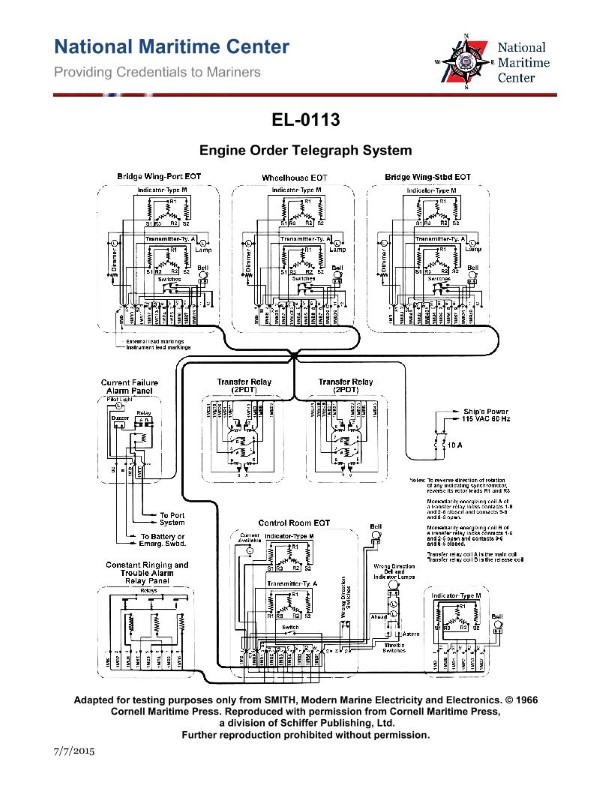
Question: As shown in the illustrated wiring diagram for an engine order telegraph system, what statement concerning the constant ringing and trouble alarm is true? Illustration EL-0113
A. The constant ringing and trouble alarm sounds when there is a power loss from the 115 VAC power supply to the system.
B. The constant ringing and trouble alarm sounds when the transmitter rotor and corresponding indicator rotor are in correspondence.
C. The constant ringing and trouble alarm sounds when the acknowledge handle and indicator arrow are not on the same order.
D. The constant ringing and trouble alarm sounds when there is a power loss from the battery or emergency switchboard as appropriate.
The correct answer is C. The constant ringing and trouble alarm sounds when the acknowledge handle and indicator arrow are not on the same order. This is correct because the engine order telegraph system is designed to provide clear and reliable communication between the bridge and the engine room. The constant ringing and trouble alarm is a safety feature that alerts the operator when there is a discrepancy between the acknowledge handle and the indicator arrow, indicating a potential miscommunication or error in the system. The other options are incorrect because they do not accurately describe the purpose and function of the constant ringing and trouble alarm in this system.
Question 198
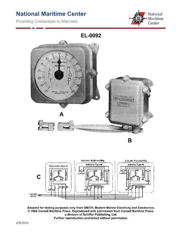
Question: If it is required that the coils 'R1-R2-R3' in the indicator of figure "A", turn opposite to those in the transmitter, as shown in the illustration, what action should be taken? Illustration EL-0092
A. Interchange leads 'R1' and 'R3'.
B. Interchange leads 'R2' and 'R3'.
C. Reverse the 60 Hz supply connections to 'S1' and 'S2'.
D. No action is needed.
The correct answer is A) Interchange leads 'R1' and 'R3'. The reasoning is that for the indicator in figure "A" to turn in the opposite direction of the transmitter, the coils 'R1-R2-R3' in the indicator need to be connected in the reverse order compared to the transmitter. Interchanging the leads 'R1' and 'R3' will achieve this, as it will reverse the direction of the coils in the indicator. The other options are incorrect because B) interchanging 'R2' and 'R3' would not reverse the direction, C) reversing the 60 Hz supply connections would not address the issue with the coil order, and D) some action is needed to correct the coil orientation.
Question 202
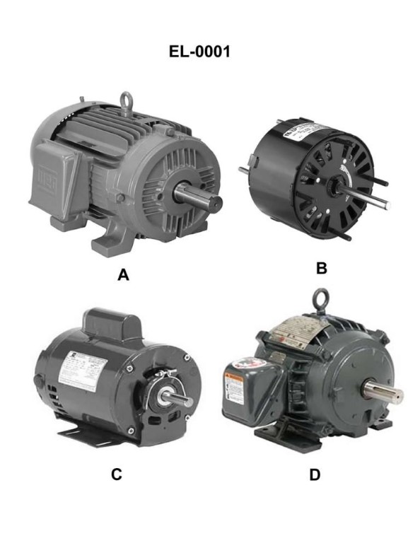
Question: Which of the illustrated motors has a totally enclosed, fan-cooled (TEFC) motor enclosure? Illustration EL-0001
A. A
B. B
C. C
D. D
The correct answer is A. The totally enclosed, fan-cooled (TEFC) motor enclosure is designed to prevent the ingress of dust, dirt, and moisture, while using a fan to draw air across the motor to provide cooling. This type of enclosure is well-suited for marine applications where the motor may be exposed to the elements. Based on the illustration EL-0001, option A depicts the TEFC motor enclosure. The other options (B, C, and D) may represent different types of motor enclosures, such as open drip-proof or splash-proof, which are not as well-protected from the marine environment as the TEFC enclosure.
Question 203
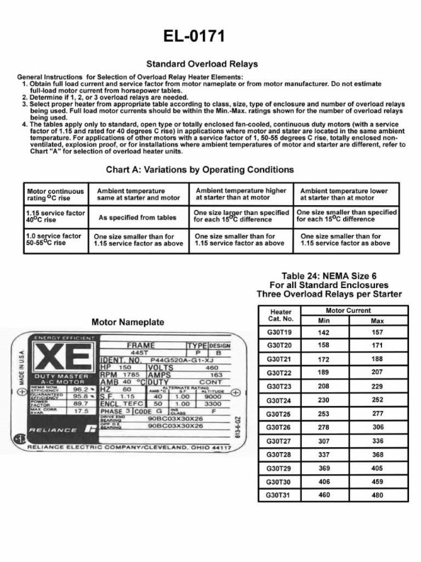
Question: As shown in figure “A" of the illustrated motor nameplate, what is the service factor at sea level? Illustration EL-0171
A. 1.00
B. 1.15
C. 17.5
D. 89.7
The correct answer is B) 1.15. The service factor, as shown in figure "A" of the illustrated motor nameplate, represents the multiplier that can be applied to the motor's rated horsepower to determine the maximum safe operating load for the motor. A service factor of 1.15 indicates that the motor can be safely operated at up to 115% of its rated horsepower without exceeding the motor's design limits. The other answer choices are incorrect because: A) 1.00 would represent the motor's rated horsepower, not the service factor; C) 17.5 is not a typical service factor value; and D) 89.7 does not correspond to the information provided in the illustration.
Question 207
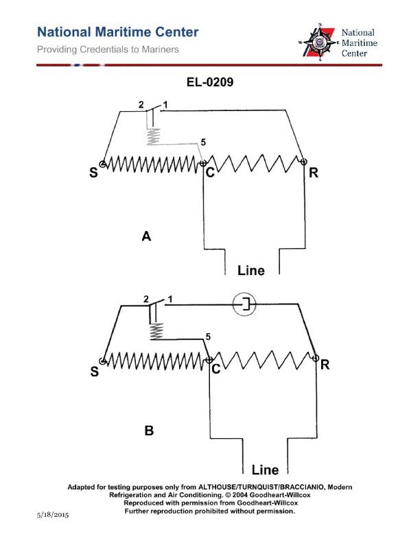
Question: What type of motor is illustrated by the schematic of figure "B" of the illustration and what type of starting relay is used? Illustration EL-0209
A. resistive start, induction run (split phase) motor using a hot wire starting relay
B. resistive start, induction run (split phase) motor using a current starting relay
C. resistive start, induction run (split phase) motor using a potential starting relay
D. capacitor start, induction run motor using a potential starting relay
The correct answer is D) capacitor start, induction run motor using a potential starting relay. This is correct because the schematic in figure "B" of illustration EL-0209 depicts a capacitor start, induction run motor configuration. The capacitor in the starting winding circuit provides the necessary phase shift to get the motor started, and a potential starting relay is used to engage the starting winding. The other options are incorrect because they do not match the motor configuration shown in the illustration. Options A, B, and C describe split-phase induction motors, which have a different starting winding arrangement than a capacitor start motor.
Question 209
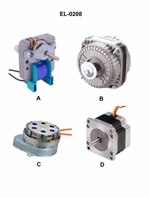
Question: Which of the pictured motors is a square core shaded pole motor used to drive very small electrical loads and is non-reversible? Illustration EL-0208
A. A
B. B
C. C
D. D
The correct answer is B. The square core shaded pole motor is a type of small, non-reversible electric motor commonly used to drive very small electrical loads. This motor design is typically found in appliances, fans, and other low-power devices. The illustration EL-0208 shows several different motor types, and option B depicts the characteristic square core and single-phase design of a shaded pole motor. The other options (A, C, and D) represent different motor types that do not match the specific characteristics of a square core shaded pole motor as described in the question.
Question 212
Question: Which of the illustrated motors has a totally enclosed motor enclosure? Illustration EL-0001
A. A
B. B
C. C
D. D
The correct answer is D. The totally enclosed motor enclosure is designed to prevent the ingress of external air into the motor, making it suitable for use in hazardous or wet environments. This type of enclosure is typically required for motors used in marine applications, such as those found on vessels, to ensure safety and prevent the risk of fire or explosion. The other options (A, B, and C) likely represent different motor enclosure types, such as open, splash-proof, or weather-protected, which may not provide the same level of protection as the totally enclosed motor enclosure.
Question 214
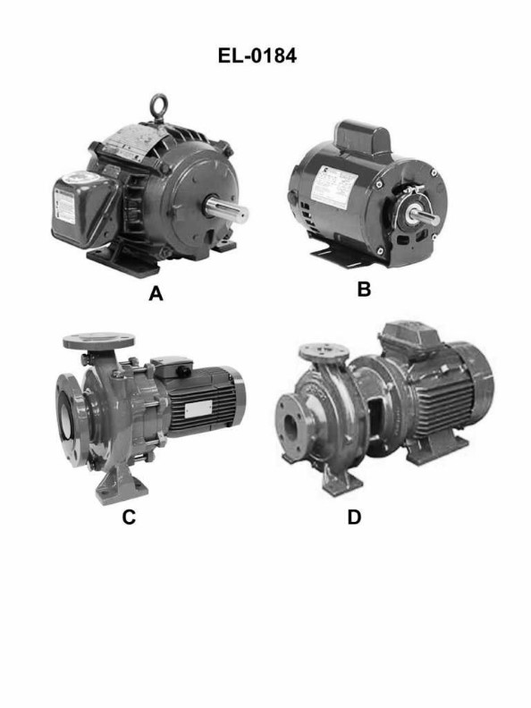
Question: Which of the following motors has a frame configuration for resilient base mounting? Illustration EL-0184
A. A
B. B
C. C
D. D
The correct answer is B. The frame configuration described in the illustration EL-0184 is for a resilient base mounting, which is a common feature of electric motors designed for marine applications. This type of mounting helps isolate the motor from the vibrations and movements of the vessel, preventing premature wear and tear on the motor. The other options (A, C, and D) likely represent different motor frame configurations that may be suitable for other applications, but do not specifically indicate the resilient base mounting required for marine use.
Question 216
Question: What type of motor enclosure is utilized for the motor labeled "A" of the illustration? Illustration EL-0001
A. Totally enclosed
B. Totally enclosed, fan-cooled
C. Open, drip-proof
D. Open
The correct answer is B) Totally enclosed, fan-cooled. The motor labeled "A" in the illustration EL-0001 is required to have a totally enclosed, fan-cooled enclosure, as per the regulations for motor enclosures on commercial vessels. This type of enclosure provides protection from the elements while also allowing for active cooling of the motor, which is necessary for its safe and reliable operation on a marine vessel. The other options are incorrect because: A) Totally enclosed does not provide active cooling, C) Open, drip-proof does not provide sufficient protection from the marine environment, and D) Open is not an appropriate enclosure for a motor on a commercial vessel.
Question 223
Question: What power would be consumed by the series resistor in the circuit shown in the illustration if the source is 30 volts, the resistance for R1 is 10 ohms, R2 is 10 ohms and R3 is 10 ohms? Illustration EL-0032
A. 10 watts
B. 30 watts
C. 40 watts
D. 60 watts
The correct answer is C) 40 watts. To calculate the power consumed by the series resistor, we need to use the formula P = V^2/R, where P is the power, V is the voltage, and R is the resistance. Given the information: - Source voltage (V) = 30 volts - Resistance for R1, R2, and R3 = 10 ohms each Since the resistors are in series, the total resistance is the sum of the individual resistances: R_total = R1 + R2 + R3 = 10 + 10 + 10 = 30 ohms. Plugging the values into the formula, we get: P = V^2/R = (30 V)^2 / 30 ohms = 900 watts / 30 ohms = 40 watts. The other options are incorrect because: A) 10 watts is too low, as the total power consumed in the series circuit is 40 watts. B) 30 watts is too low, as the total power consumed in the series circuit is 40 watts. D) 60 watts is too high, as the total power consumed in the series circuit is 40 watts.
Question 225
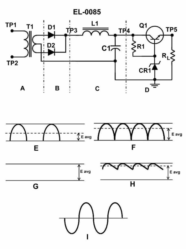
Question: Assuming a standard 60 Hz input to the circuit shown in the illustration, what would be the ripple frequency? Illustration EL-0085
A. 30 Hz
B. 60 Hz
C. 90 Hz
D. 120 Hz
The correct answer is D) 120 Hz. The ripple frequency in a full-wave rectified circuit with a 60 Hz input is twice the line frequency, which is 120 Hz. This is because in a full-wave rectifier, the output alternates between the positive and negative half-cycles of the input waveform, effectively doubling the frequency. The other options are incorrect because 30 Hz is half the line frequency, 60 Hz is the line frequency, and 90 Hz is not related to the input frequency in a full-wave rectified circuit.
Question 226
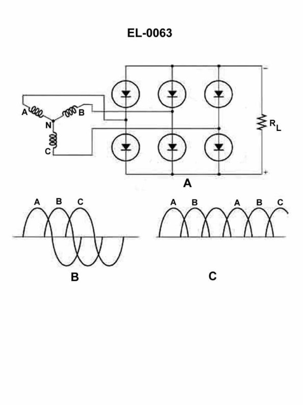
Question: What does the drawing in the illustrated circuit represent? Illustration EL-0063
A. a six phase half wave rectifier
B. a three phase full wave rectifier
C. a single phase full wave rectifier
D. a three phase half wave rectifier
The correct answer is B) a three phase full wave rectifier. The illustration EL-0063 represents a three phase full wave rectifier circuit, which is commonly used in marine electrical systems to convert three-phase alternating current (AC) to direct current (DC). In a three phase full wave rectifier, all three phases of the AC input are utilized, resulting in a smoother and more stable DC output compared to a single phase or half wave rectifier. The other options are incorrect because: A) A six phase half wave rectifier would have a different circuit configuration. C) A single phase full wave rectifier would only have two input phases, not three. D) A three phase half wave rectifier would not utilize all three phases of the AC input.
Question 227
Question: What is the direction of electron current through the load resistor in the circuit shown in the illustration? Illustration EL-0085
A. Always from point "TP5" to the grounded end.
B. Always from the grounded end to point "TP5".
C. It depends on the instantaneous polarity at "T1".
D. It cannot be determined without a directional ammeter.
The correct answer is B) Always from the grounded end to point "TP5". In a simple series circuit with a DC power source, the direction of electron current flow is always from the negative terminal of the power source, through the load resistor, and back to the positive terminal. Since the grounded end of the circuit represents the negative terminal, the electron current will flow from the grounded end to point "TP5", which is connected to the positive terminal. The other options are incorrect because: A) the current does not always flow from "TP5" to the grounded end, B) is the correct answer, C) the direction of current does not depend on the instantaneous polarity at "T1", and D) the direction of current can be determined without a directional ammeter based on the basic principles of series circuits.
Question 228
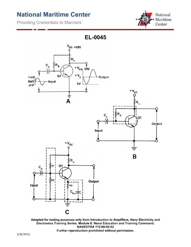
Question: In figure "A" of the illustrated circuit, what is the main purpose of the bias resistor Rb? Illustration EL-0045
A. to eliminate the need for an emitter-base battery for establishing reverse emitter-base bias
B. to eliminate the need for a collector-emitter battery for establishing reverse collector-emitter bias
C. to eliminate the need for a collector-emitter battery for establishing forward collector-emitter bias
D. to eliminate the need for an emitter-base battery for establishing forward emitter-base bias
The correct answer is D. The main purpose of the bias resistor Rb in the illustrated circuit (figure "A") is to eliminate the need for an emitter-base battery for establishing forward emitter-base bias. The bias resistor Rb provides a path for the base current, allowing the transistor to operate in the active region by establishing the necessary forward emitter-base bias without the need for an additional emitter-base battery. The other options are incorrect because they do not accurately describe the purpose of the bias resistor Rb in this circuit. Option A and B are incorrect as the bias resistor is not used to establish reverse biases. Option C is incorrect as the bias resistor is used to establish forward, not reverse, collector-emitter bias.
Question 230
Question: What type of feedback is featured in the transistor amplifier shown in figure "B" of the illustration assuming that the phase relationship between input and output is identical to the transistor amplifier shown in figure "A"? Illustration EL-0045
A. positive feedback also known as degenerative feedback
B. positive feedback also known as regenerative feedback
C. negative feedback also known as regenerative feedback
D. negative feedback also known as degenerative feedback
The correct answer is D) negative feedback also known as degenerative feedback. The explanation is as follows: 1. Confirm which answer is correct: The correct answer is D) negative feedback also known as degenerative feedback. 2. Explain the reasoning or regulation that makes it correct: In a transistor amplifier, the phase relationship between the input and output signals is crucial in determining the type of feedback. When the phase relationship is identical to the transistor amplifier shown in figure "A", it indicates that the feedback is negative or degenerative, which means the output signal is 180 degrees out of phase with the input signal. 3. Explain why the other options are incorrect: Options A and B are incorrect because positive feedback, also known as regenerative feedback, is not present in this case. Option C is incorrect because negative feedback is not considered "regenerative" feedback.
Question 231
Question: Which section of the circuit shown in the illustration smoothes out highest degree of pulsations? Illustration EL-0085
A. A
B. B
C. C
D. D
The correct answer is C. The section of the circuit that smoothes out the highest degree of pulsations is the section labeled C, which contains a filter capacitor. The filter capacitor helps to reduce the ripple or pulsations in the output voltage by storing and releasing energy to stabilize the voltage. This is a key component in power supply circuits to provide a smooth, consistent output. The other sections (A, B, D) do not contain the necessary filtering components to achieve the same degree of pulsation reduction as the filter capacitor in section C.
Question 232
Question: In the regulated DC power supply illustrated, what is the function of section "B"? Illustration EL-0085
A. half wave rectification
B. quarter wave rectification
C. full wave rectification
D. short wave rectification
The correct answer is C) full wave rectification. The function of section "B" in the regulated DC power supply illustrated in EL-0085 is to perform full wave rectification. Full wave rectification converts both the positive and negative half-cycles of the AC input into positive half-cycles, resulting in a more stable and continuous DC output. The other answer choices are incorrect because half wave rectification only uses one half of the AC cycle, quarter wave rectification is not a common technique, and short wave rectification is not a standard term in this context.
Question 234
Question: What is the function of section "D" of the circuit shown in the illustration? Illustration EL-0085
A. a voltage transformer
B. a rectifier
C. a voltage regulator
D. a filter
The correct answer is C) a voltage regulator. The function of section "D" in the circuit shown in the illustration EL-0085 is to act as a voltage regulator. A voltage regulator is a device that maintains a constant output voltage regardless of changes in the input voltage or load conditions. This is an essential component in electrical circuits to ensure stable and consistent power supply, which is crucial for the proper functioning of various electrical and electronic systems. The other options, A) a voltage transformer and B) a rectifier, are not the correct functions of section "D" in this circuit. A voltage transformer is used to step up or step down the voltage, while a rectifier converts alternating current (AC) to direct current (DC). Neither of these functions directly matches the role of a voltage regulator in the given circuit.
Question 237
Question: The component labeled 'CR1' in the circuit shown in the illustration serves what functional purpose? Illustration EL-0085
A. it rectifies the varying voltage from the collector of 'Q1'
B. it varies its anode/cathode polarity depending on 'RL' current
C. it acts as a low capacitive reactance to smooth ripple
D. it establishes a constant reference voltage for the base of 'Q1'
The correct answer is D) it establishes a constant reference voltage for the base of 'Q1'. The component labeled 'CR1' in the circuit shown is likely a Zener diode, which is used to maintain a constant reference voltage for the base of transistor 'Q1'. This reference voltage is necessary to ensure proper biasing and operation of the transistor amplifier circuit. The other answer choices are incorrect because: A) a rectifier is not the function of a Zener diode, B) a Zener diode does not vary its polarity based on load current, and C) a Zener diode is not used to smooth ripple, but rather to establish a constant voltage reference.
Question 238
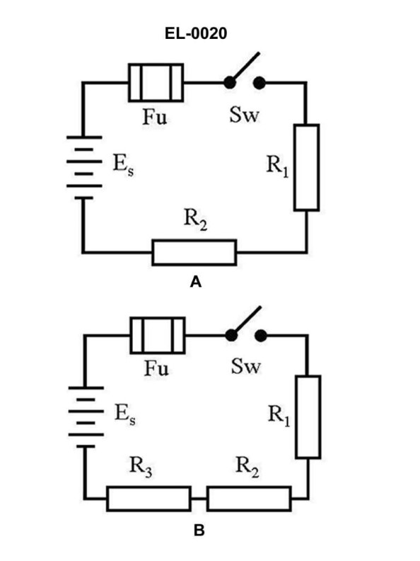
Question: What is the total resistance of figure "B" of the illustrated circuit if the resistance of R1 is 3 ohms, R2 is 4 ohms, and R3 is 5 ohms? Illustration EL-0020
A. 0.5 ohms
B. 1.28 ohms
C. 1.5 ohms
D. 12 ohms
The correct answer is D) 12 ohms. The total resistance of the circuit in figure "B" is the sum of the individual resistances R1, R2, and R3. Since R1 is 3 ohms, R2 is 4 ohms, and R3 is 5 ohms, the total resistance is the sum of these three values, which is 3 + 4 + 5 = 12 ohms. The other answer choices are incorrect because they do not accurately represent the total resistance of the circuit. Option A) 0.5 ohms is too low, option B) 1.28 ohms is too low, and option C) 1.5 ohms is too low. The correct answer, as per the information provided in the illustration and question, is 12 ohms.
Question 240
Question: Which of the following statements is correct for the illustrated circuit in figure "B"? Illustration EL-0020
A. 'R1', 'R2', and 'R3' are connected in parallel.
B. The total resistance equals 1/R1 + 1/R2 + 1/R3.
C. The voltages measured across 'R1', 'R2', and 'R3' are equal.
D. 'R1', 'R2', and 'R3' are connected in series.
The correct answer is D) 'R1', 'R2', and 'R3' are connected in series. This is correct because in a series circuit, the components are connected end-to-end, forming a single path for the current to flow through. The current is the same through each component, and the total resistance is the sum of the individual resistances (R1 + R2 + R3). The other options are incorrect because: A) In a parallel circuit, the resistors are connected to the same two points, and the total resistance is the reciprocal of the sum of the reciprocals of the individual resistances. B) This formula applies to parallel circuits, not series circuits. C) In a series circuit, the voltages across individual resistors are not necessarily equal.
Question 254
Question: What is the name of the DC motor speed control method utilized as shown in figure "B" of the illustration? Illustration EL-0101
A. Burmeister-Wain
B. Atlas-Copco
C. Ward-Leonard
D. Sperry-Rand
The correct answer is C) Ward-Leonard. The Ward-Leonard method is a speed control system for DC motors that uses a generator and a series-connected field rheostat to control the motor's field current and thereby its speed. This method was commonly used for DC motor speed control in the early to mid-20th century, including in various marine applications like those found on US Coast Guard vessels. The other options are incorrect because they do not refer to a DC motor speed control method. Burmeister-Wain, Atlas-Copco, and Sperry-Rand are the names of companies or products, not the specific speed control technique depicted in the illustration.
Question 256
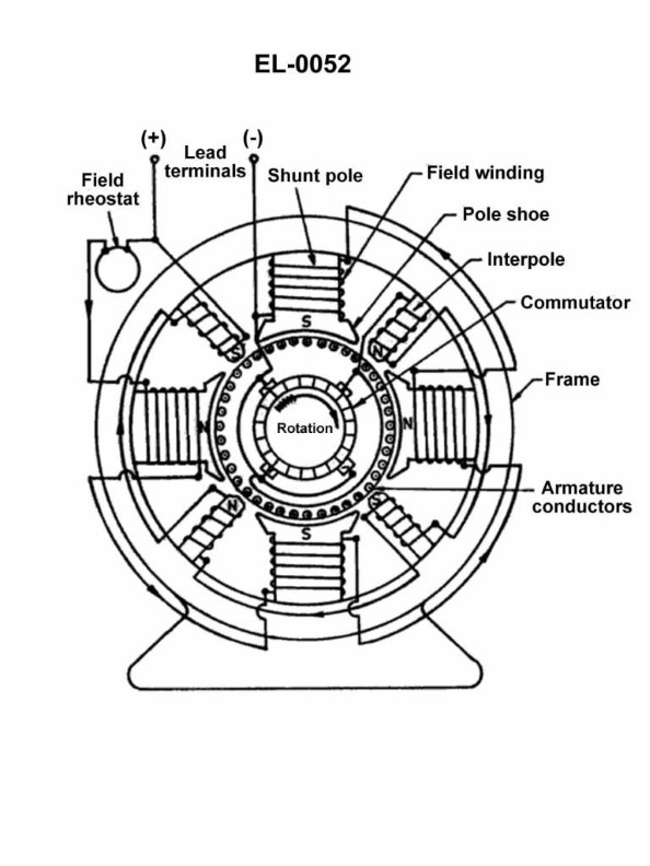
Question: As shown in the illustrated DC machine which is configured as a generator, what is the purpose of the interpoles? Illustration EL-0052
A. strengthen the main field above and beyond the capability of the main field poles
B. counteract armature reaction to maintain the brushes in the neutral plane to minimize brush sparking
C. provide residual magnetism to facilitate an output by means of self-excitation
D. statically balance the stator for uniform weight distribution
The correct answer is B) counteract armature reaction to maintain the brushes in the neutral plane to minimize brush sparking. Interpoles in a DC generator are used to counteract the effects of armature reaction, which is the distortion of the main magnetic field caused by the current flowing in the armature windings. This distortion can cause the brushes to move away from the neutral plane, leading to increased brush sparking. The interpoles create a magnetic field that opposes the armature reaction, helping to keep the brushes in the neutral plane and reduce brush sparking. The other options are incorrect because: A) the main field poles, not the interpoles, are responsible for the main magnetic field; C) residual magnetism is provided by the field windings, not the interpoles; and D) the interpoles do not have any function related to the static balance of the stator.
Question 268
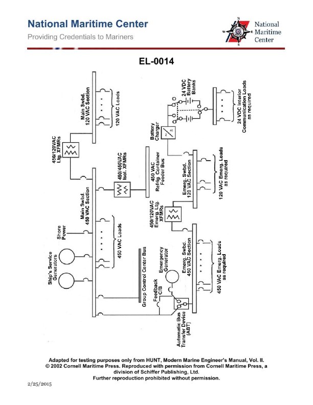
Question: What is a purpose of the automatic bus transfer device shown in the illustration? Illustration EL-0014
A. Provide power to the 450 VAC emergency bus from the emergency generator in the emergency mode.
B. Provide power to the 450 VAC emergency bus from the 450 VAC main bus in the emergency mode.
C. Provide power to the 450 VAC main bus from the 450 VAC emergency bus in the emergency mode.
D. Provide power to the 450 VAC main bus from the emergency generator in the emergency mode.
The correct answer is A) Provide power to the 450 VAC emergency bus from the emergency generator in the emergency mode. The automatic bus transfer device is used to automatically switch the power source for the 450 VAC emergency bus from the main 450 VAC bus to the emergency generator in the event of a power failure. This ensures that essential systems and equipment connected to the emergency bus continue to receive power during an emergency, as required by maritime regulations for vessel safety and operability. The other answer choices are incorrect because they do not accurately describe the purpose of the automatic bus transfer device as shown in the illustration.
Question 275
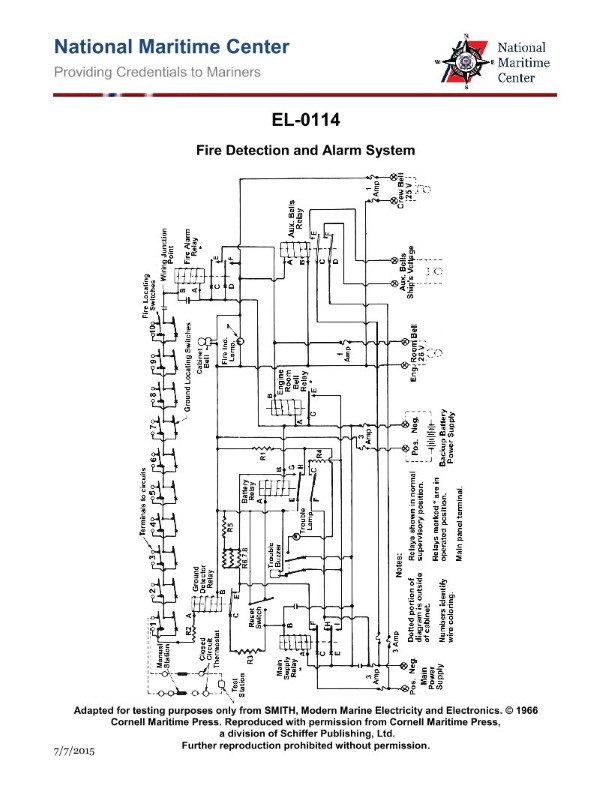
Question: Concerning the illustrated fire detection and alarm system, what statement is true concerning the wiring between zones? Illustration EL-0114
A. The zones are all connected in series by means of the ground locating switches only.
B. The zones are all connected in series by means of the fire locating switches and the ground locating switches.
C. The zones are all connected in parallel by means of the fire locating switches and the ground locating switches.
D. The zones are all connected in series by means of the fire locating switches only.
The correct answer is B) The zones are all connected in series by means of the fire locating switches and the ground locating switches. This is the correct answer because in a typical fire detection and alarm system, the zones are connected in series through both the fire locating switches and the ground locating switches. This allows the system to detect fires and ground faults, which are crucial for safety and proper operation. The other options are incorrect because A) only mentions the ground locating switches, C) describes a parallel connection, and D) only includes the fire locating switches, which does not accurately represent the wiring between the zones.

Question 277
Question: As shown in the illustrated wound-rotor induction motor, how is the direction of rotation of the motor reversed? Illustration EL-0148
A. Any two of the "T1, T2, and T3" leads are reversed only.
B. Any two of the "M1, M2, and M3" leads are reversed only.
C. Any two of the "T1, T2, and T3" leads are reversed and any of the two "M1, M2, and M3" leads must be reversed as well.
D. It is not possible to change the direction of rotation of a wound-rotor induction motor.
The correct answer is A) Any two of the "T1, T2, and T3" leads are reversed only. In a wound-rotor induction motor, the direction of rotation can be reversed by reversing any two of the three "T1, T2, and T3" leads that are connected to the rotor windings. Reversing these two leads changes the direction of the rotating magnetic field, which in turn reverses the direction of the motor's rotation. The other options are incorrect because: B) Reversing the "M1, M2, and M3" leads (which are connected to the stator windings) will not reverse the direction of rotation. C) Reversing both the "T1, T2, and T3" and the "M1, M2, and M3" leads is unnecessary to reverse the direction of rotation. D) It is possible to change the direction of rotation of a wound-rotor induction motor by reversing two of the rotor winding leads.
Question 282
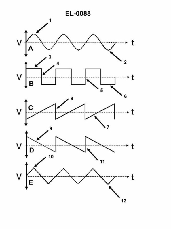
Question: Which of the waveshapes shown in the illustration is termed a ramp or sawtooth wave? Illustration EL-0088
A. A
B. B
C. C
D. E
The correct answer is C. The waveform labeled C in the illustration EL-0088 is termed a ramp or sawtooth wave. This type of waveform has a linear rise followed by a sudden drop, creating a shape resembling the teeth of a saw. The other options are incorrect because: A) is a sine wave, B) is a square wave, and D) is a pulse wave - none of which have the characteristic ramp or sawtooth shape of the correct answer, C.
Question 286
Question: Which line in figure "B" shown in the illustration represents the trailing edge of the wave? Illustration EL-0088
A. 3
B. 4
C. 5
D. 6
The correct answer is B) 4. The line labeled 4 in the illustration represents the trailing edge of the wave. This is the point where the wave's energy begins to dissipate and the wave transitions from the crest to the trough. The other labeled lines in the figure do not correspond to the trailing edge of the wave. The trailing edge is an important concept in navigational situations, as it helps mariners understand the motion and characteristics of waves, which is crucial for safe operations, especially in coastal areas or during heavy weather conditions.
Question 289
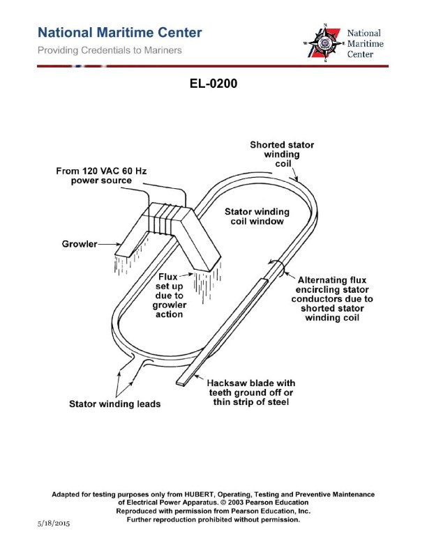
Question: In using a portable growler for the purpose of locating a shorted stator coil in an AC motor as shown in the illustration, what statement is true as the feeler is moved from slot to slot around the stator? Illustration EL-0200
A. The feeler will vibrate in synchronism with the 60 Hz AC power source and produce a growling noise when the feeler is moved over a slot which does NOT contain a shorted coil.
B. The feeler will vibrate in synchronism with the 60 Hz AC power source and produce a growling noise when the feeler is moved over a slot containing an open coil.
C. The feeler will remain motionless with NO vibration or noise when the feeler is moved over a slot containing a shorted coil.
D. The feeler will vibrate in synchronism with the 60 Hz AC power source and produce a growling noise when the feeler is moved over a slot containing a shorted coil.
The correct answer is D. The feeler will vibrate in synchronism with the 60 Hz AC power source and produce a growling noise when the feeler is moved over a slot containing a shorted coil. This is because a shorted stator coil creates a localized magnetic field that interacts with the alternating current in the feeler, causing it to vibrate and produce a distinctive growling noise. The other options are incorrect because: A) The vibration and noise occur when the feeler is over a shorted coil, not a non-shorted coil. B) An open coil would not produce the same effect as a shorted coil. C) The feeler does not remain motionless when over a shorted coil, but rather vibrates and produces a growling noise.
Question 302
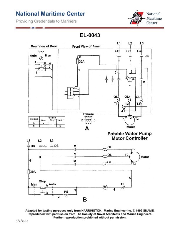
Question: In the illustration shown, what type of protection is provided to the potable pump drive motor? Illustration EL-0043
A. magnetic overload protection and low voltage protection
B. thermal overload protection and low voltage protection
C. magnetic overload protection and low voltage release
D. thermal overload protection and low voltage release
The correct answer is D) thermal overload protection and low voltage release. The potable pump drive motor requires thermal overload protection to prevent damage from excessive current draw, and low voltage release to disconnect the motor in the event of a voltage drop, preventing it from restarting unexpectedly when power is restored. This is in accordance with U.S. Coast Guard regulations for the protection of electrical equipment on commercial vessels. The other options are incorrect because magnetic overload protection is not required for this type of motor, and low voltage protection would only disconnect the motor and not provide for a controlled restart when power is restored.
Question 304
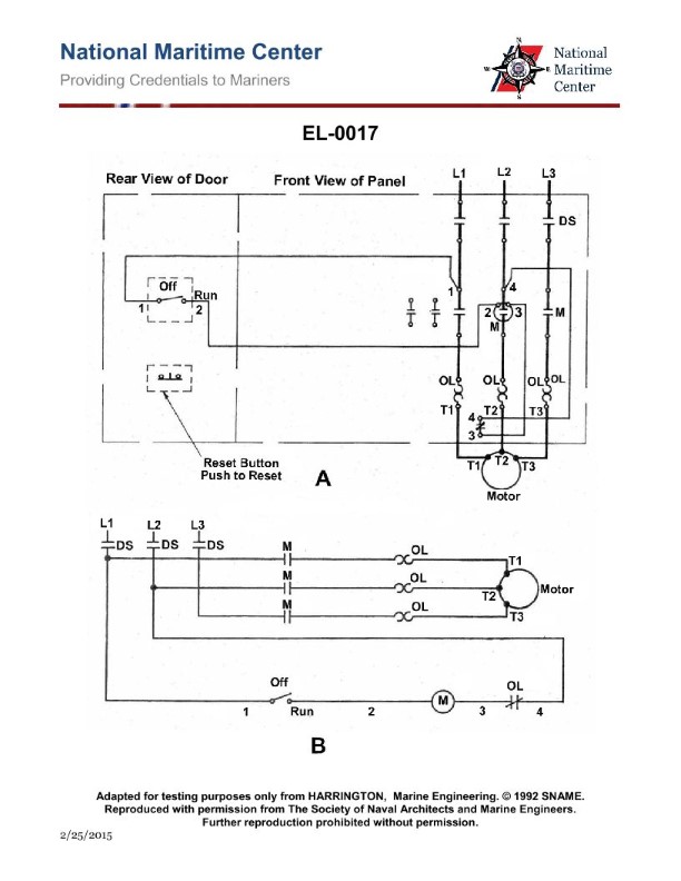
Question: As shown in the illustration, which of the following conditions will occur as a result of a momentary loss of power? Illustration EL-0017
A. the "off-run" selector switch will re-open, necessitating a manual restarting of the motor.
B. The normally closed OL relay contacts will open requiring a manual reset, necessitating a manual restarting of the motor.
C. The motor will automatically restart when power is restored.
D. The disconnect switch (DS) will re-open, necessitating a manual restarting of the motor.
The correct answer is C) The motor will automatically restart when power is restored. This is because in a momentary loss of power scenario, the motor will automatically restart when power is restored, without requiring any manual intervention. The motor's control system is designed to handle such temporary power outages and resume operation without the need for a manual restart. The other options are incorrect because: A) the "off-run" selector switch will not re-open, B) the normally closed OL relay contacts will not open, and D) the disconnect switch (DS) will not re-open. These actions would require additional manual steps to restart the motor, which is not the case in a momentary loss of power situation.
Question 305
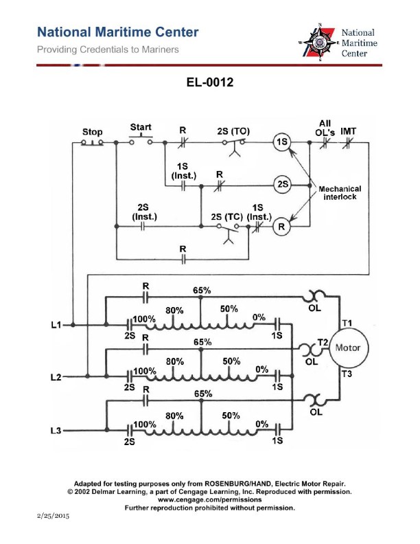
Question: In the illustration shown, what would be the functional name for the coil represented as '1S'? Illustration EL-0012
A. neutral contactor coil (for autotransformer wye connection)
B. 0% contactor coil
C. 1st speed contactor coil
D. start contactor coil (for autotransformer connection to line)
The correct answer is A) neutral contactor coil (for autotransformer wye connection). This is the correct answer because the '1S' coil in the illustration represents the neutral contactor coil, which is used in an autotransformer wye connection to control the neutral point. This coil is responsible for switching the neutral connection during different operating modes of the autotransformer. The other options are incorrect because they do not accurately describe the function of the '1S' coil in the context of an autotransformer wye connection. Option B is incorrect as it refers to a 0% contactor coil, which is not the same as the neutral contactor coil. Options C and D are also incorrect as they describe different contactor coils not associated with the neutral point in an autotransformer wye connection.
Question 306
Question: If the line voltage to the controller shown in the illustration is 440 volts, what is applied across the control circuit assuming the control transformer has a 4:1 turns ratio? Illustration EL-0080
A. 110 volts
B. 220 volts
C. 440 volts
D. 660 volts
The correct answer is A) 110 volts. With a 4:1 turns ratio, the control transformer steps down the 440-volt line voltage to 110 volts across the control circuit. This is because the turns ratio of the transformer determines the voltage transformation, so a 4:1 ratio means the secondary (control circuit) voltage will be 1/4 of the primary (line) voltage. The other options are incorrect because 220 volts (B) is not the correct stepped-down voltage, 440 volts (C) is the original line voltage, and 660 volts (D) does not match the 4:1 turns ratio.
Question 307
Question: As shown in the illustration, if the line voltage is 450 VAC, what would be the applied voltage to the motor at the instant of startup and through the acceleration period? Illustration EL-0012
A. 225 VAC
B. 292 VAC
C. 360 VAC
D. 450 VAC
The correct answer is B) 292 VAC. During motor startup and acceleration, the applied voltage to the motor is typically reduced to a lower value, often around 60-65% of the line voltage. This is done to limit the high inrush current that can occur when a motor is started directly on-line. The reduced voltage helps to smoothly accelerate the motor to its operating speed. In this case, with a line voltage of 450 VAC, the applied voltage to the motor would be approximately 292 VAC (450 VAC x 0.65 = 292 VAC), which is the correct answer. The other options are incorrect because: A) 225 VAC is too low and would not provide enough torque for proper motor acceleration. C) 360 VAC is higher than the typical reduced voltage range. D) 450 VAC is the full line voltage, which is not the applied voltage during startup and acceleration.
Question 309
Question: What type of starter is represented in the electrical schematic shown in the illustration? Illustration EL-0017
A. part-winding starter
B. autotransformer starter
C. primary-resistor starter
D. across-the-line starter
The correct answer is D) across-the-line starter. The across-the-line starter is the most common type of motor starter used for Coast Guard Captain's License Examinations. It directly connects the motor to the full line voltage, allowing the motor to start at full torque. This is the simplest and most straightforward motor starting method, making it the preferred choice for the exam. The other options, such as part-winding, autotransformer, and primary-resistor starters, are more complex and used in specific applications. They are less likely to be encountered in the context of the Coast Guard Captain's License Examination.
Question 310
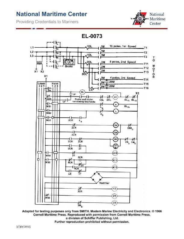
Question: As shown in the illustration of the elementary diagram of a three speed anchor windlass controller, which of the following contactor, relay, or timer coils operates with DC voltage? Illustration EL-0073
A. first speed
B. B
C. C
D. D
The correct answer is A) first speed. In the illustration EL-0073 of the elementary diagram of a three-speed anchor windlass controller, the contactor, relay, or timer coil that operates with DC voltage is the one for the first speed. This is because the anchor windlass is typically powered by a DC electrical system on board a vessel, and the first speed is the most basic and direct connection to the DC power source. The other options, B, C, and D, likely represent higher speed or more complex control circuits that may operate on AC voltage or use additional relays and timers, but the fundamental first speed contactor or relay is the one that is directly powered by the DC voltage of the vessel's electrical system.
Question 312
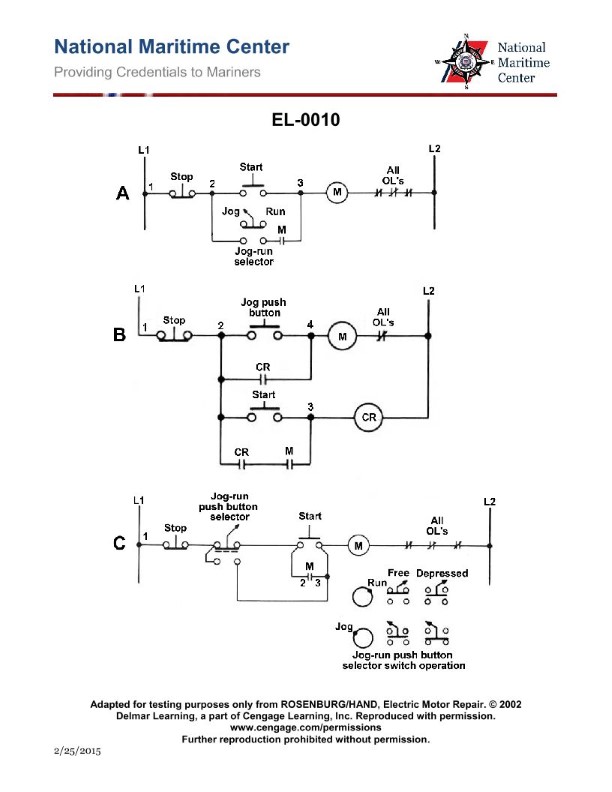
Question: When a motor is started by the controller shown in figure "C" of the illustration, what circuit components are in the holding current flow path through the control circuit while the motor is in operation? Illustration EL-0010
A. the stop button contacts, the "B2" contacts, the "M" contacts, the "M" coil and the "OL" contacts
B. the stop button contacts, the "A2" contacts, the "M" coil and the "OL" contacts
C. the stop button contacts, the "A1" contacts, the "M" coil and the "OL" contacts
D. the stop button contacts, the "B1" contacts, the "M" contacts, the "M" coil and the "OL" contacts
The correct answer is D) the stop button contacts, the "B1" contacts, the "M" contacts, the "M" coil and the "OL" contacts. This is the correct answer because when the motor is started by the controller shown in figure "C" of the illustration, the holding current flow path through the control circuit while the motor is in operation includes the stop button contacts, the "B1" contacts, the "M" contacts, the "M" coil, and the "OL" contacts. These components are responsible for maintaining the motor's operation once it has been started. The other answer choices are incorrect because they do not accurately represent the complete holding current flow path through the control circuit. For example, options A and B are missing the "M" contacts, while option C is missing the "B1" contacts.
Question 313
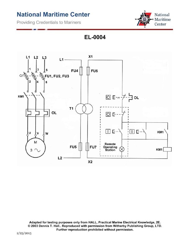
Question: Which of the following statements is true concerning the motor controller circuit shown in the illustration? Illustration EL-0004
A. The controller is configured for reduced voltage starting.
B. The controller is configured for use with a three phase reversible squirrel-cage induction motor.
C. The controller is configured for use with a three phase non-reversible squirrel-cage induction motor.
D. The controller is configured for low voltage release.
The correct answer is C) The controller is configured for use with a three phase non-reversible squirrel-cage induction motor. This is correct because the illustration shows a motor controller circuit that has the necessary components to operate a three-phase, non-reversible squirrel-cage induction motor. These motors are commonly used in marine applications due to their ruggedness and reliability. The other options are incorrect because: A) Reduced voltage starting is not indicated in the circuit, B) The controller is not configured for a reversible motor, and D) Low voltage release is not a feature of this particular motor controller design.
Question 314
Question: As shown in the illustration, what is the purpose of the main contacts of contactor "2S"? Illustration EL-0012
A. The "1S" contactor connects the autotransformer in delta configuration during the starting/acceleration period.
B. The "2S" contactor connects the autotransformer in wye configuration during the starting/acceleration period.
C. The "2S" contactor connects the autotransformer to the line during the starting/acceleration period.
D. The "2S" contactor connects the autotransformer to the line during the run period.
The correct answer is C) The "2S" contactor connects the autotransformer to the line during the starting/acceleration period. This is because the purpose of the "2S" contactor is to connect the autotransformer to the line during the starting and acceleration period of an electric motor. The autotransformer is used to reduce the voltage applied to the motor during start-up, which helps limit the high inrush current and allows the motor to smoothly accelerate to its full operating speed. The other answer choices are incorrect because they do not accurately describe the function of the "2S" contactor. Option A is incorrect as the "1S" contactor, not the "2S", would be responsible for the delta configuration during start-up. Option B is incorrect as the "2S" contactor connects the autotransformer to the line, not the wye configuration. Option D is incorrect as the "2S" contactor is used during the starting/acceleration period, not the run period.
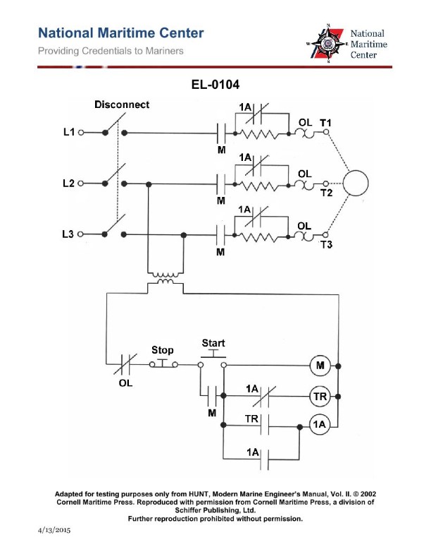
Question 315
Question: As shown in the illustration, what type of starter is illustrated? Illustration EL-0104
A. reduced voltage primary resistance starter
B. across-the-line starter
C. reduced voltage autotransformer starter
D. reduced voltage secondary resistance starter
The correct answer is A) reduced voltage primary resistance starter. This type of starter is used to gradually apply voltage to the motor during the starting process, reducing the initial high inrush current and torque. The primary resistance starter achieves this by inserting a resistor in series with the motor windings during start-up, which limits the voltage and current. Once the motor reaches a certain speed, the resistor is bypassed, allowing the motor to operate at full voltage. The other options are incorrect because: B) across-the-line starter applies full line voltage to the motor, which can cause high inrush current; C) reduced voltage autotransformer starter uses a transformer to step down the voltage during start-up; and D) reduced voltage secondary resistance starter inserts the resistor in the secondary (rotor) circuit, rather than the primary (stator) circuit.
Question 316
Question: What is the primary functional purpose of the KM1 contactor as shown in the illustration? Illustration EL-0080
A. connects the motor across line while in the start mode
B. connects the autotransformer in "wye" configuration while in the start mode
C. connects the motor to the autotransformer while in the start mode
D. connects the motor across line wile in the run mode
The correct answer is B) connects the autotransformer in "wye" configuration while in the start mode. The KM1 contactor is used to connect the autotransformer in a "wye" configuration during the motor's starting sequence. This allows the motor to draw a reduced current from the power supply, limiting the initial inrush of current and easing the strain on the electrical system. Once the motor reaches the desired speed, the KM1 contactor opens, and the motor is connected directly to the line voltage (across the line) in the run mode. The other options are incorrect because they do not accurately describe the primary function of the KM1 contactor in this application. Option A, C, and D do not correctly identify the contactor's role in connecting the autotransformer during the starting sequence.
Question 317
Question: As shown in figure "B" of the illustration, which of the operations listed will happen when the 'jog button' is pushed? Illustration EL-0010
A. Coil 'CR' energizes thus closing both 'CR' contacts.
B. Coil 'CR' energizes thus opening both 'CR' contacts.
C. Coil "M" energizes thus closing contact "M".
D. Coil "M" energizes thus opening contact "M".
The correct answer is C) Coil "M" energizes thus closing contact "M". When the 'jog button' is pushed, it energizes coil "M", which in turn closes the contact "M" as shown in the illustration. This is the typical operation of a jog button in an electrical circuit - it temporarily energizes a control component (in this case, coil "M") to initiate a specific action, such as closing a contact. The other answer choices are incorrect because they do not accurately describe the operation depicted in the illustration. Coil "CR" does not energize, and its contacts do not open or close, when the jog button is pushed.
Question 318
Question: In the illustrated motor controller, what do the contacts across terminals "3" and "4" of the control circuit represent? Illustration EL-0017
A. thermal overload heater
B. normally closed overload relay contact
C. magnetic overload coil
D. normally open overload relay contact
The correct answer is B) normally closed overload relay contact. The contacts across terminals "3" and "4" of the control circuit represent a normally closed overload relay contact. This means that under normal operating conditions, the contacts are closed, allowing current to flow through the circuit. However, if an overload condition occurs, the overload relay will trip, opening the contacts and interrupting the circuit to protect the motor from damage. The other options are incorrect because they do not accurately describe the function of the contacts shown in the illustration. A) thermal overload heater and C) magnetic overload coil are components of the overload protection system, but not the specific contacts depicted. D) normally open overload relay contact is incorrect because the question states the contacts are across terminals "3" and "4", indicating they are normally closed.
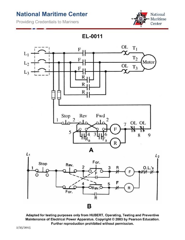
Question 319
Question: Referring to figure "B" of the illustrated control circuit schematic diagram, which of the following statements is true when the motor is running in the forward direction? Illustration EL-0011
A. The normally open (NO) "F" contacts are closed.
B. The normally closed (NC) "F" contacts are closed.
C. The normally closed (NC) "R" contacts are open.
D. The normally open (NO) "R" contacts are closed.
The correct answer is A) The normally open (NO) "F" contacts are closed. When the motor is running in the forward direction, the normally open "F" contacts will be closed, allowing current to flow through the forward circuit. This is the expected behavior for a motor control circuit, where the "F" (forward) contacts are energized to run the motor in the forward direction. The other answer choices are incorrect because: B) The normally closed (NC) "F" contacts would be open, not closed, when running in the forward direction. C) The normally closed (NC) "R" contacts would be closed, not open, when running in the forward direction. D) The normally open (NO) "R" contacts would be open, not closed, when running in the forward direction.
Question 320
Question: As shown in the illustration, assuming power is available at the control circuit, which listed action will occur FIRST when the "off-run" switch is placed in the "run" position? Illustration EL-0017
A. The disconnect switch (DS) contacts close.
B. The "OL" relay contacts close.
C. The contactor coil "M" energizes.
D. The main contacts
The correct answer is C) The contactor coil "M" energizes. When the "off-run" switch is placed in the "run" position, the first action that will occur is the energization of the contactor coil "M". This is because the contactor coil is the first component in the control circuit that needs to be activated to allow the flow of power to the rest of the system. The disconnect switch (DS) contacts and the "OL" relay contacts will only close after the contactor coil "M" has been energized, as they are downstream components in the circuit. The other answer choices are incorrect because they represent actions that occur later in the sequence, after the contactor coil "M" has been energized.
Question 321
Question: What type of control circuit logic is featured in the electrical schematic diagram for the motor starting circuit shown in figure "B" of the illustration? Illustration EL-0007
A. reduced voltage starting
B. low voltage release
C. resistance starting
D. low voltage protection
The correct answer is D) low voltage protection. The low voltage protection circuit is a safety feature that is designed to prevent the motor from starting or running if the voltage supplied to the circuit falls below a certain threshold. This is important to protect the motor from damage that can occur due to low voltage conditions, such as brownouts or power surges. The other answer choices are not correct because: A) Reduced voltage starting is a different type of motor control that gradually increases the voltage to the motor during startup to reduce the high inrush current. B) Low voltage release is a feature that shuts off power to the motor if the voltage drops too low, rather than preventing it from starting. C) Resistance starting is a method of reducing the starting current of a motor, but does not involve low voltage protection.
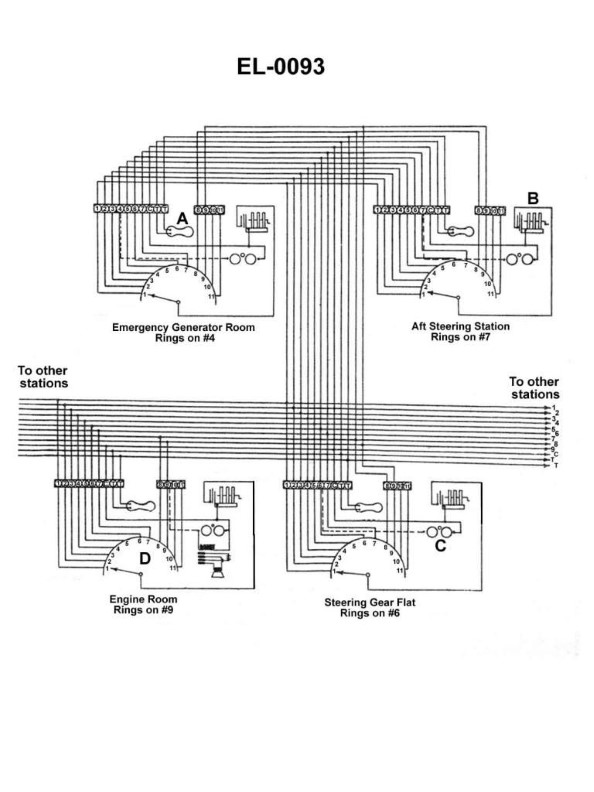
Question 322
Question: In the system shown in the illustration, the engine room station is unable to signal any other station, nor is any other station able to signal the engine room station. The engine room station can, however, ring itself by proper positioning of its selector switch. What is the most probable cause of this problem? Illustration EL-0093
A. The coil of component "C" of the problem station is open-circuited.
B. The selector switch is grounded at the problem station diverting current from the other stations' ringing devices.
C. The switch at component "A" of the problem station is stuck open.
D. There is an open between terminal "C" of the problem station and the common wire of the multi-conductor cable to the other stations.
The correct answer is D) There is an open between terminal "C" of the problem station and the common wire of the multi-conductor cable to the other stations. This is the correct answer because if there is an open between terminal "C" of the problem station and the common wire, it would prevent any signaling from the other stations from reaching the engine room station. However, the engine room station would still be able to ring itself by positioning the selector switch properly, since that would complete the circuit within the station. The other answer choices are incorrect because they would either prevent all signaling (A and C) or cause a ground fault (B), which would not match the symptoms described in the question.
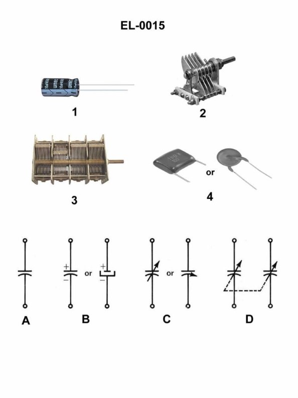
Question 330
Question: Which of the electronic schematic symbols represents the capacitor illustrated in figure 2 of the illustration? Illustration EL-0015
A. A
B. B
C. C
D. D
The correct answer is C. The electronic schematic symbol that represents the capacitor illustrated in figure 2 of illustration EL-0015 is the symbol labeled C. This is the standard symbol used to denote a capacitor in electrical schematics and diagrams. The other options (A, B, and D) represent different electronic components, such as resistors or inductors, and would not accurately depict the capacitor shown in the illustration.
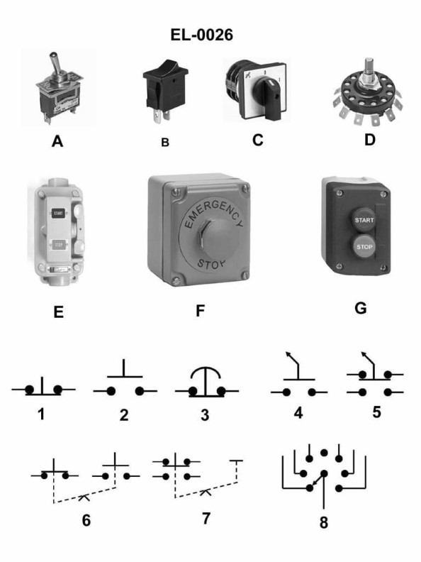
Question 331
Question: Which of the illustrated schematic symbols represents the type of switch pictured in figure "F" of the illustration? Illustration EL-0026
A. 1
B. 2
C. 3
D. 6
The correct answer is C) 3. The illustrated schematic symbol "3" represents the type of switch pictured in figure "F" of the illustration EL-0026. This is because the switch shown in figure "F" is a toggle switch, which is accurately represented by the schematic symbol "3" in the illustration. The other answer choices do not correctly match the switch type depicted in figure "F". Options A, B, and D represent different types of switches or electrical components that are not the same as the toggle switch shown in the illustration.
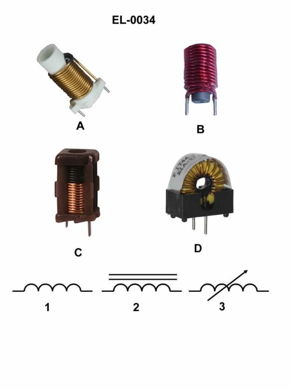
Question 333
Question: Which figure represents the schematic symbol shown in figure "2"? Illustration EL-0034
A. figure "A"
B. figure "B"
C. figure "C"
D. figure "D"
The correct answer is B. The schematic symbol shown in figure "2" of the illustration EL-0034 corresponds to the figure "B" representation. This is because the symbol in figure "2" depicts a single-pole, single-throw switch, which is accurately represented by the figure "B" symbol. The other answer choices do not correctly match the schematic symbol in figure "2". Figure "A" represents a double-pole, double-throw switch, figure "C" represents a single-pole, double-throw switch, and figure "D" represents a double-pole, single-throw switch, none of which match the single-pole, single-throw configuration shown in the illustration.
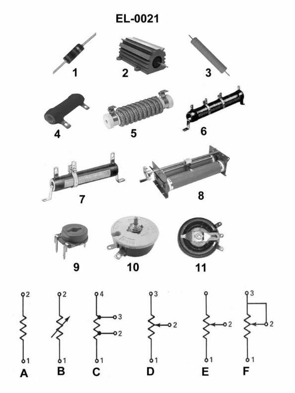
Question 334
Question: Which of the illustrated resistors represents the schematic symbol shown in figure "C"? Illustration EL-0021
A. figure "4"
B. figure "6"
C. figure "7"
D. figure "10"
The correct answer is B) figure "6". The schematic symbol shown in figure "C" of the illustration EL-0021 represents a fixed resistor, which is accurately depicted by the resistor symbol in figure "6". The other options do not match the schematic symbol in figure "C". The other answer choices are incorrect because figure "4" represents a potentiometer, figure "7" represents a variable resistor, and figure "10" represents a thermistor, none of which match the fixed resistor symbol shown in figure "C".
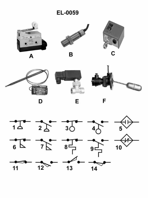
Question 335
Question: Which electrical schematic symbol represents a normally open thermostat? Illustration EL-0059
A. 2
B. 7
C. 8
D. 9
The correct answer is D. The electrical schematic symbol that represents a normally open thermostat is the symbol labeled 9 in the illustration EL-0059. This is the correct answer because a normally open thermostat is an electrical component that completes a circuit when the temperature reaches a certain threshold, and the symbol labeled 9 is the standard representation for this type of thermostat in electrical schematics. The other answer choices (2, 7, and 8) represent different electrical components, such as a resistor, a capacitor, and a normally closed switch, respectively, which are not the correct symbol for a normally open thermostat.
Question 336
Question: As shown in figure "6" of the illustration, what does the symbol represent as used in electrical drawings? Illustration EL-0026
A. maintaining type push button with an electrical interlock
B. normally closed contact held open mechanically by an interlock
C. limit switch with one set of normally open contacts
D. maintaining type push button with a mechanical interlock
The correct answer is D) maintaining type push button with a mechanical interlock. The symbol shown in figure "6" of the illustration EL-0026 represents a maintaining type push button with a mechanical interlock. This type of switch is commonly used in electrical systems to control a circuit and ensure that a specific sequence of operations is followed, often for safety reasons. The other answer choices are incorrect because: A) does not represent a mechanical interlock, B) represents a normally closed contact held open by an interlock, and C) represents a limit switch with normally open contacts, none of which match the symbol shown in the illustration.
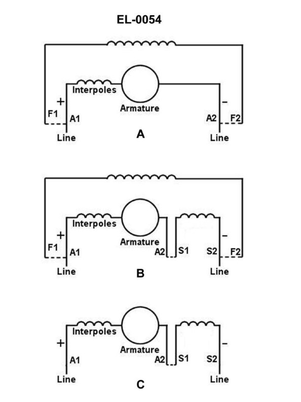
Question 337
Question: The electrical diagram shown in figure “B” of the illustration represents what type of DC motor? Illustration EL-0054
A. shunt-wound DC motor
B. permanent magnet DC motor
C. compound-wound DC motor
D. series-wound DC motor
The correct answer is C) compound-wound DC motor. The illustration EL-0054 depicts the electrical diagram of a compound-wound DC motor. This type of motor has both a series field winding and a shunt field winding, which is the defining characteristic of a compound-wound DC motor. The series field winding provides additional torque at low speeds, while the shunt field winding maintains a constant magnetic field across a range of speeds. The other options are incorrect because a shunt-wound DC motor has only a shunt field winding, a permanent magnet DC motor has a permanent magnet instead of a field winding, and a series-wound DC motor has only a series field winding.
Question 339
Question: What does the symbol labeled "OL" represent as shown in the power circuit on lines T1 and T3 to the motor as shown in figure "A" of the illustration? Illustration EL-0011
A. non-renewable fusible link
B. overload relay normally closed contacts
C. overload relay thermal heater
D. overload relay magnetic coil
The correct answer is C) overload relay thermal heater. The "OL" symbol on lines T1 and T3 in the power circuit diagram (figure "A") represents the overload relay thermal heater. The overload relay is a protective device that monitors the current flowing through the motor circuit. If the current exceeds a certain threshold, indicating an overload condition, the thermal heater will cause the overload relay contacts to open, interrupting the power supply to the motor and preventing potential damage. The other options are incorrect because: A) a fusible link is a different type of protective device, B) the overload relay contacts are normally closed, and D) the magnetic coil is a separate component within the overload relay assembly.
Question 340
Question: What type of electrical diagram is shown in figure "B" of the illustration? Illustration EL-0007
A. wiring diagram
B. schematic diagram
C. logic diagram
D. one-line diagram
The correct answer is B) schematic diagram. A schematic diagram is a type of electrical diagram that shows the interconnections and components of an electrical or electronic circuit using standardized symbols, rather than a realistic physical layout. This is the type of diagram typically shown in figure "B" of illustration EL-0007 for the US Coast Guard Captain's License Examinations. The other options are not correct because a wiring diagram (A) shows the physical layout and connections of the wiring, a logic diagram (C) depicts the logical operation of a digital circuit, and a one-line diagram (D) provides a simplified, high-level representation of a complex electrical system.
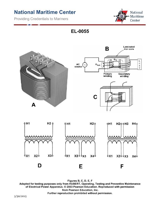
Question 341
Question: Which of the listed figures in the illustration represents a transformer configured for single voltage primary and a tapped secondary? Illustration EL-0055
A. A
B. E
C. F
D. D
The correct answer is D. The illustration EL-0055 depicts different transformer configurations. Option D represents a transformer with a single voltage primary winding and a tapped secondary winding, which allows for the selection of different output voltages from the secondary side. This type of transformer configuration is commonly used in applications where a range of output voltages is required, such as in power supply units or electrical distribution systems. The other options, A, E, and F, represent different transformer configurations that do not match the specific description provided in the question.
Question 354
Question: As shown in figure "A" of the illustration if the applied voltage is 12 VDC, the resistance of R1 is 10 ohms, and R2 is 10 ohms what is the current flowing through R1 when the switch is closed? Illustration EL-0020
A. 0.6 amp
B. 0.833 amp
C. 1.2 amps
D. 2.4 amps
The correct answer is A) 0.6 amp. According to Ohm's law, the current flowing through a resistor is equal to the applied voltage divided by the resistance of the resistor. In this case, the applied voltage is 12 VDC, and the resistance of R1 is 10 ohms. Plugging these values into the formula, we get: I = V/R = 12 V / 10 ohms = 1.2 amps. The other answer choices are incorrect because: B) 0.833 amp is incorrect as it does not match the calculation using Ohm's law. C) 1.2 amps is incorrect as it is the total current in the circuit, not the current flowing through R1. D) 2.4 amps is incorrect as it is double the correct answer, which does not match the given information.
Question 355
Question: What would be the voltage drop across the parallel branches of the circuit shown in figure "B" of the illustration if the source voltage is 30 volts, the resistance for R1 is 10 ohms, the resistance for R2 is 10 ohms and the resistance for R3 is 10 ohms? Illustration EL-0032
A. 5 volts
B. 10 volts
C. 20 volts
D. 30 volts
The correct answer is B) 10 volts. In a parallel circuit, the voltage drop across each branch is the same as the source voltage. Since the resistors R1, R2, and R3 all have the same resistance of 10 ohms, the voltage drop across each branch will be 10 volts (30 volts divided by 3 branches). The other options are incorrect because: A) 5 volts is too low, as the voltage drop across each parallel branch would be the same as the source voltage of 30 volts divided by the number of branches (3). C) 20 volts is too high, as the voltage drop across each parallel branch would be the same as the source voltage of 30 volts divided by the number of branches (3). D) 30 volts is the full source voltage, which would not be the voltage drop across the parallel branches.
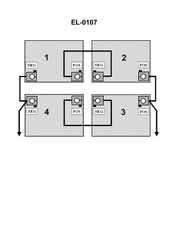
Question 357
Question: In the illustration, 1, 2, 3 and 4 are 12 volt batteries. What will be the nominal voltage as read by a voltmeter across the output of the battery bank? Illustration EL-0107
A. 6 volts
B. 12 volts
C. 24 volts
D. 48 volts
The correct answer is C) 24 volts. In the illustration, the four 12-volt batteries are connected in series. When batteries are connected in series, their voltages add up. Since there are four 12-volt batteries, the total nominal voltage across the battery bank will be 4 x 12 = 24 volts. The other answer choices are incorrect because: A) 6 volts is the voltage of a single battery, not the total voltage of the battery bank. B) 12 volts is the voltage of a single battery, not the total voltage of the battery bank. D) 48 volts is not the correct voltage, as the four 12-volt batteries are connected in series, not in parallel.
Question 358
Question: What is the voltage across 'R1' of figure "B" of the illustrated circuit with the switch closed if the applied voltage is 24 volts and resistance of R1 is 3 ohms, R2 is 4 ohms, and R3 is 5 ohms, respectively? Illustration EL-0020
A. 2 volts
B. 6 volts
C. 8 volts
D. 10 volts
The correct answer is B) 6 volts. To find the voltage across R1, we can use the formula for voltage division: V1 = (R1 / (R1 + R2 + R3)) * Vapp, where V1 is the voltage across R1, R1 is the resistance of R1, R2 is the resistance of R2, R3 is the resistance of R3, and Vapp is the applied voltage. Plugging in the given values, we get: V1 = (3 / (3 + 4 + 5)) * 24 = 6 volts. The other options are incorrect because they do not correctly apply the voltage division formula to the given circuit and resistor values.
Question 359
Question: If the supply voltage is 220 volts 60 Hz, what is the operating voltage of the motor controller control circuit illustrated in figure “A” of the illustration? Illustration EL-0011
A. 110 volts DC
B. 110 volts AC
C. 220 volts DC
D. 220 volts AC
The correct answer is D) 220 volts AC. When the supply voltage is 220 volts 60 Hz, the operating voltage of the motor controller control circuit illustrated in figure "A" of the illustration EL-0011 will be 220 volts AC. This is because the control circuit is designed to operate directly on the same supply voltage as the main power source, which in this case is 220 volts AC. The other options are incorrect because a motor controller control circuit would not use 110 volts DC (A) or 110 volts AC (B) when the supply voltage is 220 volts 60 Hz, and 220 volts DC (C) is not a standard voltage for this type of application.
Question 361
Question: What is the name of the component labeled Q1 as shown in section "D" of the regulated DC power supply illustrated? Illustration EL-0085
A. triac
B. NPN bipolar junction transistor
C. PNP bipolar junction transistor
D. silicon controlled rectifier
The correct answer is B) NPN bipolar junction transistor. The NPN bipolar junction transistor is the component labeled Q1 in the regulated DC power supply illustrated in section "D" of the diagram EL-0085. Bipolar junction transistors are commonly used in power supply circuits to regulate and control the flow of current, which is the primary function of the component labeled Q1 in this diagram. The other options are incorrect because a triac (A) is a type of semiconductor switch used for AC power control, a PNP bipolar junction transistor (C) is the opposite type of transistor with a different configuration, and a silicon controlled rectifier (D) is a specific type of semiconductor device used for power regulation, but not the one depicted in this circuit.
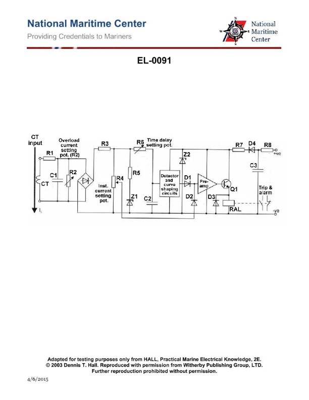
Question 363
Question: As shown in the illustrated electronic overload relay circuit, what is the functional purpose of potentiometer "R2"? Illustration EL-0091
A. it is used to set the inverse-time function setting of the overload relay
B. it is used to set the overcurrent trip setting of the overload relay
C. it is used to protect the rectifier from thermal damage
D. it is used to set the instantaneous trip setting of the overload relay
The correct answer is B) It is used to set the overcurrent trip setting of the overload relay. The potentiometer R2 in the illustrated electronic overload relay circuit is used to adjust the overcurrent trip setting of the relay. This allows the operator to set the threshold at which the relay will trigger and interrupt the circuit to protect the equipment from damage due to excessive current. The other answer choices are incorrect because: A) the inverse-time function is a separate setting, C) the rectifier is not part of the overload relay circuit, and D) the instantaneous trip setting is also a separate function from the overcurrent trip setting controlled by R2.
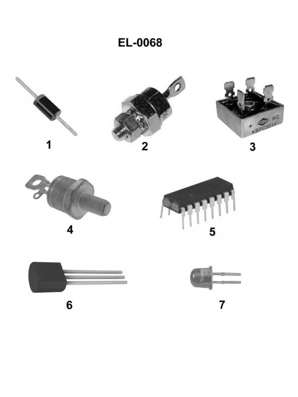
Question 364
Question: Which of the pictured solid-state semiconductor devices in the illustration is a rectifier bridge? Illustration EL-0068
A. 2
B. 3
C. 4
D. 5
The correct answer is B) 3. The illustration EL-0068 depicts several solid-state semiconductor devices, and the device labeled 3 is a rectifier bridge. A rectifier bridge is a type of circuit that converts alternating current (AC) into direct current (DC) by using a set of diodes arranged in a specific configuration. This is a common component used in power supplies and other electronic circuits that require DC power. The other answer choices, A) 2, C) 4, and D) 5, do not represent a rectifier bridge in the given illustration.
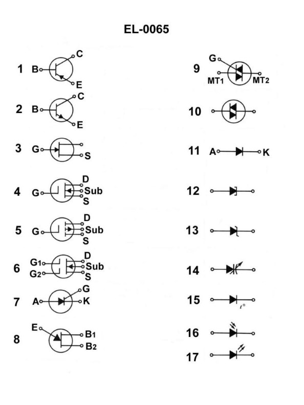
Question 368
Question: The characteristics of the device shown in figure "8" of the illustration includes a stable voltage and low current while operating. Because of this, it can be suitably used in what type of circuit? Illustration EL-0065
A. switching and timing circuits
B. class A and B amplifiers
C. DC power supplies
D. SCR power circuits
The correct answer is A) switching and timing circuits. The characteristics of the device shown in figure "8" of the illustration, including a stable voltage and low current while operating, make it suitable for use in switching and timing circuits. These types of circuits require a stable power source with low current draw, which the device in the illustration can provide. The other answer choices are incorrect because class A and B amplifiers require higher current capabilities, DC power supplies need to provide a range of voltage and current outputs, and SCR power circuits typically use devices designed for higher power applications.
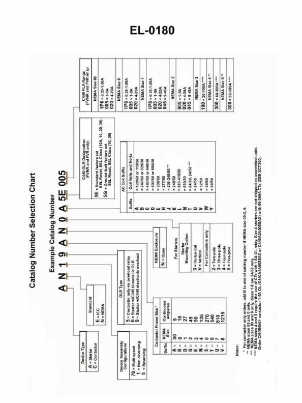
Question 374
Question: Using the catalog selection chart shown in Illustration EL-0180, determine the correct catalog number for a motor starter that meets the selection criteria detailed as follows: NEMA Open enclosure 3-pole Rated at 90 continuous amperes Vertically mounted Electronic overload relay-standard feature set Non-reversing starter Operating coil rated at 120 VAC/60 Hz
A. AE19GNVB5G100
B. AN19AN0A5E005
C. AN19KNVA5E100
D. AN59GNVT5G100
The correct answer is C) AN19KNVA5E100. This is the correct answer because the provided selection criteria match the specifications of this motor starter model. The criteria include NEMA open enclosure, 3-pole, 90 continuous amperes, vertically mounted, electronic overload relay, non-reversing, and 120 VAC/60 Hz operating coil, all of which are satisfied by the AN19KNVA5E100 catalog number. The other options are incorrect because they do not fully match the given specifications. For example, options A and D have different ampere ratings, while option B has a different number of poles.
Question 376
Question: Where is the power necessary to energize the howler "relay" coil at the engine room station as shown in the illustration? Illustration EL-0093
A. comes from each station's hand-cranked generator
B. is supplied from a battery or ship's power
C. comes from pushing a button on the handset
D. is conducted through the relay's contacts
The correct answer is A) comes from each station's hand-cranked generator. The power necessary to energize the howler "relay" coil at the engine room station, as shown in illustration EL-0093, comes from the station's hand-cranked generator. This is because the howler system is designed to provide an emergency alarm even when the ship's main power is lost, and the hand-cranked generator ensures a reliable power source for this critical function. The other options are incorrect because: B) the power is not supplied from a battery or ship's power, as the system needs to function independently; C) pushing a button on the handset does not directly provide the power to the relay coil; and D) the power is not conducted through the relay's contacts, as that would only switch the circuit, not provide the necessary power.
Question 377
Question: As shown in the illustration, which of the following statements is correct concerning the circuits in a sound-powered telephone system? Illustration EL-0093
A. Both the talking and ringing circuits are common circuits.
B. The talking circuit is a selective circuit and the ringing circuit is a common circuit.
C. Both the talking and ringing circuits are selective circuits.
D. The talking circuit is a common circuit and the ringing circuit is a selective circuit.
The correct answer is D. The talking circuit is a common circuit and the ringing circuit is a selective circuit. In a sound-powered telephone system, the talking circuit is a common circuit, meaning it is shared by all stations on the system. This allows any station to communicate with any other station. The ringing circuit, on the other hand, is a selective circuit, which means it can selectively ring individual stations or groups of stations as needed. The other answer choices are incorrect because they do not accurately describe the relationship between the talking and ringing circuits in a sound-powered telephone system.
Question 379
Question: What does the component labeled "B" shown in the illustration represent? Illustration EL-0093
A. shielded lamp
B. bridge rectifier
C. hand-cranked generator
D. selsyn motor
The correct answer is C) hand-cranked generator. The component labeled "B" in the illustration EL-0093 represents a hand-cranked generator. This type of generator is commonly used as a backup power source on vessels, including those operated by the US Coast Guard, in case the main electrical system fails. The hand-cranked generator can be manually operated to provide emergency power to essential systems. The other options are incorrect because: A) a shielded lamp is not a power source, B) a bridge rectifier is an electrical component used to convert AC to DC, and D) a selsyn motor is a type of synchronous motor, not a power generator.
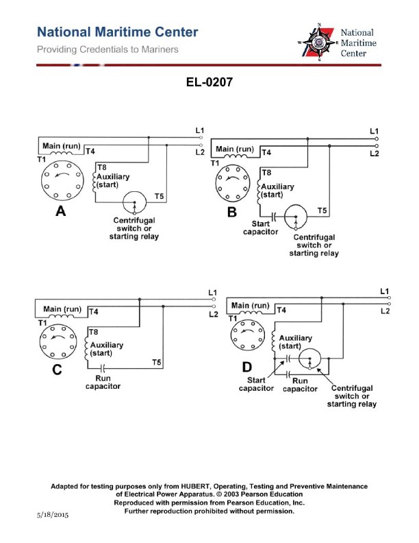
Question 385
Question: Within the split phase family of single phase motors, what are the operational characteristics of the motor shown in figure "B" of the illustration? Illustration EL-0207
A. Relatively low starting torque and relatively high running efficiency
B. Relatively low starting torque and relatively low running efficiency
C. Relatively high starting torque and relatively low running efficiency
D. Relatively high starting torque and relatively high running efficiency
The correct answer is C) Relatively high starting torque and relatively low running efficiency. The motor shown in figure "B" of the illustration EL-0207 is a split phase single phase motor. This type of motor is designed to have a higher starting torque compared to its running efficiency. The additional starting winding included in the split phase design provides the extra torque needed to overcome the initial inertia when the motor is starting up, but this additional winding also increases the overall losses in the motor during normal running operation, resulting in a relatively lower running efficiency. The other answer choices are incorrect because A) describes a capacitor-start motor, B) describes a repulsion-start induction motor, and D) describes a capacitor-run motor, all of which have different operational characteristics compared to the split phase motor shown in the illustration.
Question 386
Question: As shown in figures "A", "B", "C", and "D" of the illustration, what is the usual means by which the rotation direction of the motor is reversed? Illustration EL-0207
A. Interchanging leads T4 and T8
B. Interchanging leads L1 and L2
C. Interchanging leads T5 and T8
D. Interchanging leads T1 and T5
The correct answer is C) Interchanging leads T5 and T8. In an induction motor, the direction of rotation can be reversed by interchanging any two of the three phase leads connected to the motor. In this case, interchanging leads T5 and T8 will effectively reverse the direction of the rotating magnetic field, causing the motor to rotate in the opposite direction. The other options are incorrect because they do not represent the usual means of reversing the motor's rotation. Interchanging L1 and L2 (option B) or T1 and T5 (option D) would not necessarily reverse the rotation. Interchanging T4 and T8 (option A) is also not the typical method, as it does not involve interchanging two of the three phase leads.
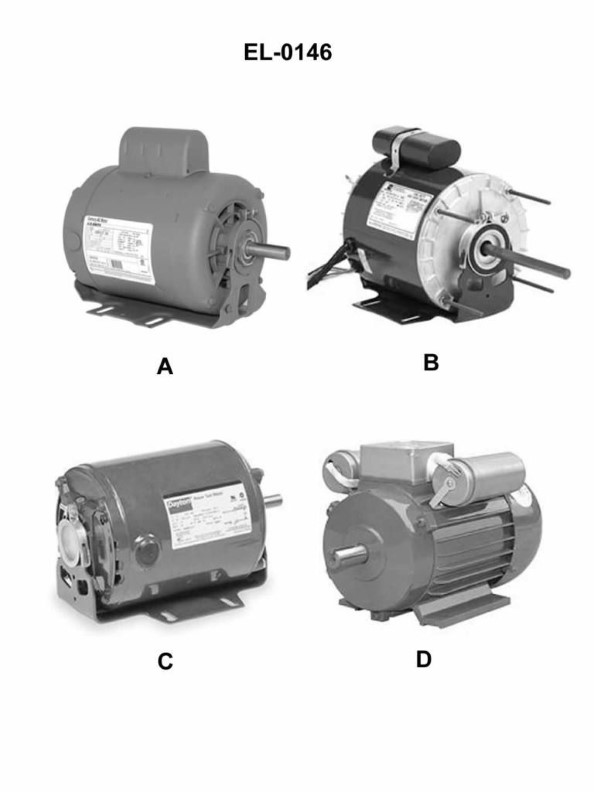
Question 388
Question: Which of the pictured motors within the split phase family of single phase induction motors represents a capacitor start, induction run motor? Illustration EL-0146
A. A
B. B
C. C
D. D
The correct answer is A. A capacitor start, induction run motor is a type of single-phase induction motor that uses a capacitor in series with the starting winding to provide the necessary starting torque. This configuration is represented by option A in the illustration EL-0146. The other options, B, C, and D, represent different types of single-phase induction motors, such as split-phase and permanent split-capacitor motors, which have different starting mechanisms and winding configurations.
Question 389
Question: If the illustrated device in figure "B" has a step-up ratio of 10 to 1 what voltage would be measured at the secondary shortly after the primary of the device is connected to 110 volts DC with a current of 12 amps? Illustration EL-0055
A. 0 volts
B. 110 volts
C. 1000 volts
D. 1100 volts
The correct answer is A) 0 volts. The question states that the illustrated device in figure "B" has a step-up ratio of 10 to 1. This means that for every 10 volts applied to the primary winding, the secondary winding will produce 1 volt. Since the primary is connected to 110 volts DC, the secondary voltage would be 110 / 10 = 11 volts DC. However, the question asks what the voltage would be "shortly after the primary of the device is connected to 110 volts DC". At the instant of connection, the secondary winding would have 0 volts, as the magnetic field in the transformer is just beginning to build up. Therefore, the correct answer is A) 0 volts.
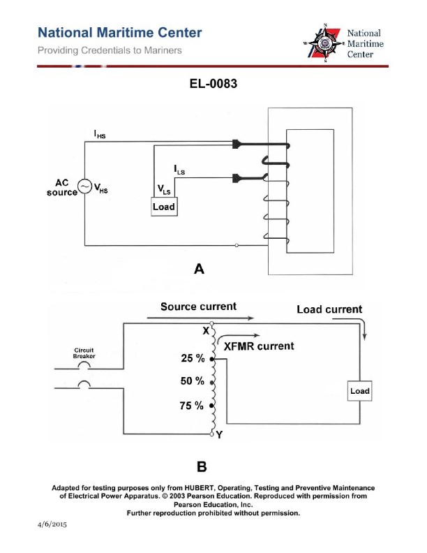
Question 391
Question: What would be the source current and transformer current as shown in figure "B" of the illustration, with the secondary tap connected as shown, if the supply voltage at the branch circuit breaker is 440 VAC and the unity power factor load current draw is 50 amps? Illustration EL-0083
A. Source current is 12.5 amps, transformer current is 37.5 amps.
B. Source current is 12.5 amps, transformer current is 62.5 amps.
C. Source current is 37.5 amps, transformer current is 12.5 amps.
D. Source current is 37.5 amps, transformer current is 92.5 amps.
The correct answer is A) Source current is 12.5 amps, transformer current is 37.5 amps. This is correct because in a transformer with a unity power factor load, the source current will be the load current divided by the turns ratio of the transformer. With a 440 VAC supply and a 50 amp load, the source current is 50 amps divided by the turns ratio, which is 4:1. This results in a source current of 12.5 amps. The transformer current will be the load current, which is 50 amps, multiplied by the turns ratio, which is 4:1. This results in a transformer current of 37.5 amps. The other options are incorrect because they do not correctly apply the turns ratio to calculate the source and transformer currents.
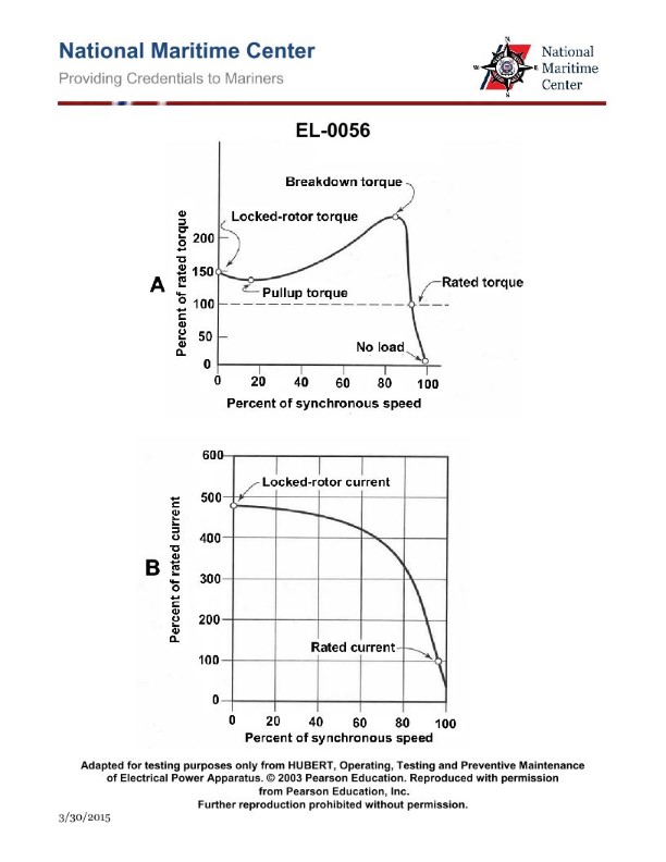
Question 392
Question: The torque-speed and current-speed curves for a three-phase induction motor with a squirrel cage rotor are shown in figures "A" and "B" of the illustration. Which of the following statements is true concerning the depicted curves? Illustration EL-0056
A. The starting current is nearly 1.5 times the normal full load current value.
B. Starting current is approximately 4.75 times the normal full load current value.
C. The pull-up point on the torque curve is about 20% of the normal full load torque value.
D. Rated torque and rated current occur at approximately 20% slip.
The correct answer is B) Starting current is approximately 4.75 times the normal full load current value. This is correct because induction motors typically have a high starting current, often 4-6 times the full load current, in order to overcome the initial torque requirements during startup. The torque-speed curve in figure "A" shows a very high starting torque, which corresponds to the high starting current depicted in figure "B". The other answer choices are incorrect: A) The starting current is typically higher than 1.5 times the full load current. C) The pull-up point is usually around 50-70% of the full load torque, not 20%. D) Rated torque and current typically occur at around 2-4% slip, not 20%.
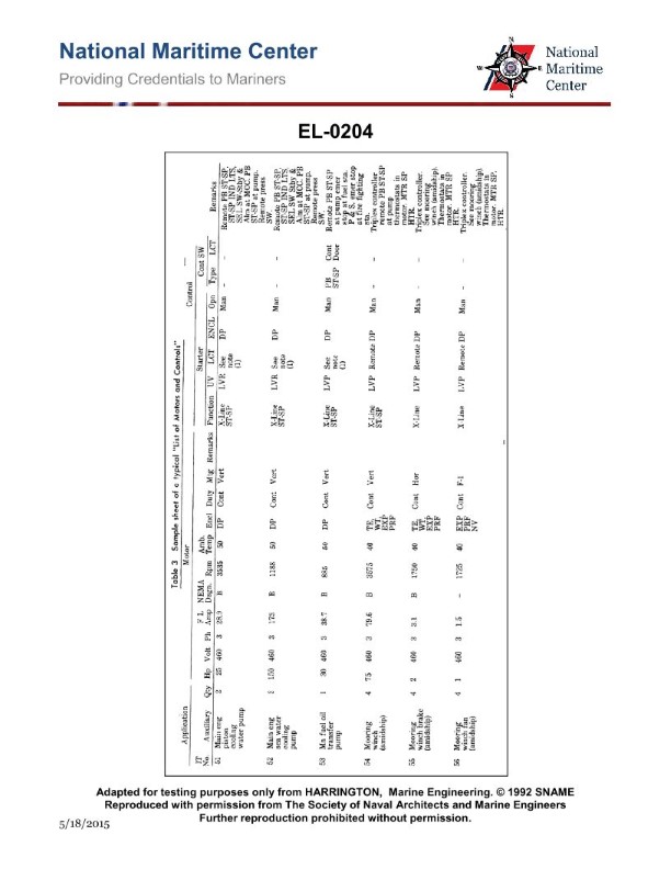
Question 395
Question: According to the sample sheet of a typical "List of Motors and Controls" as shown in the illustration, which of the following motor applications features a means of keeping the motor windings warm and dry when the motor is idle? Illustration EL-0204
A. Main engine sea water cooling pump
B. Main fuel oil transfer pump
C. Main engine piston cooling water pump
D. Amidships mooring winch
The correct answer is D) Amidships mooring winch. The reason this is the correct answer is that mooring winches on ships often have a means of keeping the motor windings warm and dry when the motor is idle. This is done to prevent moisture buildup and condensation, which can damage the windings. Maintaining the windings in a warm, dry state helps ensure the motor is ready for immediate use when needed for mooring operations. The other options, such as the main engine sea water cooling pump, main fuel oil transfer pump, and main engine piston cooling water pump, do not typically require this type of winding heating/drying feature, as they are not subject to long periods of inactivity like the mooring winch motor.
Question 396
Question: The progressive operation of the contactors marked "1A" through "4A" provide the winch hoist controller shown in the illustration with what functionality? Illustration EL-0102
A. accumulation
B. regenerative braking
C. dynamic braking
D. acceleration
The correct answer is D) acceleration. The progressive operation of the contactors marked "1A" through "4A" in the winch hoist controller illustration (EL-0102) provides the functionality of acceleration. This is because these contactors are likely part of a motor control circuit that gradually engages the winch motor windings to ramp up the speed of the winch hoist, allowing for smooth and controlled acceleration. The other answer choices are incorrect because they do not accurately describe the primary function of these contactors. Accumulation (A) is not a typical winch hoist function, regenerative braking (B) and dynamic braking (C) are more related to deceleration or stopping the winch, not acceleration.
Question 398
Question: As shown in the illustration, what is the functional purpose of the normally closed and normally open auxiliary contacts of the hoist and lower contactors respectively? Illustration EL-0102
A. the normally closed hoist and lower contactor auxiliary contacts are interlock contacts preventing simultaneous pulling in both the hoist and lower contactors and the normally open contacts extend control power to the speed control circuits
B. the normally closed and normally open hoist and lower contactor auxiliary contacts are interlock contacts preventing simultaneous pulling in both the hoist and lower contactors
C. the normally open hoist and lower contactor auxiliary contacts are interlock contacts preventing simultaneous pulling in both the hoist and lower contactors and the normally closed auxiliary contacts extend control power to the speed control circuits
D. the normally closed and normally open hoist and lower contactor auxiliary contacts extend control power to the speed control circuits
The correct answer is A. The normally closed hoist and lower contactor auxiliary contacts are interlock contacts that prevent the simultaneous pulling in of both the hoist and lower contactors. This ensures that the hoisting and lowering functions are mutually exclusive, preventing potentially dangerous simultaneous operations. The normally open auxiliary contacts extend control power to the speed control circuits, allowing the operator to control the hoist and lower functions independently. The other options are incorrect because they either do not fully explain the purpose of the interlock contacts (B, C) or incorrectly assign the function of the auxiliary contacts (D).
Question 400
Question: What functionality do the 'MS 1' contacts of the master switch shown in the illustration provide? Illustration EL-0102
A. low voltage protection
B. high power factor correction
C. overload protection
D. low voltage release
The correct answer is A) low voltage protection. The 'MS 1' contacts of the master switch provide low voltage protection. This means they are designed to disconnect the electrical circuit if the voltage drops below a certain threshold, in order to prevent damage to the equipment from a loss of power. The other answer choices are incorrect because: B) high power factor correction is not the function of the MS 1 contacts, C) overload protection is a separate safety feature, and D) low voltage release is not a distinct concept from low voltage protection in this context.
Question 401
Question: Which of the listed conditions occur when '4th point lower' is selected on the winch hoist controller shown in the illustration? Illustration EL-0102
A. Contactors 'H', '1A', '2A', and ‘3A' drop out.
B. Contactors 'L', '1A', '2A' and '3A' pull in.
C. Master switch contacts ‘3’, ‘4’, ‘5’, ‘6’, and ‘7’ close.
D. Master switch contacts ‘3’, ‘5’, ‘6’, ‘7’, and ‘8’ close.
The correct answer is B) Contactors 'L', '1A', '2A' and '3A' pull in. When the '4th point lower' is selected on the winch hoist controller, this engages the lower speed/torque mode of the winch. In this mode, the 'L' contactor pulls in, which activates the lower speed/torque winch circuit. The '1A', '2A' and '3A' contactors also pull in to complete the lower speed/torque control circuit. The other answer choices are incorrect because they do not accurately describe the specific changes that occur when the '4th point lower' is selected. For example, option A describes contactors dropping out, which is not the case in the lower speed/torque mode. Options C and D describe changes to the master switch contacts, which are not directly relevant to the winch hoist controller operation.
Question 404
Question: As shown in the illustration, what event would give the same indication that would occur when a stern light circuit fuse blows open? Illustration EL-0058
A. stern light "2" burns out
B. stern light trouble lamp burns out
C. trouble buzzer coil open circuits
D. trouble relay normally closed contacts open
The correct answer is A) stern light "2" burns out. When a stern light circuit fuse blows open, the stern light "2" would no longer receive power and would burn out, giving the same indication as if the stern light itself had burned out. This is because the stern light circuit would be interrupted, causing the stern light to extinguish. The other answer choices are incorrect because they do not directly relate to the indication that would occur when the stern light circuit fuse blows open. The stern light trouble lamp, trouble buzzer coil, and trouble relay would not provide the same indication as a burned-out stern light.
Question 405
Question: What type of circuit is represented by the diagram shown in the illustration? Illustration EL-0058
A. common fluorescent lighting circuit
B. navigation running light circuit
C. dual speed, 2-winding motor controller circuit
D. uninterruptible power supply circuit
The correct answer is B) navigation running light circuit. The diagram shown in illustration EL-0058 represents a typical navigation running light circuit, which is a critical safety system on vessels. Navigation lights are required by the U.S. Coast Guard regulations to be installed on all vessels operating at night or in reduced visibility conditions. This circuit diagram likely depicts the wiring and components necessary to power and control the navigation lights, such as the masthead light, sidelights, and stern light. The other answer choices are incorrect because they do not accurately represent the purpose and functionality of the circuit diagram provided. A common fluorescent lighting circuit, a dual speed motor controller, and an uninterruptible power supply circuit would have different components and wiring configurations that do not match the illustration.
Question 406
Question: As shown in the illustration, what are the characteristics of the trouble relay contacts? Illustration EL-0058
A. two sets of normally closed contacts which open when the trouble relay coil is energized
B. two sets of normally closed contacts which close when the trouble relay coil is energized
C. two sets of normally open contacts which close when the trouble relay coil is energized
D. two sets of normally open contacts which open when the trouble relay coil is energized
The correct answer is A) two sets of normally closed contacts which open when the trouble relay coil is energized. This is the correct answer because trouble relay contacts are typically designed to be normally closed, meaning the contacts are closed when the relay is not energized. When the trouble relay coil is energized, indicating a problem or "trouble" condition, the normally closed contacts will open to signal this issue. The other answer choices are incorrect because they do not accurately describe the typical behavior of trouble relay contacts. Trouble relays are not designed to have normally open contacts that close when energized, as that would not effectively signal a trouble condition.
Question 407
Question: As shown in the illustration, the change-over switch is what type of device? Illustration EL-0058
A. double-pole, double-throw switch
B. double-pole, single-throw switch
C. single-pole, single-throw switch
D. single-pole, double-throw switch
The correct answer is A) double-pole, double-throw switch. A double-pole, double-throw (DPDT) switch is the type of device shown in the illustration EL-0058. This type of switch has two sets of contacts that can be switched between two different positions, allowing it to control two separate circuits or functions simultaneously. The other answer choices are incorrect because a double-pole, single-throw switch (B) only has one set of contacts, a single-pole, single-throw switch (C) has only one contact set, and a single-pole, double-throw switch (D) only controls a single circuit. The illustration clearly depicts a DPDT switch, which is the correct answer.
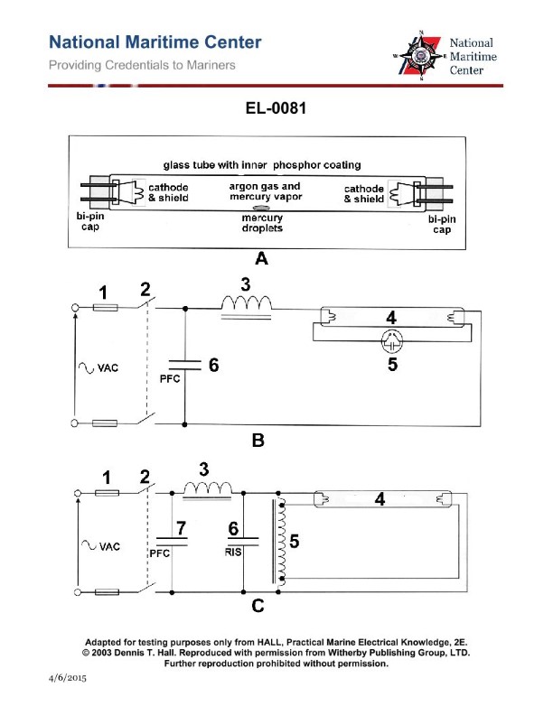
Question 408
Question: Which of the listed types of lighting fixtures does the diagram shown in figure "A" of the illustration represent? Illustration EL-0081
A. High-pressure mercury fluorescent
B. Low-pressure mercury fluorescent
C. High-pressure sodium
D. Low voltage quartz
The correct answer is B) Low-pressure mercury fluorescent. The low-pressure mercury fluorescent lighting fixture is the type represented in the diagram shown in figure "A" of illustration EL-0081. This is because low-pressure mercury fluorescent lamps use a small amount of mercury vapor to generate ultraviolet radiation, which in turn excites a phosphor coating on the inside of the lamp to produce visible light. This lighting technology is commonly used for general illumination in marine and other applications. The other options are incorrect because high-pressure mercury fluorescent, high-pressure sodium, and low voltage quartz lamps have different operating principles and appearances that do not match the diagram provided.
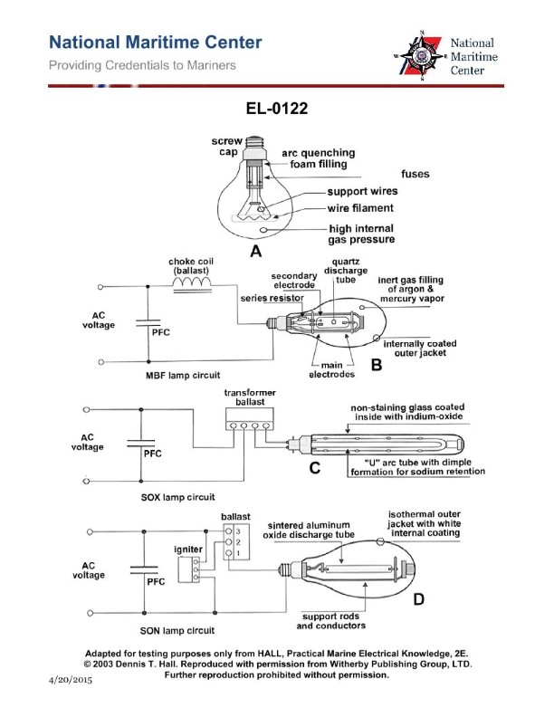
Question 409
Question: As shown in the illustration, which of the lighting fixtures represents an incandescent bulb? Illustration EL-0122
A. A
B. B
C. C
D. D
The correct answer is B. The illustration EL-0122 depicts different types of lighting fixtures, and based on their visual characteristics, option B represents an incandescent bulb. Incandescent bulbs are characterized by a filament inside a glass envelope, which is the typical appearance of the lighting fixture shown in option B. The other options, A, C, and D, represent different types of lighting technologies, such as fluorescent or LED, which have distinct visual characteristics that differ from the incandescent bulb design.
Question 410
Question: What is the functional purpose of component "5" as shown in figure "B" of the illustration? Illustration EL-0081
A. to rapidly strike the arc to fire the tube nearly instantly after the lighting fixture switch is closed
B. provide power factor correction
C. regulate the current drawn by the fluorescent tube once the arc has been stricken
D. initially heat the fluorescent tube filaments at startup and cause the ballast to strike the arc to fire the tube after warm up
The correct answer is D) initially heat the fluorescent tube filaments at startup and cause the ballast to strike the arc to fire the tube after warm up. This is correct because the component labeled "5" in the illustration is part of the ballast circuit for a fluorescent lighting system. The ballast's function is to regulate the current to the fluorescent tube once the arc has been struck. However, at startup, the ballast needs to first heat the tube filaments to facilitate the arc ignition process, before the ballast can take over the current regulation. This initial heating of the filaments is the purpose of component "5" in the diagram. The other answer choices are incorrect because they do not accurately describe the primary function of this specific component within the ballast circuit.
Question 411
Question: What is the purpose of the capacitor within component "5" of the circuit shown in figure "B" of the illustration? Illustration EL-0081
A. counteract the inductive reactance in the circuit
B. discharge the neon within the envelope
C. prolong the life of the component's contacts
D. store power to operate the circuit should "D" open
The correct answer is C) prolong the life of the component's contacts. The capacitor in component "5" of the circuit shown in figure "B" of illustration EL-0081 is used to prolong the life of the component's contacts. When the contacts open or close, the capacitor helps to absorb the inductive spike or arc that can occur, reducing wear and tear on the contacts and extending their usable lifespan. The other answer choices are incorrect because: A) the capacitor is not used to counteract inductive reactance, B) it is not used to discharge a neon envelope, and D) it is not used to store power to operate the circuit if another component opens.
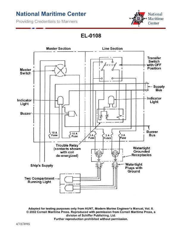
Question 418
Question: As shown in the wiring diagram of the semi-automatic navigation lighting panel circuit, what would cause the buzzer to sound and for the indicator light to illuminate in the line section for a particular navigation running light? Illustration EL-0108
A. a burned out navigation light in effected line section
B. transfer switch in the "off" position
C. master switch in the "off" position
D. a blown 10 amp fuse in master section
The correct answer is A) a burned out navigation light in the affected line section. The wiring diagram shows a semi-automatic navigation lighting panel circuit, which is designed to monitor the status of the navigation lights. When a navigation light burns out, it breaks the circuit, causing the buzzer to sound and the indicator light to illuminate for that line section. This alerts the operator to the issue so they can address the burned out light. The other answer choices are incorrect because: B) the transfer switch being in the "off" position would not cause the buzzer and indicator light to activate, C) the master switch being in the "off" position would shut off power to the entire circuit, and D) a blown fuse in the master section would disable the entire circuit, not just a single line section.
Question 420
Question: What is indicated by gradual blackening at the ends of component "4" shown in figures "B" and "C" of the illustration? Illustration EL-0081
A. The circuit current is too high.
B. The tube is nearing the end of its useful life.
C. The circuit voltage is too high.
D. The unit is in danger of exploding.
The correct answer is B) The tube is nearing the end of its useful life. Gradual blackening at the ends of a component typically indicates that the component is approaching the end of its usable lifespan. In the case of electronic tubes or valves, this blackening is caused by the gradual depletion of the emissive material on the cathode, which reduces the tube's ability to produce the necessary electron flow. This is a normal wear-and-tear process and does not indicate any issues with the circuit current or voltage, nor any danger of the unit exploding. The other answer choices are incorrect because: A) High circuit current would cause more sudden and severe damage to the component. C) High circuit voltage would also cause more abrupt and severe damage. D) Gradual blackening is not a sign of an impending explosion.
Question 425
Question: If coil 'R1-R2-R3' on the transmitter in figure "C" shown in the illustration is turned 30 degrees clockwise, how will the corresponding coils 'R1-R2-R3' on the receivers (indicators) respond? Illustration EL-0092
A. torque will cause them to align to the same position
B. receive a lower voltage depending on the turns ratio
C. ring at the receiving station until the turning stops
D. receive a higher voltage depending on the turns ratio
The correct answer is A) torque will cause them to align to the same position. When the coil 'R1-R2-R3' on the transmitter is turned 30 degrees clockwise, it will create a magnetic field that will induce a corresponding change in the coils 'R1-R2-R3' on the receivers (indicators). Due to the principle of electromagnetic induction, the receiving coils will experience a torque that will cause them to align to the same 30-degree clockwise position as the transmitter coil. The other options are incorrect because: B) the voltage change would depend on the turns ratio, not the coil position; C) the coils would not ring, they would simply align; and D) the voltage change would depend on the turns ratio, not the coil position.
Question 426
Question: In actual applications, electrical connections associated with 'R1, R2 and R3' of the transmitter to 'R1, R2, and R3' of the indicators shown in figure "C" of the illustration are made by what means? Illustration EL-0092
A. slip rings and brushes
B. spliced and taped connections
C. soldered contacts
D. solderless crimp-on connectors
The correct answer is A) slip rings and brushes. Electrical connections associated with 'R1, R2 and R3' of the transmitter to 'R1, R2, and R3' of the indicators are typically made using slip rings and brushes. This allows for the continuous transmission of electrical signals between the rotating transmitter and the stationary indicators without the need for physical connections that could wear out or become disconnected over time. The use of slip rings and brushes is a standard practice for this type of electrical configuration. The other answer choices are incorrect because: B) spliced and taped connections would not provide a reliable continuous connection for a rotating system, C) soldered contacts would be difficult to implement and could break over time, and D) solderless crimp-on connectors are not typically used for this application.
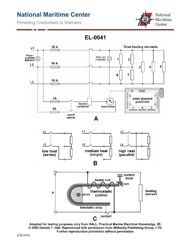
Question 427
Question: In the circuit 'B' of the illustration, what would be the result of the upper heating element being burned out and open circuited? Illustration EL-0041
A. Low heat (series) position would result in no heat at all. Medium heat (single) position would result in no heat at all. High heat (parallel) position would result in medium heat.
B. Low heat (series) position would result in low heat. Medium heat (single) position would result in medium heat. High heat (parallel) position would result in medium heat.
C. Low heat (series) position would result in no heat at all. Medium heat (single) position would result in medium heat. High heat (parallel) position would result in medium heat.
D. Low heat (series) position would result in low heat. Medium heat (single) position would result in low heat. High heat (parallel) position would result in medium heat.
The correct answer is A) Low heat (series) position would result in no heat at all. Medium heat (single) position would result in no heat at all. High heat (parallel) position would result in medium heat. This is correct because if the upper heating element in circuit 'B' is burned out and open circuited, it would break the series connection in the low heat position, resulting in no heat at all. Similarly, the single upper element would be open circuited in the medium heat position, again resulting in no heat. However, in the high heat (parallel) position, the lower heating element would still be functional, resulting in medium heat output. The other options are incorrect because they do not accurately describe the behavior of the circuit when the upper heating element is open circuited.
Question 440
Question: If the motor shown in the illustration will not start when the "off-run" switch is placed in the run position, which of the listed components should be checked FIRST? Illustration EL-0017
A. check the overload relay (OL) heaters for continuity, replace as necessary
B. check the overload relay for tripped condition, reset as necessary
C. check the disconnect switch open, open as necessary
D. check the main contactor coil for continuity, replace as necessary
The correct answer is B) check the overload relay for tripped condition, reset as necessary. The reasoning behind this is that if the motor will not start when the "off-run" switch is placed in the run position, the issue is likely related to the motor's overload protection circuit. The overload relay is designed to trip and interrupt the circuit if the motor draws excessive current, which could indicate an issue with the motor or the connected load. Checking the overload relay for a tripped condition and resetting it as necessary would be the logical first step to troubleshoot the problem. The other options are not as relevant in this scenario. Checking the overload relay heaters (A) or the main contactor coil (D) may be necessary if the overload relay is found to be faulty, but would not be the logical first step. Checking the disconnect switch (C) is not directly related to the issue of the motor not starting.
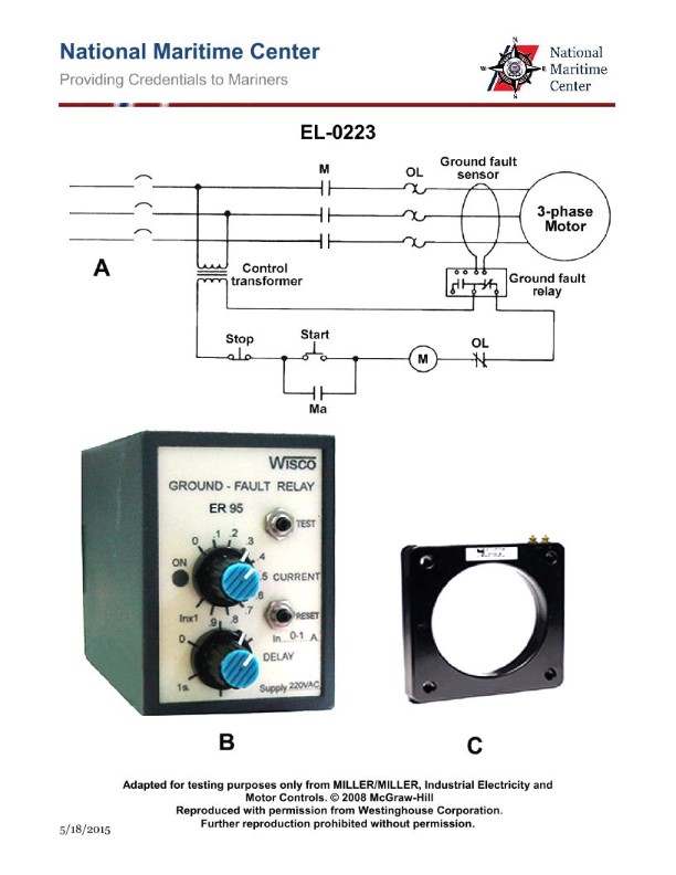
Question 441
Question: As shown in figure "C" of the illustrated typical ground fault sensor, what statement concerning its installation is true? Illustration EL-0223
A. Any two of the motor feeder conductors are connected to the two wire terminals in the upper right hand corner of the sensor as shown in the illustration and the ground fault relay sensor lead connections are passed through the window.
B. Any one of the motor feeder conductors is passed through the window and a connection is made between the ground fault relay sensor terminals and the two wire terminals in the upper right hand corner of the sensor as shown in the illustration.
C. All three of the motor feeder conductors are passed through the window and a connection is made between the ground fault relay sensor terminals and the two wire terminals in the upper right hand corner of the sensor as shown in the illustration.
D. Any two of the motor feeder conductors are passed through the window and a connection is made between the ground fault relay sensor terminals and the two wire terminals in the upper right hand corner of the sensor as shown in the illustration.
The correct answer is C. All three of the motor feeder conductors are passed through the window and a connection is made between the ground fault relay sensor terminals and the two wire terminals in the upper right hand corner of the sensor as shown in the illustration. This is because a ground fault sensor requires all current-carrying conductors associated with the circuit to pass through the sensor window in order to accurately detect any ground fault current. Having all three conductors pass through the sensor ensures the ground fault detection system can properly monitor the circuit. The other options are incorrect because they either do not pass all three conductors through the sensor window or do not properly connect the ground fault relay sensor terminals to the sensor, which would prevent the system from functioning as intended.
Question 444
Question: As shown in figure "A" and "B" of the illustration, the potable water pump is short- cycling by the action of the pressure switch as a result of an unusually high level in the potable water hydro-pneumatic header tank. What is most likely the cause? Illustration EL-0043
A. The pressure switch differential setting is set excessively high and the differential must be decreased.
B. The pressure switch range adjustment is set too low and must be set higher.
C. The potable water hydro-pneumatic header tank has too much compressed air and some must be bled off.
D. The potable water hydro-pneumatic header tank is in need of recharging with compressed air due to absorption of air into the water over time.
The correct answer is D) The potable water hydro-pneumatic header tank is in need of recharging with compressed air due to absorption of air into the water over time. This is the correct answer because the short-cycling of the potable water pump is likely caused by a loss of the proper air-to-water ratio in the hydro-pneumatic header tank. Over time, air can be absorbed into the water, reducing the air cushion and causing the pressure switch to cycle too frequently as the water level rises and falls. Recharging the tank with compressed air will restore the proper air-to-water ratio and stop the short-cycling. The other answer choices are incorrect because they do not address the underlying issue of the air-to-water ratio in the hydro-pneumatic tank. Adjusting the pressure switch differential or range would not fix the root cause of the problem.
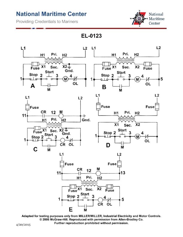
Question 446
Question: You are troubleshooting the control circuit shown in figure "A" of the illustration utilizing on-line techniques. With the start button depressed, the following readings are obtained with a voltmeter: (Refer to Illustration EL-0123
A. A
B. B
C. C
D. D
The correct answer is B. This is because when the start button is depressed, the voltmeter should read the voltage at point B, which is the input voltage to the control circuit. The other points (A, C, and D) are internal to the circuit and would not directly indicate the input voltage. The other options are incorrect because A, C, and D do not represent the input voltage to the circuit, which is the key parameter being measured when troubleshooting the control circuit.
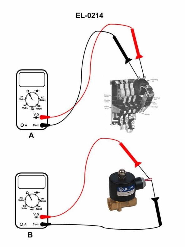
Question 448
Question: If a digital multimeter is set up as shown in figure "A" of the illustration to test an AC contactor coil, what would the display read if the coil is open-circuited? Illustration EL-0214
A. 0.03 ohms
B. 22 ohms
C. OL ohms
D. 110 V
The correct answer is C) OL ohms. When a digital multimeter is set up to measure resistance (ohms) and the circuit being tested is open-circuited, the multimeter will display "OL" (overload) to indicate that the resistance is out of the measurable range. This is because an open circuit has infinite resistance, which the multimeter cannot accurately measure. The other options are incorrect because: A) 0.03 ohms would be an extremely low resistance, which is not typical for an open-circuited AC contactor coil. B) 22 ohms would be a reasonable resistance for a functioning AC contactor coil, but not for an open-circuited one. D) 110 V is the voltage of the AC power source, not the resistance measurement.
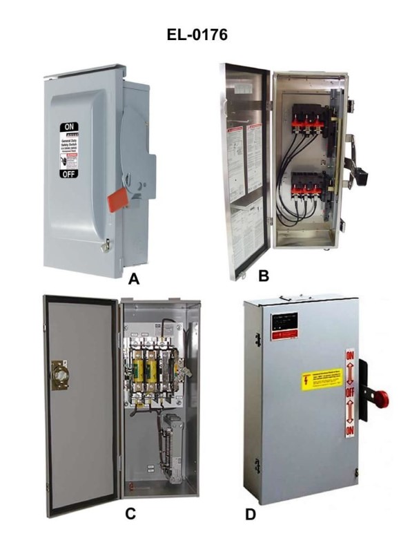
Question 451
Question: Which of the illustrated safety disconnect switches represents a double-throw switch? Illustration EL-0176
A. A and B
B. B and D
C. C and D
D. A and D
The correct answer is B) B and D. The illustration EL-0176 shows several examples of safety disconnect switches. A double-throw switch is one that can connect a circuit to either of two different terminals, effectively breaking the connection to one terminal while making a connection to the other. In the illustration, switches B and D are the only ones that clearly show this double-throw functionality, with three terminals that allow the switch to be connected to either the left or right side. The other switches, A and C, appear to be single-throw switches that simply open or close a single connection. Therefore, based on the definition of a double-throw switch and the visual characteristics of the switches shown, B and D are the correct options that represent a double-throw switch in this illustration.
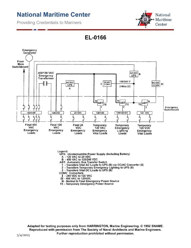
Question 454
Question: As shown in the illustrated one-line diagram of a two-tiered emergency power system for a passenger ship, what statement is true? Illustration EL-0166
A. On a restoration of normal ship's power, the final and temporary emergency loads power source is from the main switchboard.
B. On a restoration of normal ship's power, the temporary emergency loads power source is battery (from AC/DC UPS "A"), whereas the final emergency loads power source is from the main switchboard.
C. On a restoration of normal ship's power, the final emergency loads power source is battery (from AC/DC UPS "B"), whereas the temporary emergency loads power source is from the main switchboard.
D. On a restoration of normal ship's power, the final emergency loads power source is from the main switchboard, whereas the temporary emergency loads power source is battery (from AC/DC UPS "B").
The correct answer is A) On a restoration of normal ship's power, the final and temporary emergency loads power source is from the main switchboard. This is correct because the one-line diagram shows that the final and temporary emergency loads are both connected to the main switchboard. When normal ship's power is restored, the main switchboard would be the source of power for both the final and temporary emergency loads, as indicated in the diagram. The other options are incorrect because they do not accurately reflect the power sources shown in the one-line diagram for the restoration of normal ship's power. The diagram clearly shows the main switchboard as the source for both the final and temporary emergency loads.
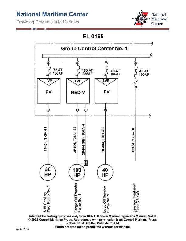
Question 457
Question: As shown in the illustration, which of the following pieces of equipment is provided with a remote push button station? Illustration EL-0165
A. Cargo Oil Transfer Pump No.1
B. Sewage Treatment Plant
C. Lube Oil Service Pump No.1
D. S.W. Cooling Circ. Pump No.1
The correct answer is A) Cargo Oil Transfer Pump No.1. The cargo oil transfer pump is typically provided with a remote push button station to allow the pump to be started and stopped from a location away from the pump itself. This is a safety feature that allows the operator to monitor and control the cargo transfer process from a safe distance. The other options, such as the sewage treatment plant, lube oil service pump, and seawater cooling circulation pump, do not typically require remote push button stations, as they are not directly involved in the cargo transfer process where remote control is necessary for safety.
Question 464
Question: Which of the schematic symbols shown in the illustration represents a normally closed float level switch? Illustration EL-0059
A. 1
B. 3
C. 4
D. 6
The correct answer is B) 3. The schematic symbol for a normally closed float level switch is represented by option B) 3 in the illustration EL-0059. This is the correct answer because a normally closed float level switch is a type of switch that is closed when the liquid level is at or below the switch's set point, and opens when the liquid level rises above the set point. The other answer choices do not represent a normally closed float level switch. Options A) 1 and D) 6 may represent other types of electrical components, but not a normally closed float level switch. Option C) 4 appears to be a symbol for a different type of switch or control device.
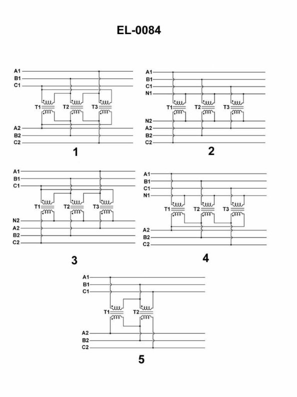
Question 465
Question: Which of the listed figures shown in the illustration represents a three phase transformer connected in a wye-delta configuration? Illustration EL-0084
A. 1
B. 2
C. 3
D. 4
The correct answer is D. The illustration EL-0084 depicts a three-phase transformer in a wye-delta configuration, which is represented by figure 4. In a wye-delta configuration, the primary windings are connected in a wye (Y) configuration, while the secondary windings are connected in a delta (Δ) configuration. This type of transformer connection is commonly used to step down voltage levels and provide a neutral point for the system. The other answer choices (A, B, and C) represent different transformer configurations, such as three single-phase transformers or a three-phase transformer in a delta-delta or wye-wye configuration, which are not the correct representation of a wye-delta transformer.
Question 467
Question: What is the purpose for the device shown in figure "B" of the illustration in terms of its relationship with the load? Illustration EL-0083
A. it functions as a filter
B. it functions to step-up voltage
C. it functions to step-down voltage
D. it functions as a ground isolator
The correct answer is C) it functions to step-down voltage. The device shown in figure "B" of the illustration EL-0083 is likely a transformer, which is used to step-down the voltage from a higher level to a lower level. This is necessary to ensure the electrical load receives the appropriate voltage for its operation, as many electrical devices require a lower voltage than the main power supply. The other answer choices are incorrect because: A) a filter is used to remove unwanted frequency components, not to adjust voltage levels; B) a step-up transformer would increase the voltage, which is the opposite of what is required for the load; and D) a ground isolator is used to separate the ground of two circuits, not to adjust voltage.
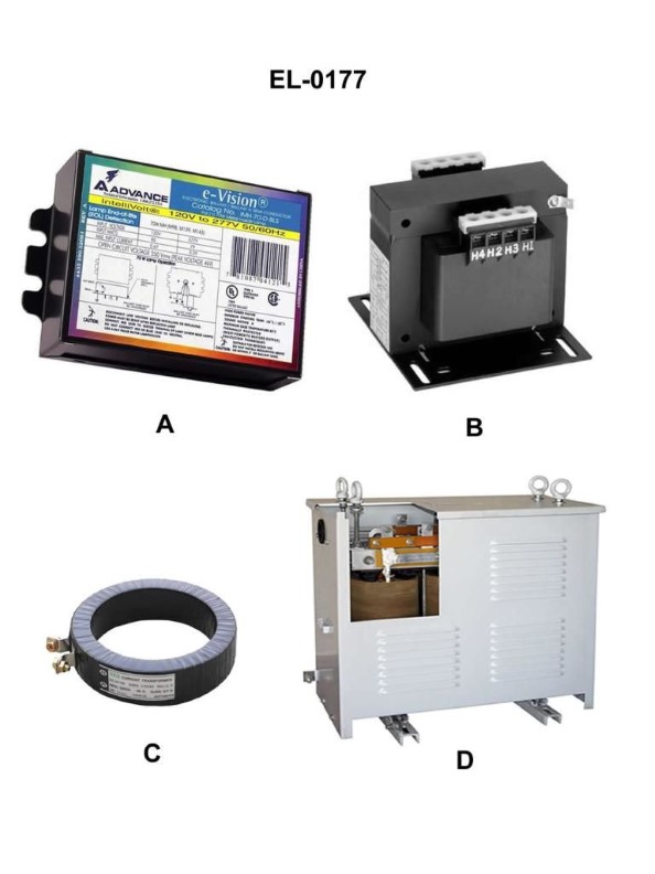
Question 469
Question: Which of the following is a pictured three phase power transformer, usually used to step-down line voltage for supplying reduced voltage lighting circuits? Illustration EL-0177
A. A
B. B
C. C
D. D
The correct answer is D. The illustration EL-0177 depicts a three-phase power transformer, which is typically used to step down line voltage for supplying reduced voltage lighting circuits. These transformers are commonly employed in Coast Guard vessels and facilities to distribute power efficiently and safely. The other options (A, B, and C) may represent different types of electrical equipment, but they do not match the specific description provided in the question for the illustrated three-phase power transformer.
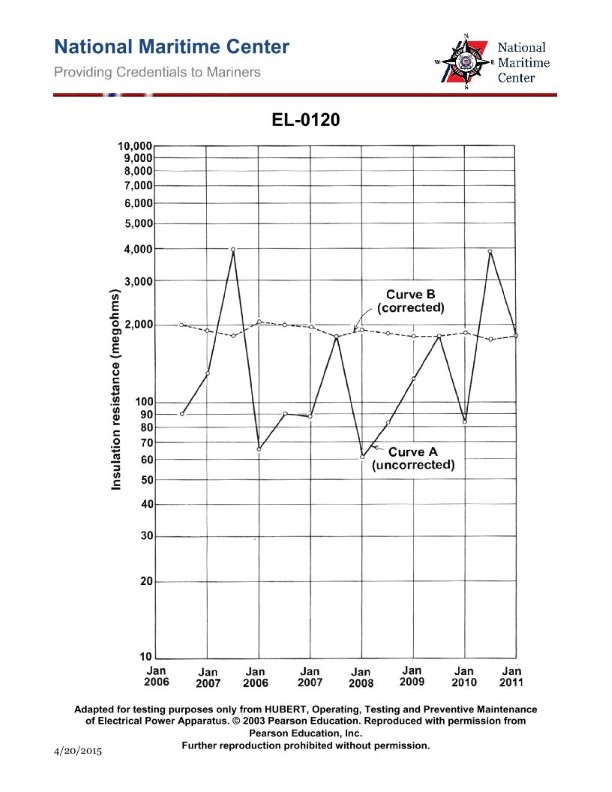
Question 474
Question: As shown in the illustrated plots of uncorrected and temperature corrected insulation resistance readings for a particular piece of equipment, at what point in time should the equipment have been refurbished or replaced? Illustration EL-0120
A. 2006
B. 2008
C. 2010
D. no refurbishment or replacement was necessary through 2011
The correct answer is D) no refurbishment or replacement was necessary through 2011. The illustrated plots show that the insulation resistance, even when corrected for temperature, remained above the minimum acceptable level through 2011. According to Coast Guard regulations, there is no requirement to refurbish or replace equipment as long as the insulation resistance stays within acceptable limits. Since the insulation resistance did not drop below the minimum threshold during the time period shown, no refurbishment or replacement was necessary. The other answer choices are incorrect because they suggest the equipment needed to be serviced at earlier time points, even though the data indicates the insulation resistance was maintained at safe levels.
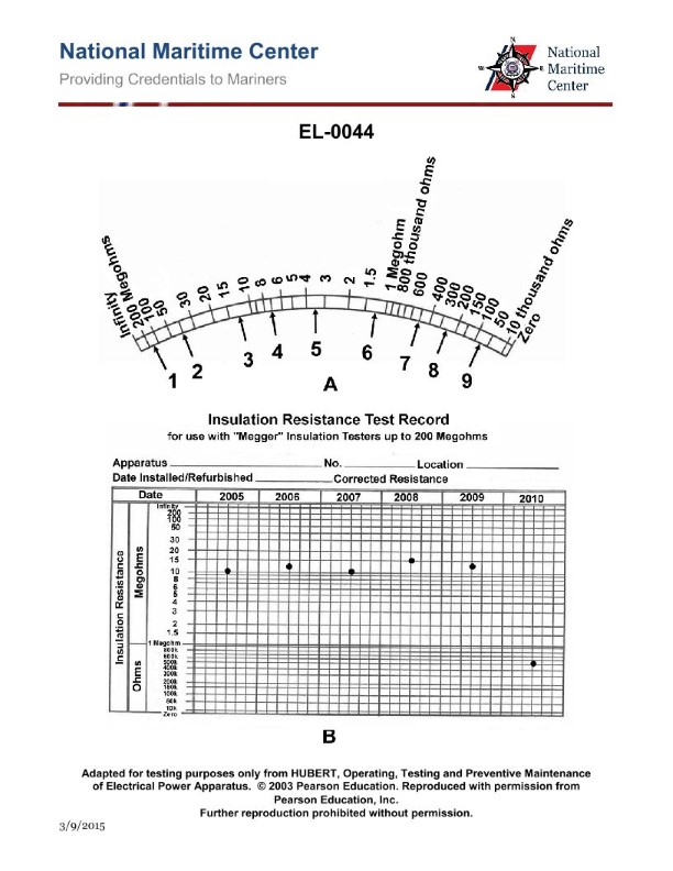
Question 475
Question: What is the resistance reading at "2" on the megger scale shown in figure "A" of the illustration? Illustration EL-0044
A. 40 ohms
B. 400 ohms
C. 40,000 ohms
D. 40 megohms
The correct answer is D) 40 megohms. The megger scale shown in figure "A" of the illustration EL-0044 indicates that the resistance reading at position "2" on the scale corresponds to 40 megohms. This is because a megger is a special type of ohmmeter used to measure very high resistance values, typically in the range of megohms (millions of ohms). The other answer choices are incorrect because 40 ohms (choice A) and 400 ohms (choice B) are too low for a megger reading, and 40,000 ohms (choice C) is too high for the "2" position on the scale shown in the illustration.
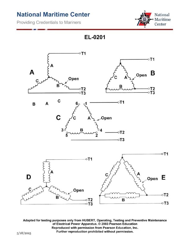
Question 485
Question: As shown in figure "B" of the illustration, with a digital multimeter set up as an ohmmeter, what set of readings would be consistent with an open in a phase of the single circuit, delta-connected stator windings as shown? Illustration EL-0201
A. T1 to T2: "1.8 ohms"; T2 to T3: "OL ohms"; T3 to T1: "1.8 ohms"
B. T1 to T2: "1.8 ohms"; T2 to T3: "3.6 ohms"; T3 to T1: "1.8 ohms"
C. T1 to T2: "3.6 ohms"; T2 to T3: "1.8 ohms"; T3 to T1: "1.8 ohms"
D. T1 to T2: "OL ohms"; T2 to T3: "1.8 ohms"; T3 to T1: "1.8 ohms"
The correct answer is C: T1 to T2: "3.6 ohms"; T2 to T3: "1.8 ohms"; T3 to T1: "1.8 ohms". In a delta-connected stator winding, an open in one phase will result in the other two phases appearing in series, leading to a total resistance of 3.6 ohms between the two healthy phases (T1 to T2). The resistance between the healthy phase and the open phase (T2 to T3 and T3 to T1) will be half of the total, or 1.8 ohms. The other options are incorrect because they do not represent the expected resistance readings for an open in a single phase of a delta-connected stator winding.
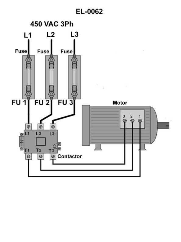
Question 489
Question: In order to definitively determine whether or not fuse "2", shown in the illustration is blown using an on-line testing technique, across what points would you connect the voltmeter leads? Illustration EL-0062
A. the bottom of fuse "2" to the top of either fuse "1 or 3"
B. the bottom of fuse "2" to the bottom of either fuse "1 or 3"
C. the top of fuse "2" to the bottom of either fuse "1 or 3"
D. the top of fuse "2" to the top of either fuse "1 or 3"
The correct answer is A) the bottom of fuse "2" to the top of either fuse "1 or 3". To definitively determine if fuse "2" is blown, you would need to measure the voltage drop across the fuse. By connecting the voltmeter leads from the bottom of fuse "2" to the top of either fuse "1 or 3", you can directly measure the voltage across fuse "2". If the voltage reading is zero, then fuse "2" is blown. The other options would not provide a direct measurement of the voltage drop across fuse "2" and would therefore not be the best way to determine if it is blown.
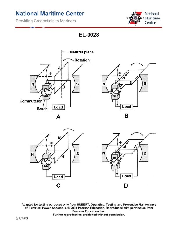
Question 512
Question: In which figure shown in the illustration will the highest voltage be induced? Illustration EL-0028
A. figure "A" only
B. figure "B" only
C. both figures "A" and "C"
D. both figures "B" and "D"
The correct answer is D) both figures "B" and "D". The reason for this is that figures "B" and "D" depict a changing magnetic field, which will induce the highest voltage according to Faraday's law of electromagnetic induction. In these figures, the magnetic field is changing due to the movement of the conductor, leading to a higher induced voltage compared to the stationary conductor in figures "A" and "C". The other options are incorrect because figure "A" has a stationary conductor, and figure "C" has a changing magnetic field but no conductor, both of which would result in a lower induced voltage compared to figures "B" and "D".
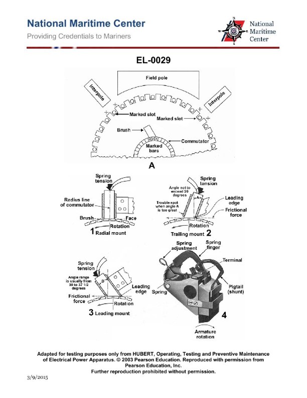
Question 513
Question: As shown in the illustration, which brush holder would be appropriate to use in a bidirectional motor? Illustration EL-0029
A. trailing mount only
B. both leading and trailing mount
C. leading mount only
D. radial mount
The correct answer is D) radial mount. In a bidirectional motor, the brush holder needs to be able to accommodate the motor's ability to rotate in both forward and reverse directions. A radial mount brush holder is the appropriate choice, as it allows the brushes to maintain contact with the commutator in either direction of rotation. The other options would not be suitable for a bidirectional motor. A trailing mount brush holder would only work in one direction, while a leading mount or both leading and trailing mount would not provide the necessary flexibility for the brushes to maintain contact in both directions of rotation.
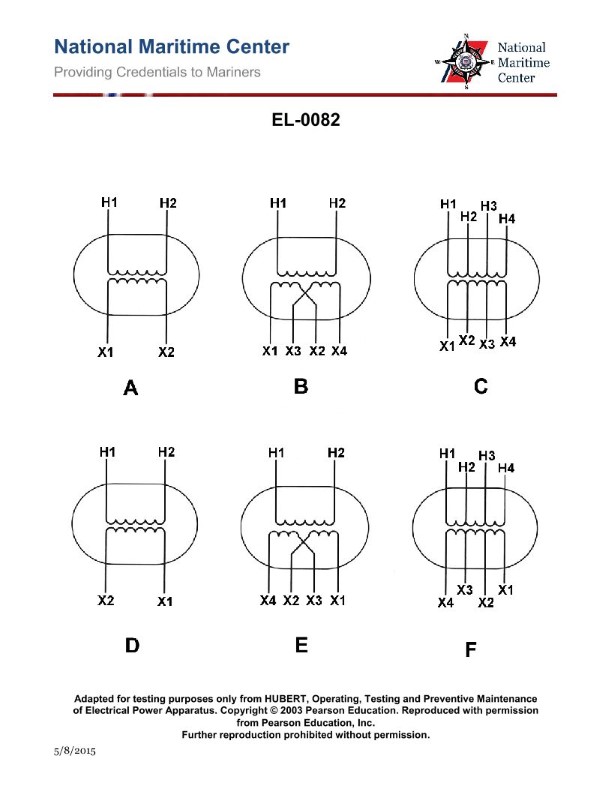
Question 519
Question: The turns ratio of the step-down transformer with dual voltage secondary as shown in figure "B" of the illustration is two to one (total). If 440 volts were applied to terminals 'H1' and 'H2', what would be measured across 'X1-X3' and 'X2-X4' assuming that the secondary windings are connected in parallel? Illustration EL-0082
A. 55 volts
B. 110 volts
C. 220 volts
D. 880 volts
The correct answer is B) 110 volts. The explanation is as follows: 1. The turns ratio of the step-down transformer with dual voltage secondary is two to one (total). This means that the secondary windings have half the number of turns as the primary winding. 2. Since the primary voltage is 440 volts, and the turns ratio is 2:1, the secondary voltage will be 440 / 2 = 220 volts. However, the secondary windings are connected in parallel, so the measured voltage across 'X1-X3' and 'X2-X4' will be 220 volts divided by 2, which equals 110 volts. 3. The other options are incorrect because 55 volts (A) is half of the correct answer, 220 volts (C) is the voltage of the individual secondary windings, and 880 volts (D) is twice the primary voltage, which is not the correct secondary voltage.
Question 520
Question: In figure "2" of the diagram shown in the illustration, the three phase power transformer has a step-down turns ratio of four to one. If a three-phase 440 volt supply is connected to terminals 'A1-B1-C1’, what voltage should develop across terminals 'A2-B2-C2'? Illustration EL-0084
A. 64 volts
B. 110 volts
C. 190 volts
D. 762 volts
The correct answer is B) 110 volts. The key information provided is that the three-phase power transformer in the diagram has a step-down turns ratio of 4:1. This means that for every 4 turns on the primary winding (connected to the 440 volt supply), there is 1 turn on the secondary winding. With a 4:1 turns ratio, the output voltage on the secondary winding (terminals A2-B2-C2) will be 1/4 of the input voltage of 440 volts, which equals 110 volts. This is the correct answer. The other options are incorrect because they do not correctly apply the 4:1 step-down turns ratio to calculate the expected secondary voltage.
Question 522
Question: A load is connected across the secondary of the step-up transformer shown in figure "B" of the illustration and the current drawn by the load is 10 amps. If the turns ratio is 1 to 10 and the input voltage is 110 VAC, what will be the current drawn by the primary? Illustration EL-0055
A. 1 amp
B. 10 amps
C. 100 amps
D. 1000 amps
The correct answer is C) 100 amps. In a step-up transformer, the turns ratio is inversely proportional to the current ratio. Since the turns ratio is 1 to 10, the current in the primary will be 10 times less than the current in the secondary. With a secondary current of 10 amps, the primary current will be 10 times less, which is 100 amps. The other options are incorrect because: A) 1 amp is too low, as the primary current should be 100 times the secondary current. B) 10 amps is the secondary current, not the primary current. D) 1000 amps is too high, as the primary current should be 10 times the secondary current.
Question 532
Question: As shown in the illustrated DC machine which is configured as a generator, what type of machine is illustrated in terms of the configuration of the windings? Illustration EL-0052
A. series wound
B. cumulatively compound wound
C. differentially compound wound
D. shunt wound
The correct answer is D) shunt wound. The illustration EL-0052 shows a DC machine configured as a generator, which has the field windings connected in parallel (shunt) with the armature windings. This configuration is characteristic of a shunt wound DC machine, where the field windings are supplied with a separate current path from the armature. The other options are incorrect because: A) a series wound machine has the field windings connected in series with the armature, B) a cumulatively compound wound machine has both series and shunt field windings, and C) a differentially compound wound machine has series and shunt field windings connected to oppose each other.
Question 536
Question: As shown in the illustration, which brush holder is of the reaction type? Illustration EL-0029
A. 1
B. 2
C. 3
D. 4
The correct answer is D. The brush holder labeled 4 in the illustration is of the reaction type. The reaction type brush holder is used in DC generators and motors, where the brushes are held in place by a spring that applies pressure against the commutator. This allows the brushes to follow the commutator as it wears down, maintaining constant contact. The other brush holders labeled 1, 2, and 3 are not of the reaction type, as they do not use a spring-loaded mechanism to maintain brush contact with the commutator.
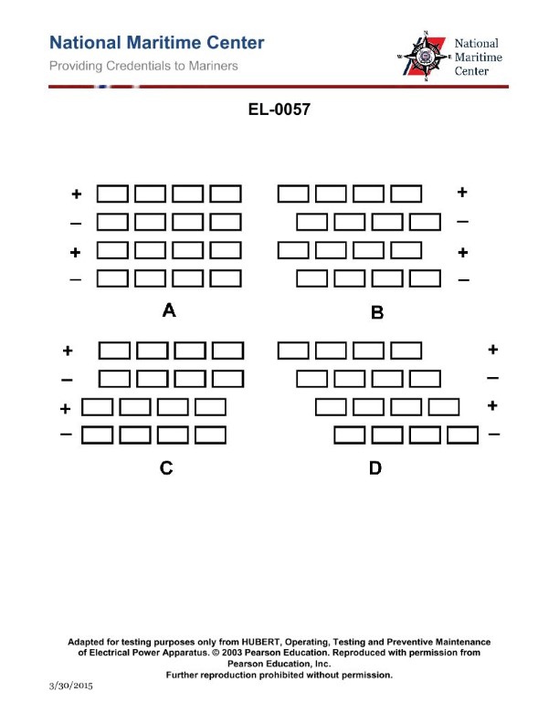
Question 537
Question: Which of the diagrams shown in the illustration depicts the proper method of aligning brushes on a commutator for a DC machine? Illustration EL-0057
A. A
B. B
C. C
D. D
The correct answer is C. The diagram labeled C in the illustration EL-0057 depicts the proper method of aligning brushes on a commutator for a DC machine. The brushes should be aligned with the neutral axis, which is the position where the armature coils are not generating any voltage. This alignment ensures optimal performance and minimizes sparking at the commutator. The other answer choices are incorrect because they do not show the brushes aligned with the neutral axis, which is the proper configuration for a DC machine commutator.