Pass Your Coast Guard Licensing Exams!
Study offline, track your progress, and simulate real exams with the Coast Guard Exams app
General Subjects - Assistant
153 images
Question 2
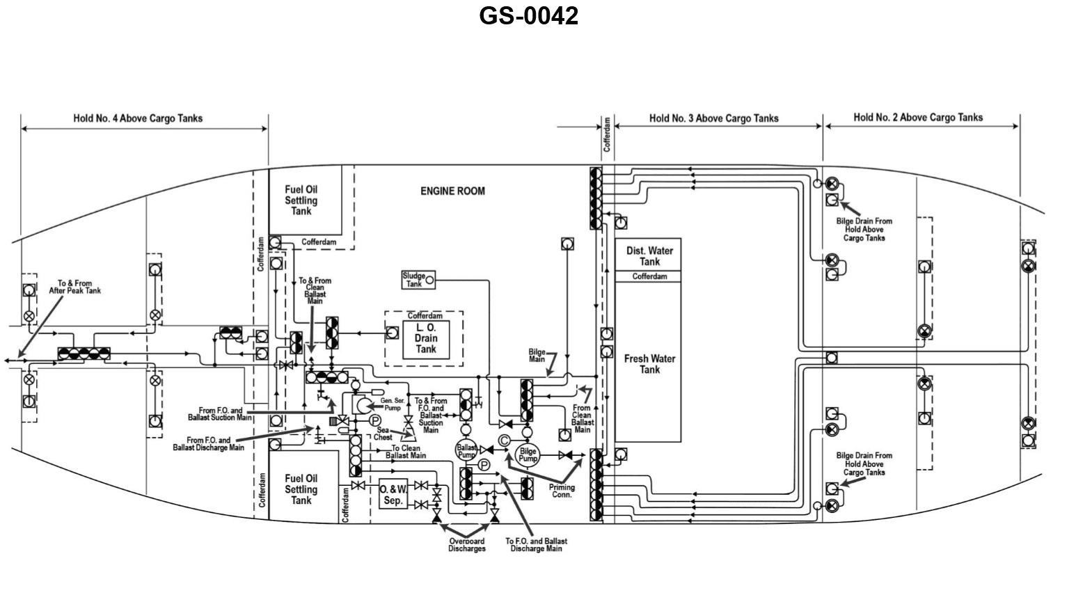
Question: In order to take suction on the lube oil drain tank cofferdam with the bilge pump shown in the illustration, how many suction side valves must be open? Illustration GS-0042
A. One
B. Two
C. Three
D. Four
The correct answer is B) Two. To take suction on the lube oil drain tank cofferdam with the bilge pump, two suction side valves must be open. This is because the bilge pump system typically has two suction side valves - one valve to draw from the lube oil drain tank cofferdam, and another valve to draw from the general bilge system. Both of these valves need to be open in order for the bilge pump to take suction from the lube oil drain tank cofferdam. The other answer choices are incorrect because one valve would not be enough to draw from the cofferdam, three or four valves would be unnecessary for this specific task.
Question 9
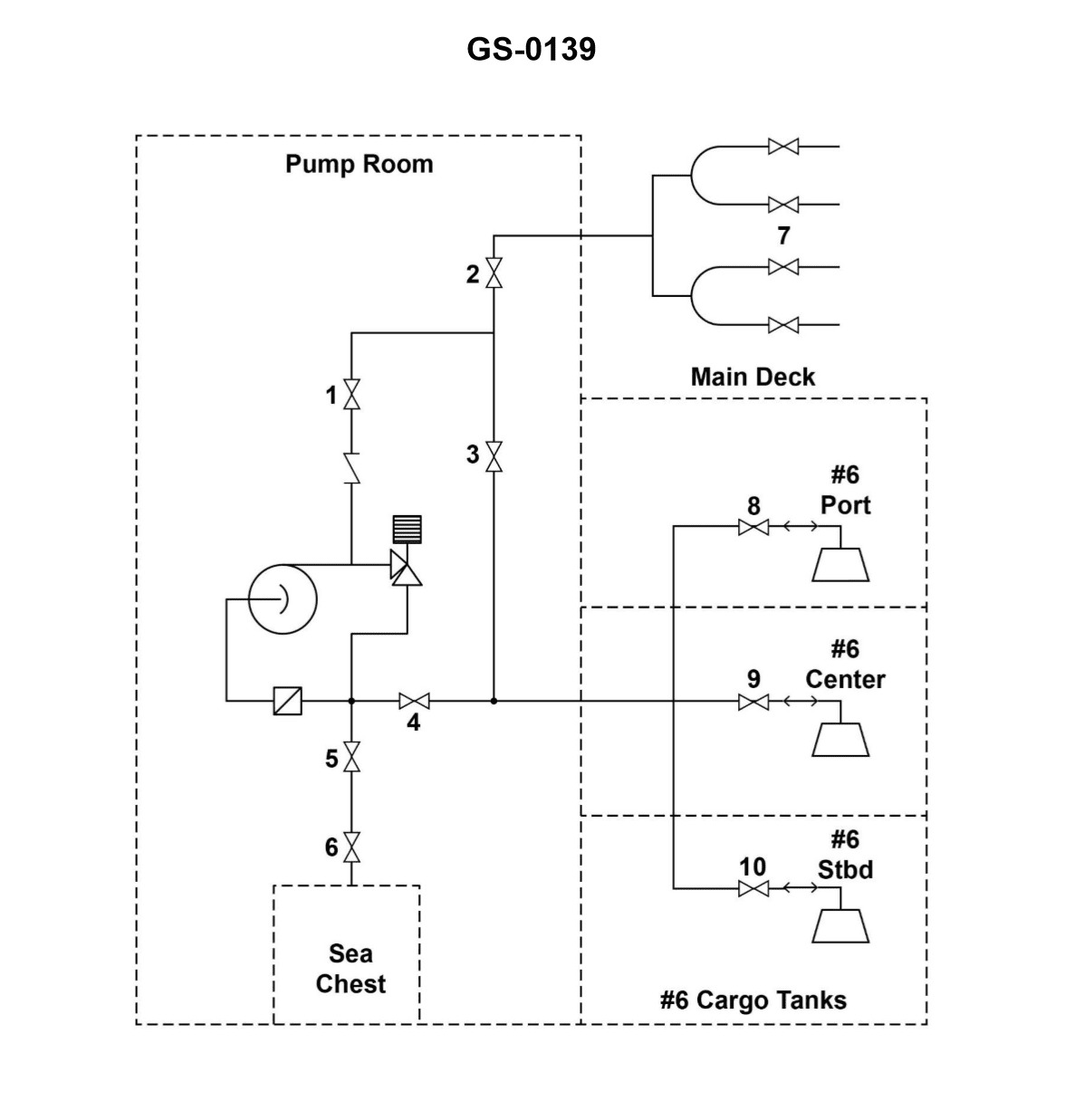
Question: Salt water ballast is to be discharged into the No.6 port and starboard wing tanks. Which combination of valves, illustrated, must be opened, and which valves should be closed? Illustration GS-0139
A. 1, 2, 5 and 6 open; 4, 7, 8 and 9 closed.
B. 1, 2, 7 and 9 open; 3, 4, 5, 6, 8 and 10 closed.
C. 1, 3, 5, 6, 8 and 10 open; 2, 4, 7 and 9 closed.
D. 3, 4, 7 and 9 open; 1, 2, 5, 6 and 10 closed.
The correct answer is C) 1, 3, 5, 6, 8 and 10 open; 2, 4, 7 and 9 closed. To discharge the salt water ballast into the No.6 port and starboard wing tanks, the valves that need to be opened are 1, 3, 5, 6, 8 and 10. This allows the ballast water to flow into the designated tanks. The valves that need to be closed are 2, 4, 7 and 9 to prevent the ballast water from flowing into the wrong tanks or areas. The other options are incorrect because they do not correctly identify the specific valves that need to be opened and closed to discharge the ballast water into the No.6 port and starboard wing tanks.
Question 20
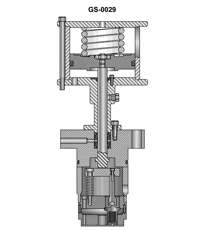
Question: The device shown in the illustration is used to _______________. Illustration GS-0029
A. reduce the pressure in the ship's service air system
B. maintain correct tension on the drive belts while the compressor is in operation
C. grind sewage prior to entering the sewage treatment plant
D. unload the cylinders of an air compressor
The correct answer is D) unload the cylinders of an air compressor. The device shown in the illustration is an air compressor unloader, which is used to release the pressure in the cylinders of an air compressor when it is not in operation. This prevents the compressor from building up excessive pressure, which could damage the system. The other answer choices are incorrect because: A) is not the function of this device, B) refers to a different type of component, and C) describes a function unrelated to an air compressor.
Question 49
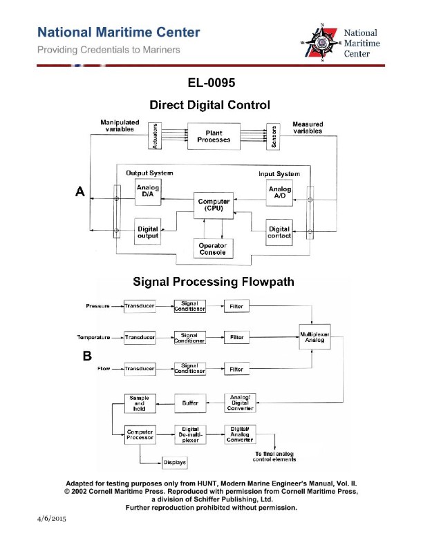
Question: As shown in figure "A" of the illustrated block diagram of a central operating system configured for direct digital control, what does the output system block "ANALOG D/A" represent? Illustration EL-0095
A. It receives digital outputs from the CPU and conditions these as digital signals for transmission to digital actuators.
B. It receives digital outputs from the CPU and converts these to analog signals for transmission to analog actuators.
C. It receives analog outputs from the CPU and converts these to digital signals for transmission to digital actuators.
D. It receives analog outputs from the CPU and conditions these as analog signals for transmission to analog actuators.
The correct answer is B) It receives digital outputs from the CPU and converts these to analog signals for transmission to analog actuators. The "ANALOG D/A" block in the illustrated diagram represents a digital-to-analog converter (D/A or DAC) that takes the digital outputs from the central processing unit (CPU) and converts them into analog signals. These analog signals are then transmitted to analog actuators or control devices, which require an analog input to operate. The other answer choices are incorrect because A) describes a function of a digital output module, C) describes an analog-to-digital converter (which would convert analog signals to digital), and D) describes the function of an analog output module, not a digital-to-analog converter.
Question 54
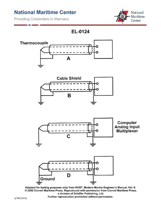
Question: Which of the following illustrations represents the proper method of circuit grounding for a low level analog signal cable? Illustration EL-0124
A. A
B. B
C. C
D. D
The correct answer is A. Illustration EL-0124 depicts the proper method of circuit grounding for a low-level analog signal cable, which is to connect the cable shield to the system ground at one end only. This approach helps to minimize ground loop issues and signal interference, as per the best practices for analog signal transmission. The other options (B, C, and D) would not be considered the proper grounding method, as they either leave the shield unconnected or ground it at both ends, which can lead to ground loop problems and signal degradation.
Question 56
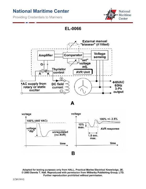
Question: As shown in figure "A" of the illustration, what statement is true concerning the voltage sensing unit? Illustration EL-0066
A. The voltage sensor delivers an AC signal voltage equal in magnitude to the alternator output voltage to the comparator.
B. The voltage sensor delivers a relatively low value of DC signal voltage proportional to the alternator output voltage to the comparator.
C. The voltage sensor delivers a relatively low value of single phase AC signal voltage proportional to the alternator output voltage to the comparator.
D. The voltage sensor delivers a DC signal voltage equal in magnitude to the alternator output voltage to the comparator.
The correct answer is B) The voltage sensor delivers a relatively low value of DC signal voltage proportional to the alternator output voltage to the comparator. The voltage sensing unit is designed to convert the high alternator output voltage (typically 12V or 24V) to a lower DC voltage signal that can be processed by the comparator circuit. This lower DC voltage signal is proportional to the alternator output voltage, allowing the comparator to monitor and regulate the charging system. The other options are incorrect because: A) the voltage sensor does not deliver an AC signal, C) the voltage sensor does not deliver a single-phase AC signal, and D) the voltage sensor does not deliver a DC signal equal in magnitude to the alternator output voltage, which would be too high for the comparator to process.
Question 61
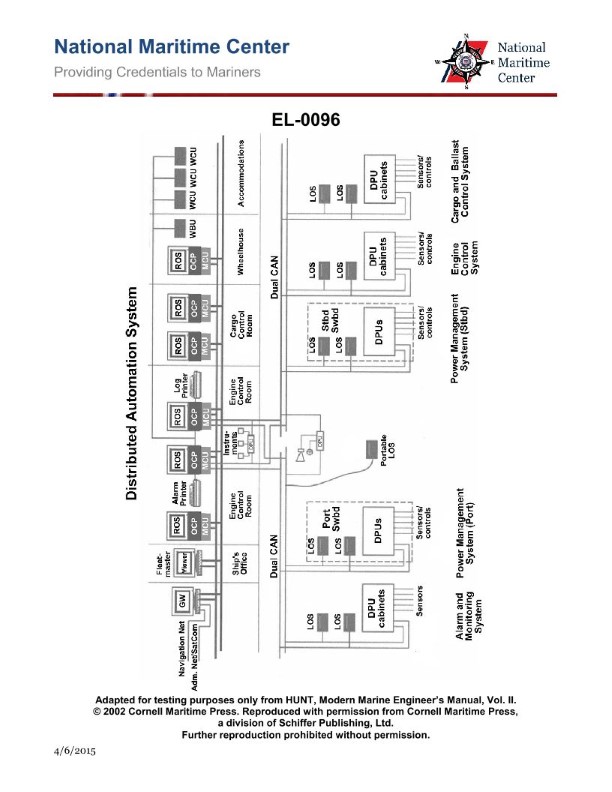
Question: As shown in the illustrated block diagram for a distributed automation system, what statement is true concerning the units labeled "ROS" which are remote operating system workstations? Illustration EL-0096
A. Operator access to control functions among the various ROS locations differ depending on system configuration and need.
B. The ROS located in the ship's office is designated as the master ROS.
C. The ROS located in the wheelhouse is designated as the master ROS.
D. Operator access to control functions among the various ROS locations are all identical.
The correct answer is A) Operator access to control functions among the various ROS locations differ depending on system configuration and need. This is correct because in a distributed automation system, the remote operating system (ROS) workstations are typically configured to provide different levels of access and control depending on their location and the specific operational requirements. The system design allows for tailoring the operator access and control capabilities of each ROS to match the responsibilities and needs of that particular work area. The other options are incorrect because they make blanket statements about the ROS designations or access levels, which may not accurately reflect the flexibility and customization inherent in a distributed automation system design.
Question 63
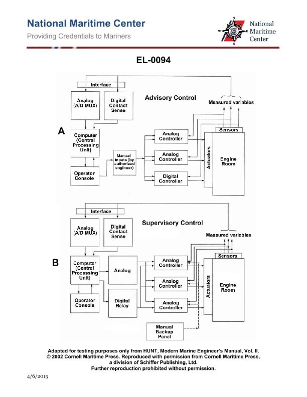
Question: As shown in figure "B" of the illustrated block diagram for a central operating system configured for supervisory control, what is becoming the industry standard for transmission of analog signals for a measured variable? Illustration EL-0094
A. 1 volt to 5 volts
B. -10 volts to +10 volts
C. 4 milliamps to 20 milliamps
D. 10 milliamps to 50 milliamps
The correct answer is C) 4 milliamps to 20 milliamps. This is the industry standard for transmission of analog signals for a measured variable in a central operating system configured for supervisory control. The 4-20 mA current loop is a widely adopted standard in process control and industrial automation applications, as it provides a reliable and noise-resistant method of transmitting analog signals over long distances. The other options are incorrect because they do not represent the established industry standard. Option A (1 volt to 5 volts) and Option B (-10 volts to +10 volts) are less common voltage-based standards, while Option D (10 milliamps to 50 milliamps) is not a recognized standard for analog signal transmission.
Question 64
Question: As shown in figure "B" in the illustrated block diagram of a central operating system configured for supervisory control, what is the function of the block "ANALOG (A-D MUX)"? Illustration EL-0094
A. A high-speed solid-state switching device called a multiplexer capable of scanning a large number of analog sensors in a short period of time and converting these to signals to digital values for processing by the CPU.
B. A low-speed solid-state switching device called a multiplexer capable of scanning a small number of analog sensors in a long period of time and converting these to signals to digital values for processing by the CPU.
C. A low-speed solid-state switching device called a multiplexer capable of scanning a small number of digital sensors in a long period of time and converting these to signals to analog values for processing by the CPU.
D. A high-speed solid-state switching device called a multiplexer capable of scanning a large number of digital sensors in a short period of time and converting these to signals to analog values for processing by the CPU.
The correct answer is A. The "ANALOG (A-D MUX)" block in the illustrated block diagram of a central operating system configured for supervisory control represents a high-speed solid-state switching device called a multiplexer. This multiplexer is capable of scanning a large number of analog sensors in a short period of time and converting these analog signals to digital values for processing by the CPU. The other answer choices are incorrect because they describe different types of multiplexer devices that do not match the characteristics of the "ANALOG (A-D MUX)" block as depicted in the diagram. Specifically, options B, C, and D describe low-speed, small-scale, or digital-to-analog multiplexer devices, which do not align with the high-speed, large-scale, and analog-to-digital functionality of the block in question.
Question 65
Question: As shown in figure "A" of the illustrated block diagram of a central operating system configured for direct digital control, what does the output system block "DIGITAL CONTACT" represent? Illustration EL-0095
A. It receives analog outputs from the analog device sensors and conditions these as analog signals for CPU processing.
B. It receives digital outputs from the binary device sensors and converts these to analog signals for CPU processing.
C. It receives analog outputs from the analog device sensors and converts these to digital signals for CPU processing.
D. It receives digital outputs from the binary device sensors and conditions these as digital signals for CPU processing.
The correct answer is D) It receives digital outputs from the binary device sensors and conditions these as digital signals for CPU processing. This is the correct answer because the "DIGITAL CONTACT" output system block represents the interface that receives digital signals from binary device sensors (e.g., on/off switches, relays) and conditions them as digital signals for processing by the central processing unit (CPU) in the digital control system. The other options are incorrect because they do not accurately describe the function of the "DIGITAL CONTACT" block. Option A refers to analog outputs, Option B describes converting digital to analog signals, and Option C describes converting analog to digital signals, which are not the functions of the "DIGITAL CONTACT" block as depicted in the illustrated block diagram.
Question 66
Question: As shown in the illustrated block diagram for a distributed automation system, what statement is true concerning the area networks? Illustration EL-0096
A. The LAN is a dual redundant network and the partitioned CAN is also a dual redundant network, with no interconnectivity between the two networks.
B. The LAN is a dual redundant network and the partitioned CAN is also a dual redundant network, with both networks being interconnected.
C. The LAN is a single non-redundant network and the partitioned CAN is a dual redundant network, with both networks being interconnected.
D. The LAN is a single non-redundant network and the partitioned CAN is a dual redundant network, with no interconnectivity between the two networks.
The correct answer is B. The explanation is as follows: 1) The statement is true that the LAN is a dual redundant network and the partitioned CAN is also a dual redundant network, with both networks being interconnected. 2) This is correct because the block diagram illustrates a distributed automation system with two separate area networks - a dual redundant LAN and a dual redundant partitioned CAN - that are interconnected, allowing communication between the two networks. 3) The other options are incorrect because they do not accurately describe the interconnectivity between the two redundant networks as shown in the diagram. 4) In summary, the key aspects that make option B the correct answer are the dual redundancy of both networks and the interconnectivity between them, as depicted in the illustrated block diagram.
Question 67
Question: As shown in the illustrated block diagram for a distributed automation system, what statement is true concerning the data communication pathways labeled "Dual CAN"? Illustration EL-0096
A. These are control area networks providing supply and return pathways for communication.
B. These are control area networks providing redundancy so as to maintain communications despite a bus failure.
C. These are communication access nodes providing redundancy so as to maintain communications despite a node failure.
D. These are communication access nodes providing supply and return pathways for communication.
The correct answer is B) These are control area networks providing redundancy so as to maintain communications despite a bus failure. The "Dual CAN" pathways in the illustrated block diagram represent redundant control area networks (CAN bus) that provide backup communication channels. This redundancy ensures that communication can be maintained even if one of the CAN buses fails, ensuring the overall reliability and resilience of the distributed automation system. The other answer choices do not accurately describe the purpose and function of the "Dual CAN" pathways as presented in the diagram.
Question 68
Question: As shown in figure "A" of the illustrated block diagram of a central operating system configured for direct digital control, what does the output system block "ANALOG A/D" represent? Illustration EL-0095
A. It receives analog outputs from the analog device sensors and converts these to digital signals for CPU processing.
B. It receives digital outputs from the binary device sensors and conditions these as digital signals for CPU processing.
C. It receives digital outputs from the binary device sensors and converts these to analog signals for CPU processing.
D. It receives analog outputs from the analog device sensors and conditions these as analog signals for CPU processing.
The correct answer is A) It receives analog outputs from the analog device sensors and converts these to digital signals for CPU processing. This is correct because the "ANALOG A/D" block in the illustrated block diagram represents the analog-to-digital conversion process. Analog sensors produce continuous signals, and the A/D converter takes these analog inputs and converts them into digital signals that can be processed by the central processing unit (CPU). The other options are incorrect because they do not accurately describe the function of the "ANALOG A/D" block. Option B refers to binary (digital) sensors, while option C describes converting digital signals to analog, which is the opposite of what the A/D converter does. Option D describes conditioning analog signals, but does not mention the conversion to digital format.
Question 69
Question: As shown in figure "B" of the illustrated block diagram of a central operating system configured for supervisory control, which statement is true concerning the block "COMPUTER" with respect to closed-loop control processes? Illustration EL-0094
A. The computer normally has no role in the various closed-loop control processes. It is only used for backup control purposes.
B. The computer has no role in the various closed-loop control processes regardless of the control mode.
C. The computer provides the set point input data to the analog controllers, but the analog controllers actually control the closed-loop processes.
D. The computer provides the set point input data to the process control loop, as well as the measured variable data. The analog controllers are only used for manual backup control.
The correct answer is C) The computer provides the set point input data to the analog controllers, but the analog controllers actually control the closed-loop processes. This is the correct answer because in a central operating system configured for supervisory control, as shown in the illustrated block diagram, the computer serves as the central supervisory control element. It provides the set point input data to the analog controllers, which then use that information to directly control the various closed-loop processes. The other options are incorrect because the computer does play an active role in the closed-loop control processes (not just for backup purposes), and the analog controllers are the primary control elements, not just used for manual backup.
Question 70
Question: As shown in figure "A" of the illustrated block diagram of a central operating system configured for direct digital control, what does the output system block "ANALOG D/A" represent? Illustration EL-0095
A. It receives analog outputs from the CPU and converts these to digital signals for transmission to the digital actuators.
B. It receives analog outputs from the CPU and conditions these to analog signals for transmission to the analog actuators.
C. It receives digital outputs from the CPU and converts these to analog signals for transmission to the analog actuators.
D. It receives digital outputs from the CPU and conditions these to digital signals for transmission to the digital actuators.
The correct answer is C) It receives digital outputs from the CPU and converts these to analog signals for transmission to the analog actuators. The "ANALOG D/A" block in the illustrated central operating system diagram represents a digital-to-analog (D/A) converter. This component is responsible for taking the digital output signals from the central processing unit (CPU) and converting them into analog signals that can be transmitted to analog actuators for control of the system. The other answer choices are incorrect because they do not accurately describe the function of the "ANALOG D/A" block. Option A describes an analog-to-digital (A/D) conversion, which is the opposite of what this block does. Option B and D involve conditioning the signals, but do not specify the conversion from digital to analog as the correct answer does.
Question 91
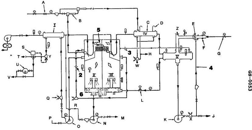
Question: A high reading is only indicated at the salinity cells labeled "W" and "6" shown in the illustration. This would be the probable result of _______________. Illustration GS-0053
A. a tube leak in item 'IV', which contributes to a surging absolute pressure in "III"
B. carryover from "III"
C. a faulty cell at location "6" and a tube leak in item "I"
D. erosion of item "3" or the valve opened too wide if used
The correct answer is C) a faulty cell at location "6" and a tube leak in item "I". This is the correct answer because a faulty salinity cell at location "6" would indicate a high reading, and a tube leak in item "I" could contribute to carryover from the previous stage (item "III"), also resulting in a high reading at the "W" location. The other answer choices do not fully explain the high readings observed only at the "W" and "6" locations, as they involve issues with other components that would likely impact other parts of the system as well.
Question 99
Question: In the unit illustrated, the feed water temperature is required to be increased to 165°F or greater and must exist at this temperature when leaving _______________. Illustration GS-0053
A. I
B. III
C. IV
D. V
The correct answer is D) V. The feed water temperature is required to be increased to 165°F or greater, and this temperature must exist when the feed water is leaving the fifth component (V) in the illustration GS-0053. This is typically the feed water heater, where the feed water temperature is raised to the required level before entering the boiler. The other answer choices are incorrect because they do not represent the component where the feed water must be at the required temperature. Options A, B, and C correspond to earlier components in the system, where the feed water temperature may not yet have reached the necessary 165°F or greater.
Question 103
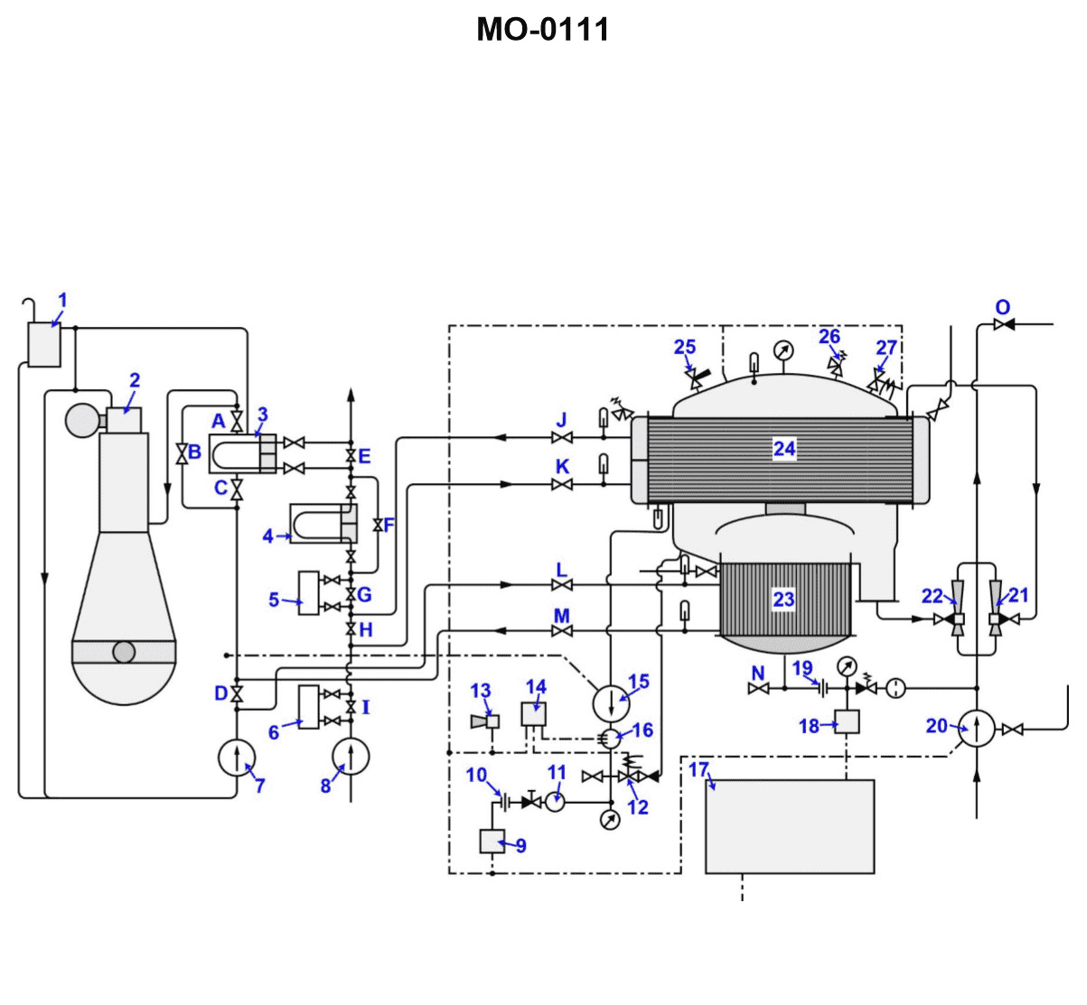
Question: If valve "D" is opened during the normal operation of the distiller shown in the illustration, which of the events listed will occur? Illustration MO-0111
A. The jacket water cooler will be overloaded, eventually causing a critical engine alarm.
B. The amount of vapor being formed in the evaporator will decrease.
C. The output of pump "7" will increase with a corresponding increase in pressure.
D. The amount of vapor formed in the evaporator will increase.
The correct answer is B) The amount of vapor being formed in the evaporator will decrease. When valve "D" is opened during normal distiller operation, it allows additional water to enter the distiller system. This extra water will dilute the concentrated brine solution in the evaporator, reducing the amount of vapor being formed. As a result, the output of the distiller will decrease. The other answer choices are incorrect because: A) Opening valve "D" will not overload the jacket water cooler or cause an engine alarm. C) The output of pump "7" will decrease, not increase, due to the reduced vapor production in the evaporator. D) The amount of vapor formed in the evaporator will decrease, not increase, when valve "D" is opened.
Question 104
Question: What would happen if valve "25" shown in the illustration, vibrated open with the unit in operation? Illustration MO-0111
A. The unit would continue to operate with no adverse effects.
B. The unit would automatically shut down due to the closing of the low-pressure contacts.
C. The absolute pressure of the unit would increase, causing a decrease in distillate output.
D. Jacket water would be automatically bypassed around the distiller.
The correct answer is C) The absolute pressure of the unit would increase, causing a decrease in distillate output. If valve "25" shown in the illustration vibrated open with the unit in operation, it would cause a loss of pressure in the system. This increased absolute pressure within the distiller would result in a decrease in the distillate output, as the higher pressure would make it more difficult for the water vapor to be expelled from the unit. The other options are incorrect because the unit would not continue to operate normally (A), there is no low-pressure shutdown mechanism described (B), and the jacket water would not be automatically bypassed (D) due to the pressure increase caused by the open valve.
Question 106
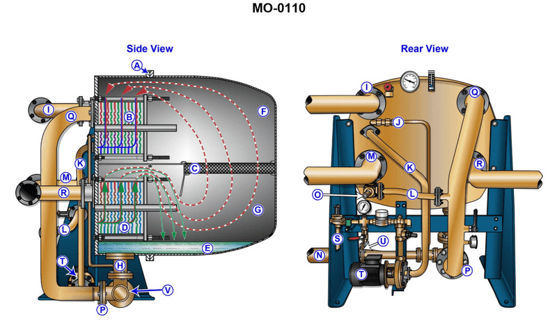
Question: What is the function of device "A" shown in the illustration? Illustration MO-0110
A. It provides a conduit for incoming feed water.
B. It aids in removing condenser tube bundles.
C. It serves as a hinge for ease of opening the shell.
D. It is only used as a lifting beam during installation.
The correct answer is C) It serves as a hinge for ease of opening the shell. The illustration MO-0110 likely depicts a device or component of a marine system, and the feature labeled as "A" is likely a hinge that allows the shell or casing to be opened for maintenance, inspection, or access to internal components. This hinge design is common in various marine equipment and systems to facilitate easy access and servicing. The other options are incorrect because they do not accurately describe the function of the feature labeled as "A" in the illustration. Option A) refers to a water feed function, Option B) describes a tube bundle removal function, and Option D) suggests it is only used during installation, which does not align with the hinge-like purpose indicated in the correct answer.
Question 107
Question: The pipe identified by the letter "J" shown in the illustration is _______________. Illustration MO-0110
A. directly connected to the feed water supply line
B. attached to the outlet of the brine ejector
C. directly connected to the jacket water supply line
D. attached to the air ejector
The correct answer is D) attached to the air ejector. The pipe identified by the letter "J" in the illustration MO-0110 is attached to the air ejector, which is used to remove air from the system. This is in accordance with the Coast Guard regulations and standard engineering practices for marine steam systems. The other answer choices are incorrect because: A) the pipe "J" is not directly connected to the feed water supply line, B) it is not attached to the outlet of the brine ejector, and C) it is not directly connected to the jacket water supply line. The pipe "J" specifically serves the air ejector, which is the correct answer based on the information provided in the illustration.
Question 108
Question: What occurs in the space labeled "G" of the device shown in the illustration? Illustration MO-0110
A. Jacket water is heated in the boiling chamber.
B. The feed water enters the device and vaporizes under vacuum conditions.
C. The feed water is cooled prior to being pumped into section "F".
D. Scale accumulates at position "E".
The correct answer is B) The feed water enters the device and vaporizes under vacuum conditions. In the illustration MO-0110, the space labeled "G" is the boiling chamber where the feed water enters and vaporizes under vacuum conditions. This is a key step in the operation of this type of steam-powered device, as the vacuum helps lower the boiling point of the water, allowing it to vaporize more efficiently. The other answer choices are incorrect because: A) refers to the jacket water rather than the feed water, C) describes cooling the feed water before it enters the device, and D) is about scale accumulation in a different part of the device.
Question 109
Question: Which of the following conditions occurs in the section labeled "F" of the device shown in the illustration? Illustration MO-0110
A. Non-condensable vapors are removed and water vapors are preheated.
B. The sea water flowing through device "I" is cooled.
C. The jacket water flowing through device "I" is heated.
D. The vapors produced in section "G" are condensed and the non-condensable gases are removed.
The correct answer is D) The vapors produced in section "G" are condensed and the non-condensable gases are removed. This is correct because in the section labeled "F" of the device shown in the illustration, the vapors produced in the previous section (G) are condensed, and the non-condensable gases are removed. This is a critical step in the overall process to ensure efficient operation and prevent the buildup of non-condensable gases, which can impair the performance of the device. The other options are incorrect because they do not accurately describe the function of section "F" as shown in the illustration. Option A refers to a different part of the device, option B describes the function of section "I," and option C describes the function of a different component.
Question 110
Question: What is the function of device "B" shown in the illustration? Illustration MO-0110
A. It serves to boil off incoming feed water.
B. It condenses the vapors formed in section "G".
C. It removes sensible heat from the jacket water.
D. It serves to cool incoming feed water.
The correct answer is B) It condenses the vapors formed in section "G". This is the correct answer because device "B" is likely a condenser, which is responsible for condensing the vapors generated in section "G" of the illustrated system. The condenser takes the hot vapors and cools them, causing them to condense back into a liquid form, which is then recirculated or discharged. The other answer choices are incorrect because they do not accurately describe the function of device "B" in the given illustration. Option A is incorrect as the boiling of feed water would likely occur upstream of the condenser. Option C is incorrect as the condenser is not responsible for removing heat from the jacket water. Option D is incorrect as the condenser does not serve to cool incoming feed water.
Question 111
Question: For the operation of the illustrated device, what fluid flow would be expected at the connection labeled "I"? Illustration MO-0110
A. Main engine jacket water.
B. The salt water feed.
C. The sea water used for condensing the water vapor.
D. The distillate discharge.
The correct answer is C) The sea water used for condensing the water vapor. This is correct because the illustration MO-0110 appears to be depicting a desalination or distillation system, where seawater is used to condense the water vapor, producing fresh water. The connection labeled "I" would therefore be the flow of seawater used for this condensation process. The other options are incorrect because they do not align with the function of the illustrated device. Main engine jacket water (A) and the distillate discharge (D) are not relevant to the seawater condensation process. The salt water feed (B) would be a separate input, not the flow at the "I" connection.
Question 112
Question: The heat exchanger plates, used in the device shown in the illustration, are produced from which of the listed materials? Illustration MO-0110
A. Titanium
B. Copper
C. Anodized aluminum
D. Phosphor bronze
The correct answer is A) Titanium. Titanium is commonly used for the heat exchanger plates in marine applications due to its corrosion resistance, high strength-to-weight ratio, and ability to withstand the harsh marine environment. The Coast Guard regulations and industry standards often specify the use of titanium or other corrosion-resistant alloys for this type of equipment to ensure durability and safety. The other options, such as copper, anodized aluminum, and phosphor bronze, would not be the optimal material choice for this application as they are more susceptible to corrosion, have lower strength-to-weight ratios, or may not meet the specific requirements for marine heat exchangers.
Question 113
Question: Which of the following is NOT a function of the water supply through item "P" shown in the illustration? Illustration MO-0110
A. It supplies feed water to evaporator.
B. It supplies the operating medium used in the removal of the brine.
C. It supplies the operating medium used in the removal of the distillate.
D. It supplies the operating medium used in the removal of air and non-condensable gases.
The correct answer is C) It supplies the operating medium used in the removal of the distillate. The water supply through item "P" in the illustration is typically used to supply feed water to the evaporator, as well as the operating medium used in the removal of the brine and air/non-condensable gases. However, it does not supply the operating medium for the removal of the distillate, as that is a separate process. The distillate is the purified water that is the end product of the evaporation process, and its removal is handled through a different mechanism. The other answer choices are incorrect because they describe functions that are accurately associated with the water supply through item "P" in the illustration.
Question 115
Question: Which of the tools listed must be used when retightening the plate type heat exchangers used in the device shown in the illustration? Illustration MO-0110
A. Torque wrench
B. Pneumatic impact wrench
C. Steel ruler or tape measure
D. Cantilever wrench
The correct answer is C) Steel ruler or tape measure. When retightening the plate type heat exchangers, a steel ruler or tape measure is required to ensure the proper tightening sequence and torque values are applied. This is necessary to maintain the proper seal and prevent leaks in the heat exchanger. The other options, such as a torque wrench (A) or pneumatic impact wrench (B), are not appropriate for this task, as they would not provide the necessary precision and control required when retightening the heat exchanger plates. A cantilever wrench (D) is used for different types of maintenance and would not be the correct tool for this specific operation.
Question 116
Question: Failure to establish sufficient vacuum when starting up the unit shown in the illustration may be the result of _______________ Illustration MO-0110
A. improper operation of the brine pump
B. neglecting to close the vent shell
C. improper operation of the distillate pump
D. neglecting to latch the dump valve
The correct answer is B) neglecting to close the vent shell. When starting up the unit shown in the illustration, it is crucial to ensure that the vent shell is properly closed. Failure to do so will prevent the establishment of sufficient vacuum, which is necessary for the unit to function correctly. Without the proper vacuum, the distillation process will be disrupted, leading to the failure to start up the unit. The other options are incorrect because they do not directly address the issue of vacuum creation. Improper operation of the brine pump (A) or distillate pump (C) may affect the overall performance of the unit, but they do not specifically impact the vacuum creation. Neglecting to latch the dump valve (D) is also not the primary cause of the failure to establish sufficient vacuum.
Question 117
Question: Which of the following conditions can cause high salinity of the distillate due to sea water leakage in the illustrated device? Illustration MO-0110
A. Improper venting during start-up.
B. Improper venting during operation.
C. Failure to properly tighten the bolts of the evaporator heat exchanger.
D. Failure to properly tighten the bolts of the condenser heat exchanger.
The correct answer is D) Failure to properly tighten the bolts of the condenser heat exchanger. If the bolts on the condenser heat exchanger are not properly tightened, it can allow seawater to leak into the distillate, resulting in high salinity. The condenser is the part of the distillation system that cools the steam back into liquid freshwater. Improper sealing here could allow seawater to contaminate the freshwater output. The other options are incorrect because they do not directly relate to seawater leakage into the distillate. Improper venting during start-up or operation (A and B) would not cause seawater contamination. Failure to tighten the evaporator heat exchanger (C) would not affect the condenser and the freshwater output.
Question 118
Question: If the demister used in the device shown in the illustration is improperly installed, which of the following will occur? Illustration MO-0110
A. The vacuum of the device will increase.
B. Interstage leakage will cause a decrease in output.
C. The temperature of the device will decrease.
D. There will be an increase of chlorides measured at the distillate pump salinity cell.
The correct answer is D) There will be an increase of chlorides measured at the distillate pump salinity cell. If the demister in the device shown in the illustration is improperly installed, it can lead to carryover of brine or salt water into the distillate stream. This increased salinity would be detected at the distillate pump salinity cell, resulting in a higher chloride measurement. The other options are incorrect because an improperly installed demister would not affect the vacuum (A), cause a decrease in output due to interstage leakage (B), or decrease the temperature (C) of the device.
Question 130
Question: Item "10" shown in the illustration is used to _______________. Illustration MO-0111
A. direct the flow from the distillate pump o
B. regulate flow from the drain pump
C. prevent damage to device "9" by reducing turbulence
D. cancel the effects of improper regulation developed by device "11"
The correct answer is A) direct the flow from the distillate pump. Item "10" is likely a valve or flow control device that is used to regulate and direct the flow of distillate (purified water) from the distillate pump. This is necessary to properly manage the flow and distribution of the distilled water produced by the system. The other answer choices are incorrect because they do not accurately describe the function of item "10" based on the information provided in the illustration and question. Option B is incorrect as it refers to regulating the drain pump, which is not the purpose of item "10". Options C and D are also incorrect as they do not accurately describe the role of item "10" in the system.
Question 131
Question: Which device is used to prevent over pressurization of the illustrated distiller? Illustration MO-0111
A. "12"
B. "13"
C. "19"
D. "26"
The correct answer is D) "26". The device used to prevent over pressurization of the illustrated distiller is a pressure relief valve, which is labeled as "26" in the diagram. Pressure relief valves are a critical safety feature on distillation systems to prevent dangerous over-pressurization that could lead to an explosion or other catastrophic failure. The other answer choices do not correspond to a pressure relief device on the diagram. Options A, B, and C refer to other components of the distillation system, such as valves, gauges, and other fittings, but not the specific pressure relief mechanism required to safely operate the distiller.
Question 132
Question: Where is the latent heat obtained to create vapor from the feed water in the illustrated distiller? Illustration MO-0111
A. During its contact period with heat exchanger "3".
B. Only as it passes through device "20".
C. From having passed through "23".
D. While it is in contact with device "24".
The correct answer is C) From having passed through "23". The latent heat required to create vapor from the feed water in the illustrated distiller is obtained as the feed water passes through device "23", which is the distillation chamber or evaporation section. In this chamber, the feed water is heated to the point of evaporation, and the latent heat required for this phase change is drawn from the heat source, such as the engine exhaust or other heat source. The other answer choices are incorrect because: A) the heat exchanger "3" is used to pre-heat the feed water, but does not provide the latent heat for evaporation; B) device "20" is likely a separator or demister, not the source of latent heat; and D) device "24" is likely a condenser, which removes latent heat from the vapor, rather than providing it.
Question 133
Question: Excess brine accumulated in the distiller, shown in the illustration, is removed during normal operation by _______________. Illustration MO-0111
A. orifice "19" regulating the amount of feed water entering the distiller, thereby preventing excess brine accumulation
B. opening the drain valve located to the left of orifice "19"
C. Sorry, that answer is not correct. The correct answer is (D) the continuous action of ejector "22"
D. the continuous action of ejector "22"
The correct answer is D) the continuous action of ejector "22". The excess brine accumulated in the distiller is removed by the continuous action of ejector "22". The ejector is responsible for maintaining the desired level of brine concentration in the distiller by continuously drawing off the excess brine. This helps prevent the accumulation of excess brine, which could negatively impact the distillation process. The other options are incorrect because they do not accurately describe the mechanism for removing excess brine. Option A focuses on the feed water regulation, which is not directly responsible for brine removal. Option B mentions a drain valve, but the question specifically states that the excess brine is removed during normal operation, not through a manual drain.
Question 134
Question: Which of the following statements describes the approximate relation between the feed water entering the unit shown in the illustration and brine being removed? Illustration MO-0111
A. Seventy-five percent of the feed water entering the unit is removed as brine.
B. Twenty-five percent of the feed water entering the device is removed as brine.
C. The amount of feed water entering the distiller is dependent upon the condition of device "7", while the amount of brine leaving is dependent upon the condition of device "21".
D. The brine will be removed at a faster rate than feed water entering to prevent the possibility of flooding.
The correct answer is A) Seventy-five percent of the feed water entering the unit is removed as brine. This is because in a typical desalination or reverse osmosis system, approximately 75% of the feed water is removed as brine or concentrated waste, while the remaining 25% is the purified freshwater product. This ratio is a common design parameter in these types of water treatment systems, as it allows for efficient operation and disposal of the concentrated brine. The other options are incorrect because B) is not the typical ratio, C) introduces irrelevant details about specific device numbers, and D) describes a scenario that would not be desirable, as removing brine at a faster rate than the feed water enters could lead to issues with the system's operation.
Question 135
Question: Which of the following statements describes what will occur to the volume of water vapor as it is exposed to the lower temperatures existing in the device labeled "24" shown in the illustration? Illustration MO-0111
A. The latent heat of condensation is removed causing the volume to increase.
B. The volume is increased as condensation occurs at the tube surfaces.
C. The volume is greatly reduced, contributing to condensation within the condenser.
D. The volume will increase if the valve labeled "J" is opened excessively, resulting in an increase of the distiller absolute pressure.
The correct answer is C) The volume is greatly reduced, contributing to condensation within the condenser. As water vapor is exposed to the lower temperatures in the device labeled "24" (which appears to be a condenser), the vapor will condense, causing the overall volume of the water vapor to be greatly reduced. This reduction in volume is a direct result of the condensation process, where the water vapor changes phase from a gas to a liquid, resulting in a much smaller volume compared to the original vapor state. The other answer options are incorrect because: A) The latent heat of condensation is actually released, not removed, during the condensation process. B) The volume decreases, not increases, as the water vapor condenses on the tube surfaces. D) The valve labeled "J" is not a relevant factor in the volume reduction due to condensation within the condenser.
Question 136
Question: What is a function of the device labeled "1" shown in the illustration? Illustration MO-0111
A. It provides a low-pressure point for combustion air filtration.
B. It relieves the excessive pressure developed in the jacket water cooler.
C. It aids in the removal of combustible gases formed in the crankcase.
D. It provides a low-pressure point for adding chemicals into the jacket water system.
The correct answer is D) It provides a low-pressure point for adding chemicals into the jacket water system. The device labeled "1" in the illustration is likely a petcock or a valve that allows for the introduction of chemicals into the jacket water system. This is a common practice to maintain the proper water chemistry and prevent corrosion or scale buildup in the engine's cooling system. The other answer choices are incorrect because they do not accurately describe the function of the device labeled "1". Option A is incorrect as it refers to air filtration, which is not the purpose of this component. Option B is incorrect as it describes the function of a pressure relief valve, which is not the same as the device shown. Option C is incorrect as it refers to the removal of crankcase gases, which is not the function of this component.
Question 161
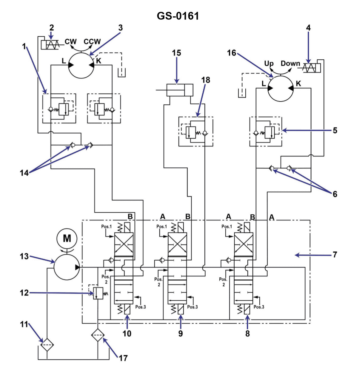
Question: You press start button on the hydraulic power unit shown in the illustration, and the motor does not start. The first thing you should check is the _______________. Illustration GS-0161
A. controller circuit breaker
B. controller contactor operating coil
C. pump discharge relief valve setting is too low
D. suction strainer condition
The correct answer is A) controller circuit breaker. If the motor does not start when the start button is pressed, the first thing to check is the controller circuit breaker, as it is responsible for providing power to the motor. The circuit breaker may have tripped due to an electrical fault or overload, preventing the motor from starting. Checking and resetting the circuit breaker is the logical first step in troubleshooting the issue. The other options are not the most likely cause of the problem. The controller contactor operating coil (B) may have an issue, but that would typically be checked after the circuit breaker. The pump discharge relief valve setting (C) and the suction strainer condition (D) are more likely to affect the motor's performance once it is running, rather than preventing it from starting in the first place.
Question 173
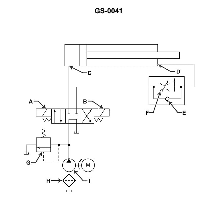
Question: Which of the following components listed is shown in the illustration? Illustration GS-0041
A. Filter
B. Variable displacement pump
C. Heat exchanger
D. All of the above
The correct answer is A) Filter. The illustration GS-0041 shows a filter component, which is a common component in various maritime systems. Filters are used to remove impurities, contaminants, or unwanted particles from fluids, such as fuel, lubricating oil, or hydraulic fluid, to ensure the proper functioning and longevity of the system. The other options, B) Variable displacement pump, C) Heat exchanger, and D) All of the above, are not depicted in the provided illustration, and therefore, they are incorrect answers.
Question 177
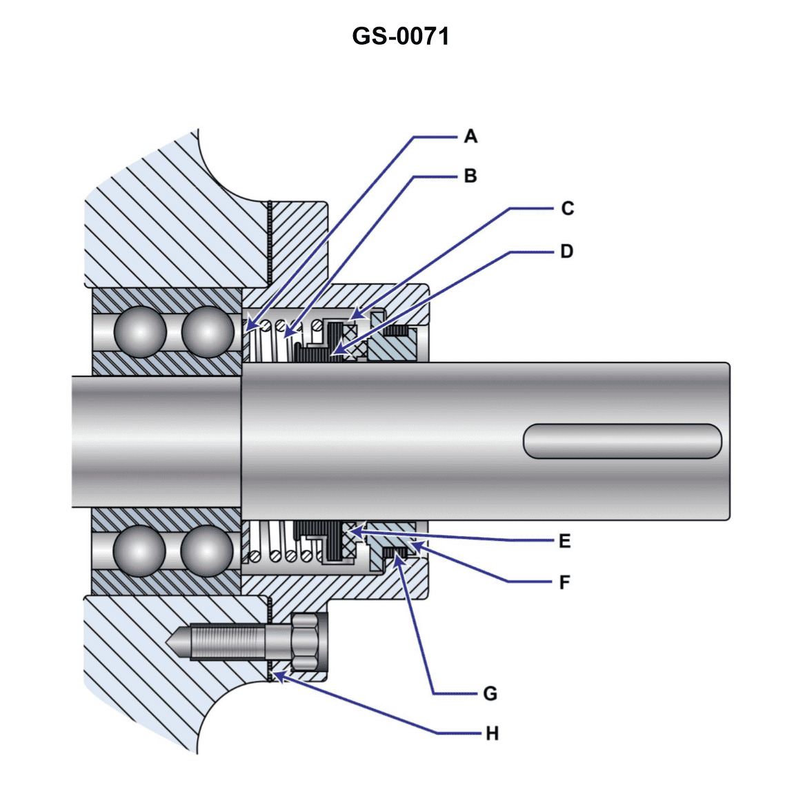
Question: The device shown in the illustration is commonly known as a/an _______________. Illustration GS-0071
A. soft-packing seal
B. quad seal
C. mechanical seal
D. spring seal
The correct answer is C) mechanical seal. A mechanical seal is a device used to prevent leakage between a rotating shaft and the housing or casing in which the shaft operates. It is commonly used in pumps, compressors, and other rotating equipment. The illustration GS-0071 likely depicts a mechanical seal, which is the appropriate choice based on the question. The other answer choices, such as a soft-packing seal, quad seal, or spring seal, are not correct in this context, as they are different types of sealing mechanisms that serve different purposes and have different designs compared to a mechanical seal.
Question 183
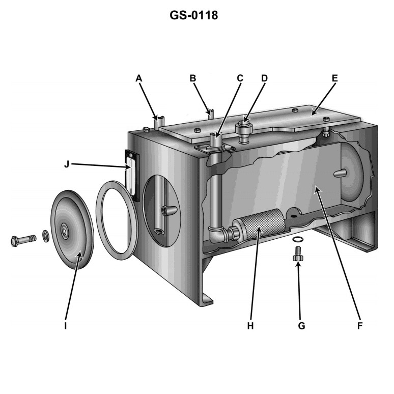
Question: In a hydraulic system using the device illustrated, the high-pressure return is provided by _______________. Illustration GS-0118
A. A
B. B
C. C
D. D
The correct answer is A. In the hydraulic system illustrated, the high-pressure return is provided by the component labeled A, which is the relief valve. The relief valve is a critical component in a hydraulic system that ensures excess pressure is diverted back to the low-pressure side of the system, preventing damage to the components. The other options (B, C, and D) are not the correct answer, as they do not represent the component responsible for the high-pressure return in the given hydraulic system.
Question 186
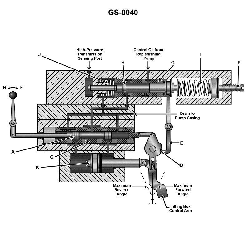
Question: A variable displacement pump is fitted with the illustrated device, the discharge flow rate will be reduced as described by which of the following statements? Illustration GS-0040
A. When part "D" rotates counter-clockwise, part "E" will rotate clockwise allowing part "G" to slide towards the set point spring “F”.
B. Part "H" will move to block the replenishing pump oil flow across part "G" as flow across hydraulic motor decreases.
C. The increase in high side pressure will gradually increase the tilting box angle of the variable displacement pump.
D. As high side pressure increases part "A", "B", and "C" will work together to re-establish the original tilting box angle.
The correct answer is B) Part "H" will move to block the replenishing pump oil flow across part "G" as flow across hydraulic motor decreases. This is correct because in a variable displacement pump, the discharge flow rate is controlled by the angle of the tilting box. As the high-side pressure increases, part "H" will move to restrict the replenishing pump oil flow across part "G", which in turn reduces the flow across the hydraulic motor, causing the discharge flow rate to decrease. The other options are incorrect because they do not accurately describe the mechanism by which the discharge flow rate is reduced in a variable displacement pump with the illustrated device. Options A, C, and D do not correctly explain how the components of the device work together to control the discharge flow rate.
Question 187
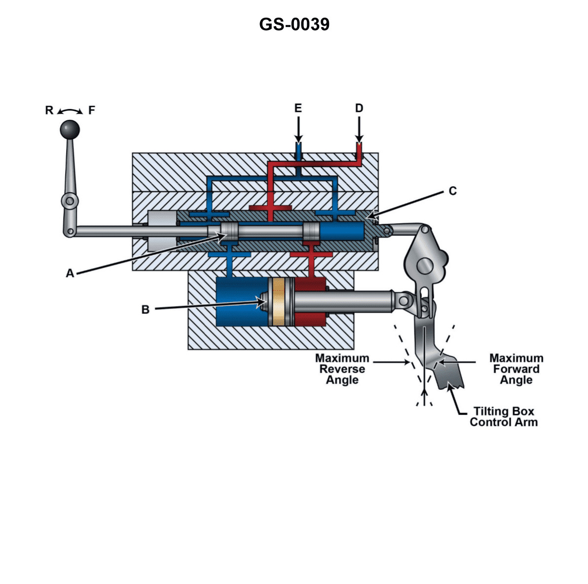
Question: If the device shown in the illustration is being used to control the output of an axial piston pump, when part "A" is moved to the right, then part "B" _______________. Illustration GS-0039
A. will move to the right, and "C" will move to the left, but lagging behind "B"
B. will move to the left, and "C" will move to the right, but will lag behind the movement of "A"
C. will move to the right, as will "C"
D. will move to the left, as will "C"
The correct answer is B. When part "A" is moved to the right, this will cause part "B" to move to the left, and part "C" will also move to the right, but will lag behind the movement of part "A". This is because the device shown is controlling the output of an axial piston pump, and the movement of the parts is directly related to the pump's operation. Specifically, as part "A" is moved to the right, it changes the angle of the pump's swash plate, which in turn causes the pump's pistons to move in the opposite direction, resulting in part "B" moving to the left and part "C" moving to the right, but lagging behind the movement of part "A". The other options are incorrect because they do not accurately describe the relationship between the movement of the different parts of the device.
Question 188
Question: Which of the following statements will be true if the position of the manual control lever, shown in the illustration, remains unchanged after the pump is placed on stroke? Illustration GS-0039
A. Although oil will leak past part 'B', the amount of pump stroke will be maintained until the control handle position is changed.
B. Although the control handle position was set, the pump displacement will fluctuate from zero to maximum flow rate until the handle is placed in its neutral position.
C. Regardless of the control handle position, the pump will gradually move to full stroke.
D. Regardless of the control handle position, the pump will gradually return to neutral stroke.
The correct answer is A) Although oil will leak past part 'B', the amount of pump stroke will be maintained until the control handle position is changed. This is correct because, in a hydraulic system, if the manual control lever position remains unchanged, the pump stroke will be maintained even if there is some internal leakage (oil leaking past part 'B'). The pump displacement will not fluctuate (as stated in option B) or gradually move to full or neutral stroke (as stated in options C and D) unless the control handle position is changed. The other options are incorrect because they do not accurately describe the behavior of the hydraulic system when the manual control lever position remains unchanged.
Question 190
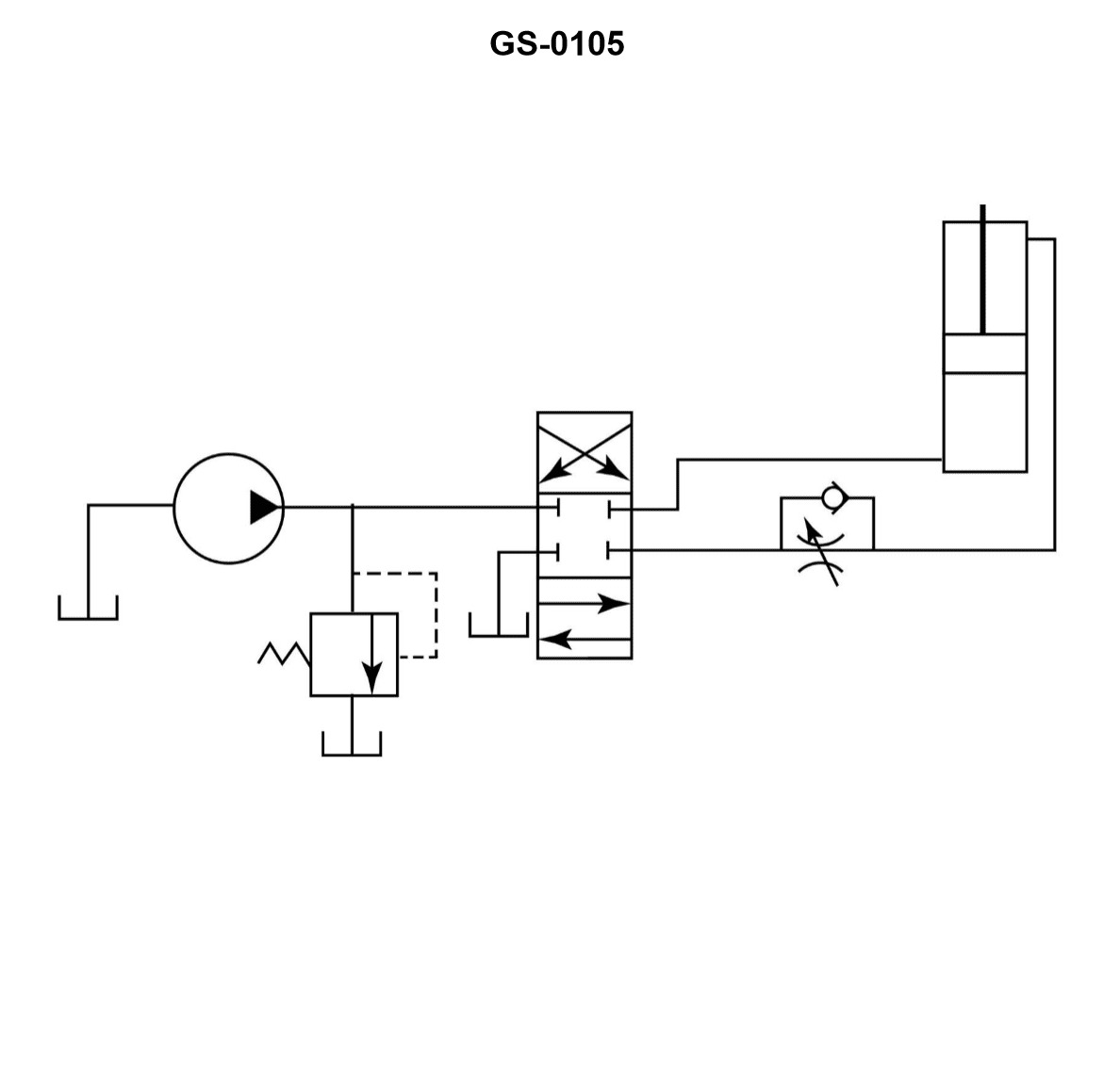
Question: Which of the statements is true concerning the illustrated hydraulic circuit when the directional control valve is centered? Illustration GS-0105
A. Oil pressure to both sides of the actuator will be equal as the pump discharge flow is directed across the relief valve.
B. A pressure differential will exist between the two ends of the actuator, with pump discharge lower than normal due to flow across the unloading valve.
C. The oil pressure will equalize at both ends of the actuator and the pump will discharge through the reducing valve to the sump.
D. The load on the actuator may cause a difference in pressure to exist between the rod and cap end, and oil discharging to the sump across the relief valve with the pump operating.
The correct answer is D. When the directional control valve is centered, the oil pressure will equalize at both ends of the actuator, but a difference in pressure may exist between the rod and cap end due to the load on the actuator. The pump will continue to discharge oil, with the excess flow being directed across the relief valve to the sump. The other options are incorrect because: A) The pressure will not be equal on both sides of the actuator when the load is unbalanced. B) The pressure differential will not be across the unloading valve, but rather the actuator itself. C) The reducing valve will not be involved in this scenario, as the pump will continue to operate and discharge to the relief valve.
Question 195
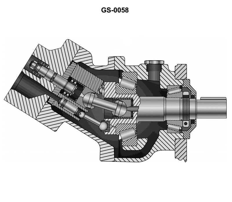
Question: If the flow rate and pressurized oil from a variable capacity pump were supplied to the device illustrated the _______________. Illustration GS-0058
A. speed would decrease, horsepower and torque would increase
B. horsepower, torque, and speed would increase proportionally
C. horsepower, torque, and speed would decrease proportionally
D. speed would increase, horsepower and torque would decrease
The correct answer is B) horsepower, torque, and speed would increase proportionally. In a variable capacity pump, an increase in the flow rate and pressurized oil supplied to a device would result in a proportional increase in the horsepower, torque, and speed of the device. This is because the higher flow rate and pressure provide more energy to the device, allowing it to generate more power and operate at a higher speed. The other answer choices are incorrect because they do not accurately describe the relationship between the pump's output and the device's performance. Decreasing speed, horsepower, and torque (option C) or increasing speed while decreasing horsepower and torque (option D) would not be the expected outcome when the pump's output is increased.
Question 196
Question: The device illustrated would be best used as a _. Illustration GS-0058
A. power take-off driven lube oil pump
B. variable capacity pump
C. hydraulic hatch supply pump
D. variable or constant speed motor
The correct answer is D) variable or constant speed motor. The device illustrated appears to be a hydraulic motor, which can be used as either a variable or constant speed motor to power various onboard systems on a vessel. This type of motor is commonly used in marine applications to provide mechanical power for tasks such as operating hatches, winches, or other equipment. The other answer choices are not as accurate. A power take-off driven lube oil pump (A) and a variable capacity pump (B) are different types of hydraulic components, not motors. A hydraulic hatch supply pump (C) is a more specific application of a hydraulic motor, but the general description of "variable or constant speed motor" is a more accurate characterization of the device shown.
Question 200
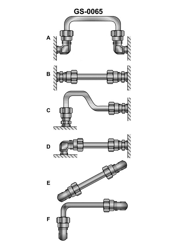
Question: The hydraulic tubing installation shown as figure "D" is INCORRECT and will probably leak when in operation because the tubing _______________. Illustration GS-0065
A. will contract in diameter and expand in length under pressure
B. will stretch and overstress the male threads on the fitting
C. and its fittings cannot be properly installed and tightened
D. cannot flex at right angles to the pressure applied by the fluid because it is not properly twisted
The correct answer is C) the tubing and its fittings cannot be properly installed and tightened. The proper installation and tightening of hydraulic tubing and fittings is crucial to prevent leaks and ensure safe operation. If the tubing and fittings are not installed correctly, they cannot be properly tightened, which can lead to leaks when the system is under pressure. This is the main reason why the hydraulic tubing installation shown in figure "D" is incorrect and will likely leak. The other options are incorrect because they do not directly address the issue of improper installation and tightening. Option A describes potential tubing behavior under pressure, but does not explain why the installation is incorrect. Option B relates to overstressing the fittings, but does not explain the root cause. Option D discusses the ability to flex at right angles, but this is not the primary reason for the potential leak.
Question 202
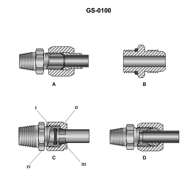
Question: Of the hydraulic tubing fittings illustrated, the flared fitting for high-pressure use is represented by figure _______________. Illustration GS-0100
A. A or C
B. A or B
C. B or C
D. C or D
The correct answer is B) A or B. The flared fitting for high-pressure use is represented by figure A or B in the illustration GS-0100. Flared fittings are commonly used for high-pressure hydraulic systems because they create a tight, leak-proof seal by deforming the tubing into the fitting. This type of fitting is preferred over other options like threaded fittings for high-pressure applications. The other answer choices are incorrect because figure C represents a compression fitting, which is not suitable for high-pressure hydraulic systems, and figure D represents a straight coupling, which is a lower-pressure fitting not intended for high-pressure use.
Question 210
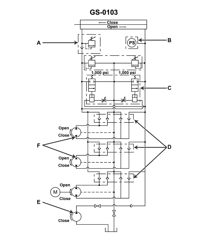
Question: Item "B" shown in the illustrated hydraulic circuit is used to _______________. Illustration GS-0103
A. act as a power source to operate the pump indicated as "E"
B. shut down the operation of pump "E" when the watertight door has closed
C. act as a power source to operate the pumps indicated as "F"
D. shut down the remotely operated electric motor driven pump when the watertight door has closed
The correct answer is D) shut down the remotely operated electric motor driven pump when the watertight door has closed. This is correct because item "B" in the hydraulic circuit is likely a solenoid valve or other control device that is designed to automatically shut off the remotely operated electric motor driven pump (indicated as "E") when a watertight door has closed. This feature is important for ensuring the safe operation of the system by preventing the pump from continuing to run after the watertight door has sealed, which could lead to system damage or other safety issues. The other answer choices are incorrect because they do not accurately describe the purpose of item "B" in the illustrated hydraulic circuit. Option A is incorrect because item "B" is not a power source for the pump. Option B is incorrect because item "B" is not used to shut down the pump operation, but rather to shut down the pump when the watertight door has closed. Option C is incorrect because item "B" is not a power source for the other pumps indicated as "F".
Question 211
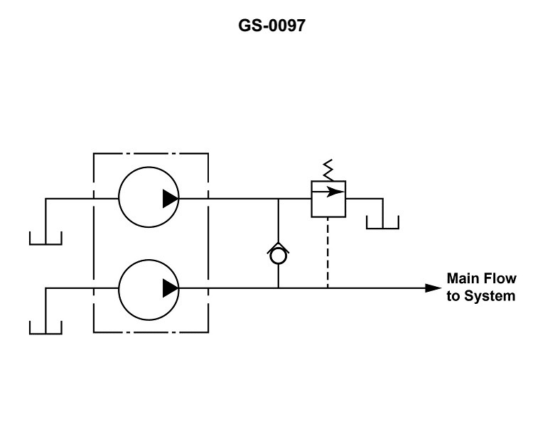
Question: The illustrated hydraulic pump graphic symbol is used to depict a/an _______________. Illustration GS-0097
A. combined pump unit
B. series-flow pump unit
C. double pump unit
D. two-stage pump unit
The correct answer is C) double pump unit. The illustrated hydraulic pump graphic symbol GS-0097 depicts a double pump unit, which is a hydraulic component that has two separate pumping elements within a single housing. This configuration allows for simultaneous operation of two independent pumping functions, providing increased hydraulic power and redundancy compared to a single pump unit. The other answer choices are incorrect because: A) a combined pump unit refers to a single pump that can perform multiple functions, B) a series-flow pump unit has the pumping elements arranged in a sequential flow path, and D) a two-stage pump unit has a single pumping element with two distinct pressure stages.
Question 212
Question: Item "E" shown in the illustration is used in the hydraulic circuit as _______________. Illustration GS-0103
A. one of two motor driven remotely operated pumps to open and close the watertight door
B. the manually operated pump located in a common passage way to close the watertight door in an emergency
C. the manually operated pump used to open or close the watertight door from the engine room side
D. motor driven pump used to close the watertight door from the navigation bridge in an emergency
The correct answer is B) the manually operated pump located in a common passageway to close the watertight door in an emergency. This is the correct answer because watertight doors on vessels are typically equipped with both remotely operated and manual mechanisms to ensure the doors can be closed in an emergency, even if the primary power source fails. The manually operated pump located in a common passageway allows crew to close the door locally and independently of any automated systems. The other options are incorrect because they do not accurately describe the function of the manually operated pump shown as item "E" in the illustration. Options A, C, and D all refer to other types of pumps or controls used to operate the watertight door, but do not match the description of the manual emergency pump in the passageway.
Question 213
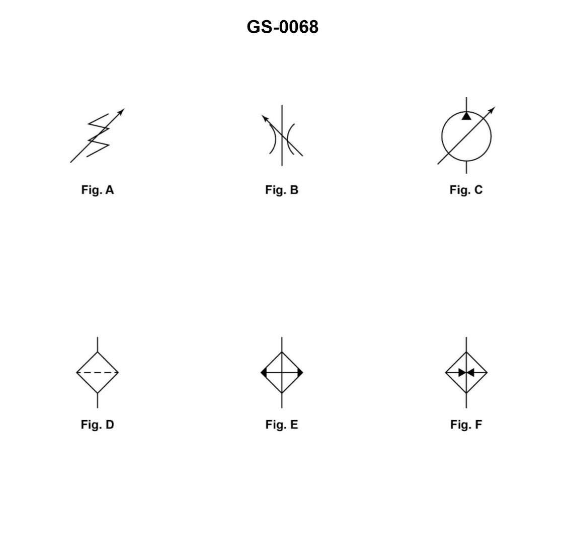
Question: An arrow superimposed on a hydraulic graphic symbol at approximately 45°, as shown in the illustrated figures A, B, and C, indicates the component _______________. Illustration GS-0068
A. is pilot controlled
B. allows flow in one direction only
C. is pressure compensated
D. can be adjusted or varied
The correct answer is D) can be adjusted or varied. The arrow superimposed on a hydraulic graphic symbol at approximately 45° indicates that the component can be adjusted or varied. This is because the 45° angled arrow is a standard symbol used in hydraulic diagrams to represent an adjustable or variable component, such as a flow control valve or a pressure relief valve. The other answer choices are incorrect because they do not accurately represent the meaning of the 45° angled arrow symbol. A) is incorrect because the arrow does not indicate pilot control. B) is incorrect because the arrow does not indicate one-way flow. C) is incorrect because the arrow does not indicate pressure compensation.
Question 226
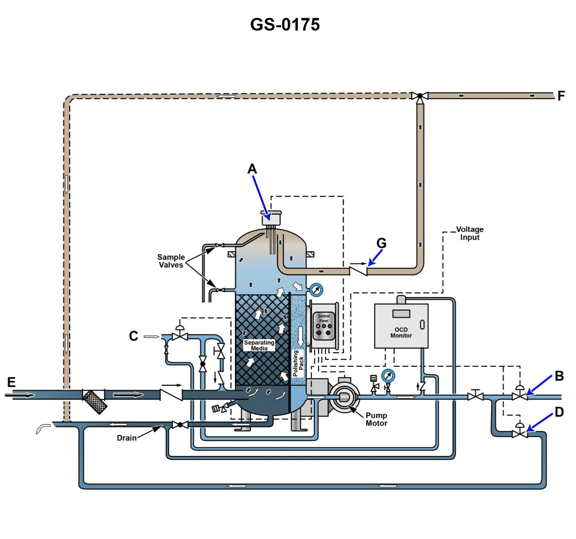
Question: Referring to the illustration, what would be the result if the lower oil/water interface detection probe became faulty? Illustration GS-0175
A. The unit would not be able to transition from ending the oil discharge mode to initiating the separation processing mode.
B. The unit would not be able to transition from the overboard discharge mode to the recirculation mode while in the separation processing mode.
C. The unit would not be able to transition from ending the separation processing mode to initiating the oil discharge mode.
D. The unit would not be able to come out of the oily-water separator idle mode and begin processing bilge water.
The correct answer is C) The unit would not be able to transition from ending the separation processing mode to initiating the oil discharge mode. This is because the lower oil/water interface detection probe is used to determine when the oil layer has been sufficiently separated from the water, allowing the system to transition from the separation processing mode to the oil discharge mode. If this probe is faulty, the system would not be able to reliably detect when the separation is complete, preventing it from moving to the oil discharge phase. The other answer choices are incorrect because they do not directly relate to the function of the lower oil/water interface detection probe. The probe's primary role is to signal the transition between separation processing and oil discharge, not the other modes mentioned in the other answer choices.
Question 227
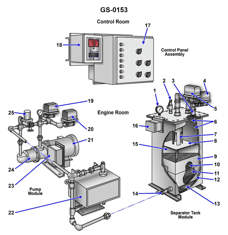
Question: If item "1" shown in the illustration is a compound gage indicating zero psig and the water level in the bilges is one foot high, the unit is _______________. Illustration GS-0153
A. in the oil discharge mode
B. processing the bilge water
C. damaged and should not be used
D. not turned on
The correct answer is D) not turned on. If the compound gauge is indicating zero psig (pounds per square inch gauge) and the water level in the bilges is 1 foot high, this suggests that the gauge is not turned on or functioning properly. A properly functioning gauge should indicate the actual pressure in the system, not zero. The fact that the water level is 1 foot high also suggests the gauge is not properly monitoring the system. Therefore, the correct answer is that the gauge is not turned on and should not be used in this condition. The other answer choices are incorrect because they do not accurately describe the situation based on the information provided. The gauge is not in an oil discharge mode, not processing bilge water, and is not necessarily damaged - it simply appears to not be functioning properly.
Question 228
Question: Referring to the illustration, what would be the result if the upper oil/water interface detection probe became faulty? Illustration GS-0175
A. The unit would not be able to transition from ending the oil discharge mode to initiating the separation processing mode.
B. The unit would not be able to come out of the oily-water separator idle mode and begin processing bilge water.
C. The unit would not be able to transition from the overboard discharge mode to the recirculation mode while in the separation processing mode.
D. The unit would not be able to transition from ending the separation processing mode to initiating the oil discharge mode.
The correct answer is A) The unit would not be able to transition from ending the oil discharge mode to initiating the separation processing mode. This is because the upper oil/water interface detection probe is used to determine when the oil layer has been sufficiently discharged and the unit can then transition to the separation processing mode to filter the remaining bilge water. If this probe is faulty, the unit would not be able to properly detect the transition point between the oil and water layers, preventing it from moving from the oil discharge mode to the separation processing mode. The other answer choices are incorrect because they do not directly relate to the function of the upper oil/water interface detection probe in transitioning between the oil discharge and separation processing modes.
Question 237
Question: Referring to the illustration, note that the solenoid in line "C" is closed. The check valve in line "E" is open. The separator service pump is running. The check valve in line "G" is closed. Valve "B" is open. Valve "D" is closed. What is the operational status of the oily-water separator unit? Illustration GS-0175
A. The oily-water separator is in the bilge water separation processing mode with water discharging back to the bilge water holding tank with an oil content less than 15 ppm.
B. The oily-water separator is in the bilge water separation processing mode with water discharging back to the bilge water holding tank with an oil content greater than 15 ppm.
C. The oily-water separator is in the bilge water separation processing mode with water discharging overboard with an oil content greater than 15 ppm.
D. The oily-water separator is in the bilge water separation processing mode with water discharging overboard with an oil content less than 15 ppm.
The correct answer is D) The oily-water separator is in the bilge water separation processing mode with water discharging overboard with an oil content less than 15 ppm. With the solenoid in line "C" closed, the check valve in line "E" open, and the separator service pump running, the oily-water separator is actively processing bilge water. Since the check valve in line "G" is closed and valve "D" is closed, the processed water is being discharged overboard, not back to the bilge water holding tank. With these conditions, the oil content of the discharged water must be less than 15 ppm to comply with international regulations for overboard discharge. The other options are incorrect because they either indicate the oil content is greater than 15 ppm or the water is being discharged back to the bilge water holding tank, which is not the case based on the given information.
Question 238
Question: The line labeled "G", as shown in the illustration would be identified as the _______________. Illustration GS-0175
A. waste oil outlet line
B. processed water outlet line
C. clean water inlet line
D. oily bilge water inlet line
The correct answer is A) waste oil outlet line. The illustration GS-0175 likely depicts a typical oil/water separator system found on many marine vessels. The line labeled "G" would be the waste oil outlet line, which carries the concentrated oil from the separator to a waste oil storage tank or overboard discharge. The other answer choices are incorrect because: B) is the line for the processed (cleaned) water exiting the separator, C) is the clean water inlet line feeding the separator, and D) is the oily bilge water inlet line entering the separator.
Question 239
Question: What is the normal direction of flow through the device shown in the illustration while operating in the processing mode? Illustration GS-0153
A. The oily-water mixture enters through the pressure control valve "2" and exits with the processed liquid through valve "14".
B. The oily-water mixture enters through valve "4" and exits as processed liquid through valve "14".
C. The oily-water mixture enters through valve "5" and exits the separator through valve "14" as processed liquid.
D. The oily-water mixture enters through valve "14" and exits with the processed liquid through valve "4".
The correct answer is C. The oily-water mixture enters through valve "5" and exits the separator through valve "14" as processed liquid. This is the correct answer because the normal direction of flow through the device in the processing mode is from the inlet valve (valve "5") to the outlet valve (valve "14"). The oily-water mixture is fed into the separator through valve "5" and the processed liquid, with the oil removed, exits through valve "14". The other answer choices are incorrect because they do not accurately depict the normal direction of flow through the device. Options A, B, and D describe flow patterns that do not match the typical configuration and operation of this type of oily-water separator.
Question 240
Question: The component labeled "A" as shown in the illustration would be identified as the . Illustration GS-0175
A. oil content monitor probe
B. separator vessel pressure relief valve
C. oil/water interface level sensing probe
D. separator vessel vacuum breaker
The correct answer is C) oil/water interface level sensing probe. The oil/water interface level sensing probe is used to detect the level of the interface between the oil and water layers in a separator vessel. This is a critical component for ensuring proper operation and preventing oil from being discharged overboard. The other options are not the correct identification for the component labeled "A" in the illustration. The oil content monitor probe (A) measures the oil content of the effluent, the separator vessel pressure relief valve (B) is a safety device, and the separator vessel vacuum breaker (D) is used to prevent implosion of the vessel. None of these match the description of the component labeled "A" in the illustration.
Question 241
Question: The line labeled "E", as shown in the illustration, would be identified as the _______________. Illustration GS-0175
A. processed water outlet line
B. clean water inlet line
C. waste oil outlet line
D. oily bilge water inlet line
The correct answer is D) oily bilge water inlet line. The line labeled "E" in the illustration GS-0175 would be identified as the oily bilge water inlet line. This is because the oily bilge water, which is contaminated with oil and other waste, needs to be properly disposed of and the inlet line connects to the system that handles this waste. The other answer choices are incorrect because they do not match the function and purpose of the line labeled "E" in the provided illustration. The processed water outlet line, clean water inlet line, and waste oil outlet line would have different identifications and serve different purposes in the system.
Question 242
Question: Referring to the illustration, note that the solenoid in line "C" is closed. The check valve in line "E" is open. The separator service pump is running. The check valve in line "G" is closed. Valve "B" is closed. Valve "D" is open. What is the operational status of the oily-water separator unit? Illustration GS-0175
A. The oily-water separator is in the bilge water separation processing mode with water discharging back to the bilge water holding tank with an oil content greater than 15 ppm.
B. The oily-water separator is in the bilge water separation processing mode with water discharging back to the bilge water holding tank with an oil content less than 15 ppm.
C. The oily-water separator is in the bilge water separation processing mode with water discharging overboard with an oil content less than 15 ppm.
D. The oily-water separator is in the bilge water separation processing mode with water discharging overboard with an oil content greater than 15 ppm.
The correct answer is A) The oily-water separator is in the bilge water separation processing mode with water discharging back to the bilge water holding tank with an oil content greater than 15 ppm. This is correct because with the solenoid in line C closed, the check valve in line E open, and the separator service pump running, the oily-water separator is actively processing bilge water. However, since the check valve in line G is closed and valve D is open, the processed water is being discharged back to the bilge water holding tank rather than overboard. Additionally, with valve B closed, the system is not discharging the processed water overboard, indicating the oil content is likely greater than 15 ppm, the maximum allowable limit for overboard discharge. The other options are incorrect because they do not accurately reflect the operational status of the oily-water separator based on the given information.
Question 243
Question: The components indicated as "7" and "8" as shown in the illustration, are known as the _______________. Illustration GS-0153
A. first stage oil separator and drip pan
B. inlet weir and inlet baffle
C. second stage oil separator and drip pan
D. outlet weir and outlet baffle
The correct answer is B) inlet weir and inlet baffle. The components labeled as "7" and "8" in the illustration GS-0153 represent the inlet weir and inlet baffle, respectively. The inlet weir is a barrier that helps to control the flow of liquid into the separator, while the inlet baffle is a device that helps to distribute the incoming flow and reduce turbulence, allowing for more efficient separation of oil and water. The other answer choices are incorrect because they do not accurately describe the components labeled as "7" and "8" in the given illustration. Option A refers to a first-stage oil separator and drip pan, option C refers to a second-stage oil separator and drip pan, and option D refers to an outlet weir and outlet baffle, which are not the components shown in the illustration.
Question 244
Question: The function of item "7" shown in the illustration is to_______________. Illustration GS-0153
A. direct the flow of the oily-water mixture against the coalescer bed
B. support the tank access panel
C. allow the oil accumulated to exit the device, while remaining separated from the liquid
D. prevent separated oil from mixing with the incoming bilge water
The correct answer is D) prevent separated oil from mixing with the incoming bilge water. The function of item "7" in the illustration GS-0153 is to act as a weir or baffle that prevents the separated oil from re-mixing with the incoming bilge water. This helps maintain the oil/water separation within the device and ensures that the oil can be properly discharged or disposed of separately. The other answer choices are incorrect because: A) does not describe the function of item 7, B) refers to a different component, and C) does not fully capture the purpose of preventing re-mixing of the oil and water.
Question 245
Question: The line labeled "C", as shown in the illustration would be identified as the _______________. Illustration GS-0175
A. processed water outlet line
B. clean water inlet line
C. oily bilge water inlet line
D. waste oil discharge line
The correct answer is B) clean water inlet line. The illustration GS-0175 likely depicts a schematic diagram of a marine oily water separator system, which is a common piece of equipment found on commercial vessels. The line labeled "C" would be the clean water inlet line, which carries the treated water from the separator back into the vessel's system for reuse or overboard discharge. The other answer choices are incorrect because: A) The processed water outlet line would not be labeled "C". C) The oily bilge water inlet line would typically be labeled with a different letter. D) The waste oil discharge line would also have a different label.
Question 246
Question: When the oily-water separator, shown in the illustration, is in operation and processing clear bilge water, what should be the internal water level? Illustration GS-0153
A. The water level in the tank should be slightly above the upper coalescer bed "9".
B. The water level should be located in the lower section of the tank as controlled by flow control valve "14".
C. The water level should be located in the upper section of the tank.
D. No water level is maintained in the tank.
The correct answer is C) The water level should be located in the upper section of the tank. When the oily-water separator is in operation and processing clear bilge water, the internal water level should be maintained in the upper section of the tank. This allows the water to flow through the coalescer bed (item 9) and the oil/water interface to remain in the upper portion, facilitating the separation of oil from the water. The water level is not controlled by the flow control valve (item 14), which is used to regulate the flow rate, not the water level. There is no need to maintain the water level slightly above the coalescer bed, and the tank should not be operated without any water level.
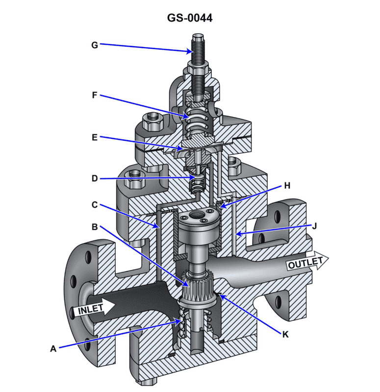
Question 247
Question: How would the pressure setting of the illustrated self-contained, internal-pilot, piston- operated steam pressure-reducer be raised to a higher set point? Illustration GS-0044
A. The adjusting spring would need to have its compression load reduced by rotating the adjusting screw counter-clockwise further out of the adjusting spring chamber.
B. The adjusting spring would need to have its compression load increased by rotating the adjusting screw clockwise further into the adjusting spring chamber.
C. The adjusting spring would need to have its compression load reduced by rotating the adjusting screw clockwise further into the adjusting spring chamber.
D. The adjusting spring would need to have its compression load increased by rotating the adjusting screw counter-clockwise further out of the adjusting spring chamber.
The correct answer is B) The adjusting spring would need to have its compression load increased by rotating the adjusting screw clockwise further into the adjusting spring chamber. To raise the pressure setting of the illustrated self-contained, internal-pilot, piston-operated steam pressure-reducer, the compression load of the adjusting spring must be increased. This is achieved by rotating the adjusting screw clockwise, which pushes the screw further into the adjusting spring chamber and increases the spring's compression. This increased spring compression then raises the set point of the pressure-reducer. The other options are incorrect because reducing the spring compression (A and C) or increasing it by rotating the screw counter-clockwise (D) would lower the pressure setting, which is the opposite of the desired outcome.
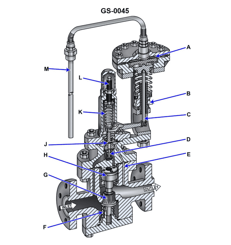
Question 248
Question: How would the illustrated valve respond to a complete loss of charge from the remote bulb-to-control diaphragm power element if the valve is used as a temperature control valve for a steam-heated heavy fuel oil service heater? Illustration GS-0045
A. The valve would fail in the fully closed position, resulting in a low fuel oil temperature alarm.
B. The valve would fail in the fully open position, resulting in a high fuel oil temperature alarm.
C. It is not possible to predict how the valve will respond to a complete loss of charge from the power element.
D. The valve would fail in the exact position it was in before the power element lost its complete charge, resulting in a fluctuation in fuel oil temperature as demand changes.
The correct answer is B) The valve would fail in the fully open position, resulting in a high fuel oil temperature alarm. This is because when a pneumatic temperature control valve with a remote bulb-to-control diaphragm power element loses its charge, the valve will fail in the fully open position. This is due to the design of the valve, which uses the pneumatic pressure from the power element to close the valve against the force of the spring. When the power element loses its charge, the spring force takes over, causing the valve to fail open and allow maximum flow, resulting in a high fuel oil temperature. The other options are incorrect because A) the valve would not fail closed, C) it is possible to predict the failure mode, and D) the valve would not remain in its previous position.
Question 249
Question: In the illustrated self-contained, internal-pilot, piston-operated steam pressure- reducing valve, what statement is true concerning the pilot and main valves? Illustration GS-0044
A. The pilot valve is upward seating and the main valve is downward seating.
B. The pilot valve is downward seating and the main valve is upward seating.
C. The pilot valve is downward seating and the main valve is downward seating.
D. The pilot valve is upward seating and the main valve is upward seating.
The correct answer is D) The pilot valve is upward seating and the main valve is upward seating. This is correct because in a self-contained, internal-pilot, piston-operated steam pressure-reducing valve, the pilot valve and the main valve are typically designed with upward seating configurations. This allows the valves to close against the pressure of the steam, ensuring a tight seal and effective pressure reduction. The other options are incorrect because they do not accurately describe the seating configuration of the pilot and main valves in this type of pressure-reducing valve system.
Question 250
Question: Suppose the illustrated self-contained, internal-pilot, piston-operated temperature control valve is part of the temperature control system for a steam-heated heavy fuel oil service heater for a steam boiler. If there was a decrease in demand for fuel by the boiler, what statement correctly represents how the valve would initially respond? Illustration GS-0045
A. The fuel oil heater fuel outlet temperature would decrease, causing the remote bulb pressure to decrease and the control diaphragm to flex upward and through lever action, further open the pilot valve.
B. The fuel oil heater fuel outlet temperature would increase, causing the remote bulb pressure to increase and the control diaphragm to flex upward and through lever action, further open the pilot valve.
C. The fuel oil heater fuel outlet temperature would decrease, causing the remote bulb pressure to decrease and the control diaphragm to flex downward and through lever action, further close the pilot valve.
D. The fuel oil heater fuel outlet temperature would increase, causing the remote bulb pressure to increase and the control diaphragm to flex downward and through lever action, further close the pilot valve.
The correct answer is D. If there is a decrease in demand for fuel by the boiler, the fuel oil heater fuel outlet temperature would increase. This increase in temperature would cause the remote bulb pressure to increase, and the control diaphragm would flex downward. Through lever action, this would further close the pilot valve, reducing the flow of fuel to the heater and maintaining the desired temperature. The other options are incorrect because they do not correctly describe the response of the valve to a decrease in fuel demand. Specifically, options A and B describe the valve opening further, which would be the opposite of the correct response, and option C describes the diaphragm flexing downward, which is also incorrect.
Question 251
Question: Suppose the illustrated self-contained, internal-pilot, piston-operated temperature control valve is part of the temperature control system for a steam-heated heavy fuel oil service heater for a steam boiler. If there was an increase in demand for fuel by the boiler, what statement correctly represents how the valve would initially respond? Illustration GS-0045
A. The fuel oil heater fuel outlet temperature would increase, causing the remote bulb pressure to increase and the control diaphragm to flex downward and through lever action, further close the pilot valve.
B. The fuel oil heater fuel outlet temperature would decrease, causing the remote bulb pressure to decrease and the control diaphragm to flex upward and through lever action, further open the pilot valve.
C. The fuel oil heater fuel outlet temperature would decrease, causing the remote bulb pressure to decrease and the control diaphragm to flex downward and through lever action, further close the pilot valve.
D. The fuel oil heater fuel outlet temperature would increase, causing the remote bulb pressure to increase and the control diaphragm to flex upward and through lever action, further open the pilot valve.
The correct answer is B. If there is an increase in demand for fuel by the boiler, the fuel oil heater fuel outlet temperature would decrease, causing the remote bulb pressure to decrease. This would make the control diaphragm flex upward, and through lever action, further open the pilot valve. This allows more heated fuel oil to flow to the boiler, increasing the fuel oil heater fuel outlet temperature back to the desired setpoint. The other options are incorrect because they do not accurately describe how the temperature control valve would initially respond to an increase in fuel demand by the boiler. Options A and D describe the opposite response, where the valve would close instead of open. Option C describes the valve closing instead of opening in response to a decrease in fuel oil heater fuel outlet temperature.
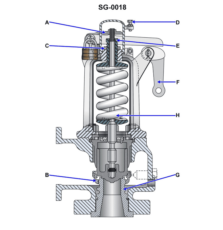
Question 255
Question: Referring to the illustrated huddling-chamber safety valve, what statement is true concerning the adjustment of the popping pressure? Illustration SG-0018
A. Popping pressure is adjusted by rotating the release nut
B. .
C. Popping pressure is adjusted by rotating the adjusting ring
D. .
The correct answer is C) Popping pressure is adjusted by rotating the adjusting ring. The popping pressure of a safety valve is the pressure at which the valve will open and release pressure. For the illustrated huddling-chamber safety valve, the popping pressure is adjusted by rotating the adjusting ring, not the release nut. Turning the adjusting ring clockwise increases the popping pressure, while turning it counterclockwise decreases the popping pressure. The other answer options are incorrect because the release nut is not used to adjust the popping pressure on this type of safety valve. The release nut is used for other functions, such as manually opening the valve, but does not affect the pressure setting.
Question 257
Question: Referring to the illustrated huddling-chamber safety valve, what statement is true concerning the adjustment of blow down? Illustration SG-0018
A. Blow down is adjusted by rotating the release nut
B. .
C. Blow down is adjusted by rotating the adjusting ring
D. .
The correct answer is C) Blow down is adjusted by rotating the adjusting ring. The blow down on the illustrated huddling-chamber safety valve is adjusted by rotating the adjusting ring, not the release nut. This allows the operator to fine-tune the pressure at which the valve will open and release pressure, which is an important safety feature for the proper operation of the valve. The other answer choices are incorrect because the release nut is not used to adjust the blow down, and the question does not provide enough information to determine what the other options might refer to.
Question 259
Question: In the illustrated huddling-chamber safety valve, what statement is true concerning the opening and closing forces acting upon the disc? Illustration SG-0018
A. The spring force acting upward on the disc is a valve opening force, and the sensed pressure acting downward on the disc is a valve closing force.
B. The spring force acting upward on the disc is a valve closing force, and the sensed pressure acting downward on the disc is a valve opening force.
C. The spring force acting downward on the disc is a valve opening force, and the sensed pressure acting upward on the disc is a valve closing force.
D. The spring force acting downward on the disc is a valve closing force, and the sensed pressure acting upward on the disc is a valve opening force.
The correct answer is C. The spring force acting downward on the disc is a valve opening force, and the sensed pressure acting upward on the disc is a valve closing force. This is because the spring force works to push the disc open, while the sensed pressure works to push the disc closed, in order to maintain the desired pressure in the huddling-chamber safety valve. The other options are incorrect because they describe the forces in the opposite way. The spring force should act to open the valve, not close it, and the sensed pressure should act to close the valve, not open it.
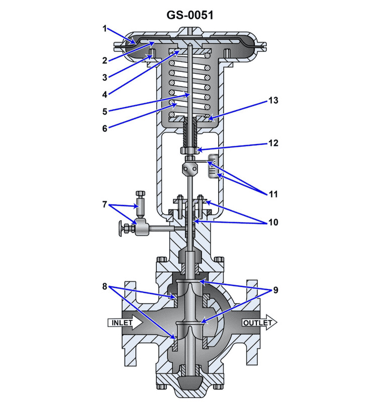
Question 260
Question: Referring to the illustrated pneumatically operated diaphragm actuated control valve, what statement is true? Illustration GS-0051
A. The control valve has a single disc which is upward seating.
B. The control valve has a single disc which is downward seating.
C. The control valve has two discs which are both upward seating.
D. The control valve has two discs which are both downward seating.
The correct answer is D. The control valve has two discs which are both downward seating. The reason this is correct is that in a pneumatically operated diaphragm actuated control valve, the valve discs are designed to be downward seating. This configuration allows the valve to fail in the closed position when the pneumatic supply is lost, which is a common safety feature for this type of valve. The two discs ensure a tight seal when the valve is closed. The other options are incorrect because a single disc valve would not provide the redundancy and fail-safe behavior required for this type of critical control valve. Additionally, upward seating valves are less common in this application and would not provide the desired fail-closed functionality.
Question 261
Question: Suppose the illustrated pneumatically operated diaphragm actuated control valve is used to control the fuel oil outlet temperature of a steam-heated heavy fuel oil heater by controlling the steam flow. What would be the result if the stem packing was over-tightened and the stem was unable to vertically move in either direction? Illustration GS-0051
A. The valve would fail in the fully closed position, most likely resulting in a low fuel oil temperature alarm condition.
B. The valve will lose control of the fuel oil temperature with the result that the fuel temperature will fluctuate with changes in fuel demand.
C. The valve would fail in the fully open position, most likely resulting in a high fuel oil temperature alarm condition.
D. It is not possible to predict how the valve would respond to over-tightened valve stem packing.
The correct answer is B) The valve will lose control of the fuel oil temperature with the result that the fuel temperature will fluctuate with changes in fuel demand. Explanation: If the stem packing is over-tightened, the stem will be unable to move vertically in either direction. This means the valve will not be able to respond to changes in the fuel oil temperature and modulate the steam flow accordingly. As a result, the valve will lose control of the fuel oil temperature, causing it to fluctuate with changes in fuel demand, rather than maintaining a stable temperature. The other options are incorrect because: A) the valve would not fail in the fully closed position, C) the valve would not fail in the fully open position, and D) it is possible to predict the valve's response to over-tightened packing, as explained above.
Question 263
Question: Assuming that the flow is from left to right on the illustrated pneumatically operated diaphragm actuated control valve, what statement is true? Illustration GS-0051
A. Inlet pressure acts on the upper surface of the top disc and the lower surface of the bottom disc for the purpose of achieving hydraulic balance so that inlet pressure does not influence the valve position.
B. Inlet pressure acts on the lower surface of the top disc and the upper surface of the bottom disc for the purpose of achieving hydraulic balance so that inlet pressure does not influence the valve position.
C. Inlet pressure acts on the upper surface of the top disc and the upper surface of the bottom disc for the purpose of achieving a hydraulic assist to aid in valve closing.
D. Inlet pressure acts on the lower surface of the top disc and the lower surface of the bottom disc for the purpose of achieving a hydraulic assist to aid in valve opening.
The correct answer is B) Inlet pressure acts on the lower surface of the top disc and the upper surface of the bottom disc for the purpose of achieving hydraulic balance so that inlet pressure does not influence the valve position. This is correct because in a pneumatically operated diaphragm actuated control valve, the inlet pressure is designed to act on the opposing surfaces of the top and bottom discs. This creates a hydraulic balance, ensuring that the inlet pressure does not impact the positioning of the valve. The other answer choices do not accurately describe the inlet pressure acting on the disc surfaces to achieve this hydraulic balance.
Question 264
Question: In the illustrated pneumatically operated, diaphragm actuated control valve, what statement is true concerning the opening and closing forces acting upon the control diaphragm? Illustration GS-0051
A. The spring force acting on the control diaphragm is a valve opening force, and the pilot pressure acting on the bottom of the control diaphragm is a valve closing force.
B. The spring force acting on the control diaphragm is a valve closing force, and the pilot pressure acting on the top of the control diaphragm is a valve opening force.
C. The spring force acting on the control diaphragm is a valve opening force, and the pilot pressure acting on the top of the control diaphragm is a valve closing force.
D. The spring force acting on the control diaphragm is a valve closing force, and the pilot pressure acting on the bottom of the control diaphragm is a valve opening force.
The correct answer is C) The spring force acting on the control diaphragm is a valve opening force, and the pilot pressure acting on the top of the control diaphragm is a valve closing force. This is correct because in a pneumatically operated, diaphragm actuated control valve, the spring force acts to open the valve, while the pilot pressure acting on the top of the control diaphragm applies a closing force. The spring provides the opening force, while the pilot pressure above the diaphragm pushes the diaphragm down, closing the valve. The other options are incorrect because they do not accurately describe the forces acting on the control diaphragm in this type of valve. For example, option A incorrectly states that the pilot pressure acts on the bottom of the diaphragm, and option B incorrectly reverses the roles of the spring and pilot pressure.
Question 265
Question: Referring to the illustrated pneumatically operated diaphragm actuated control valve, what statement is true? Illustration GS-0051
A. The control valve is direct-acting and normally open (NO).
B. The control valve is indirect-acting and normally open (NO).
C. The control valve is direct-acting and normally closed (NC).
D. The control valve is indirect-acting and normally closed (NC).
The correct answer is A) The control valve is direct-acting and normally open (NO). In a direct-acting pneumatic diaphragm control valve, the valve opens when the pneumatic signal increases, allowing flow through the valve. This is the normal operating condition, so the valve is normally open (NO). The other options are incorrect because an indirect-acting valve would close when the pneumatic signal increases, and a normally closed (NC) valve would be closed in its normal state without an actuating signal.
Question 266
Question: Suppose the illustrated pneumatically operated diaphragm actuated control valve is used to control the fuel oil outlet temperature of a steam-heated heavy fuel oil heater by controlling the steam flow. What would be the result if there was a complete loss of pilot air being delivered to the valve actuator? Illustration GS-0051
A. The valve would fail in the fully closed position, most likely resulting in a low fuel oil temperature alarm condition.
B. The valve would fail in the exact position just before the loss of pilot air. The fuel temperature will fluctuate with changes in fuel demand.
C. The valve would fail in the fully open position, most likely resulting in a high fuel oil temperature alarm condition.
D. It is not possible to predict how the valve would respond to a loss of pilot air.
The correct answer is C) The valve would fail in the fully open position, most likely resulting in a high fuel oil temperature alarm condition. This is correct because pneumatically operated diaphragm actuated control valves are designed to fail in the open position upon loss of pilot air. Without the air pressure pushing the diaphragm and closing the valve, the spring inside the actuator will move the valve to the fully open position. This would allow unrestricted steam flow to the fuel oil heater, resulting in the fuel oil temperature rising significantly and triggering a high temperature alarm. The other options are incorrect because A) the valve would not fail closed, B) the valve would not maintain its last position, and D) it is possible to predict the valve's response based on the design of pneumatic actuators.
Question 267
Question: Suppose the pilot pressure is from 3 to 15 psig for the illustrated pneumatically operated, diaphragm actuated control valve. Assuming the control valve is trimmed for a linear response and the travel position indicator is calibrated in percentage, what would be the approximate pilot pressure if the position indicator showed the valve to be 75% open? Illustration GS-0051
A. 4.5 psig
B. 6.0 psig
C. 7.5 psig
D. 9.0 psig
The correct answer is B) 6.0 psig. For a pneumatically operated, diaphragm actuated control valve with a linear response, the pilot pressure is directly proportional to the valve position. Since the position indicator is calibrated in percentage, and it shows the valve to be 75% open, the corresponding pilot pressure would be 75% of the full pressure range, which is 3 to 15 psig. Calculating 75% of the pressure range (15 - 3 = 12 psig) gives a pilot pressure of 6.0 psig. The other options are incorrect because they do not represent the proportional relationship between the valve position and the pilot pressure for a linear response control valve.
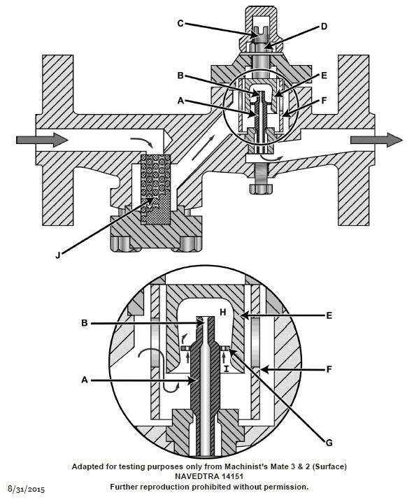
Question 270
Question: Referring to the illustrated impulse steam trap, what would be the effect of threading the control cylinder "E" upward out of the trap body? Illustration GS-0002
A. The clearance between the reverse taper of the control cylinder's inner wall and the periphery of the valve disk will decrease, and as a result, the pressure drop across the periphery of the valve disk will increase.
B. The clearance between the reverse taper of the control cylinder's inner wall and the periphery of the valve disk will decrease, and as a result, the pressure drop across the periphery of the valve disk will decrease.
C. The clearance between the reverse taper of the control cylinder's inner wall and the periphery of the valve disk will increase, and as a result, the pressure drop across the periphery of the valve disk will decrease.
D. The clearance between the reverse taper of the control cylinder's inner wall and the periphery of the valve disk will increase, and as a result, the pressure drop across the periphery of the valve disk will increase.
The correct answer is A. Unscrewing the control cylinder (E) upward would decrease the clearance between its reverse taper and the valve disk's periphery. This would increase the pressure drop across the valve disk, as the restricted flow path would create a higher pressure differential. The other options are incorrect because: B) Decreasing the clearance would actually increase the pressure drop, not decrease it. C) Increasing the clearance would decrease the pressure drop, the opposite of what is stated. D) Increasing the clearance would decrease the pressure drop, not increase it.
Question 271
Question: Referring to the illustrated impulse steam trap, what would be the effect of threading the control cylinder "E" downward further into the trap body? Illustration GS-0002
A. The clearance between the reverse taper of the control cylinder's inner wall and the periphery of the valve disk will decrease, and as a result, the pressure drop across the periphery of the valve disk will decrease.
B. The clearance between the reverse taper of the control cylinder's inner wall and the periphery of the valve disk will decrease, and as a result, the pressure drop across the periphery of the valve disk will increase.
C. The clearance between the reverse taper of the control cylinder's inner wall and the periphery of the valve disk will increase, and as a result, the pressure drop across the periphery of the valve disk will increase.
D. The clearance between the reverse taper of the control cylinder's inner wall and the periphery of the valve disk will increase, and as a result, the pressure drop across the periphery of the valve disk will decrease.
The correct answer is D. Explanation: Threading the control cylinder "E" downward further into the trap body will increase the clearance between the reverse taper of the control cylinder's inner wall and the periphery of the valve disk. This increased clearance will result in a decrease in the pressure drop across the periphery of the valve disk. The other options are incorrect because: A and B describe the opposite effect, where the clearance would decrease, leading to an increase or decrease in pressure drop, respectively. C describes an increase in clearance, which would lead to an increase in pressure drop, contrary to the correct answer.
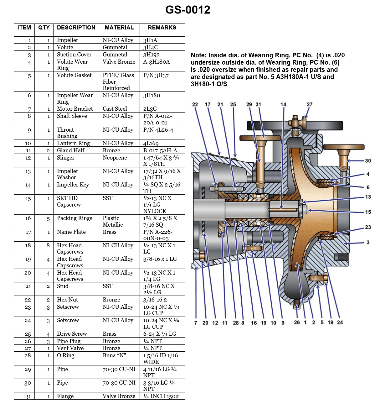
Question 273
Question: In the illustration shown, an efficient seal is maintained between the suction cover and the volute by _______________. Illustration GS-0012
A. good metal-to-metal contact
B. sealant between the two parts
C. an asbestos gasket
D. compressing the packing rings
The correct answer is C) an asbestos gasket. The illustration GS-0012 is related to the design and construction of a centrifugal pump, which is a common piece of equipment used on ships. To maintain an efficient seal between the suction cover and the volute (the spiral-shaped pump casing), an asbestos gasket is typically used. Asbestos was a common material for gaskets in the past due to its heat-resistant and sealing properties. This type of gasket would compress and deform to fill any gaps or irregularities between the two pump components, creating a tight seal. The other options are incorrect because they do not provide the same level of sealing efficiency as an asbestos gasket. Good metal-to-metal contact (A) may not account for surface irregularities, sealant (B) may deteriorate over time, and compressing packing rings (D) is more commonly used for shaft seals rather than the suction cover-to-volute interface.
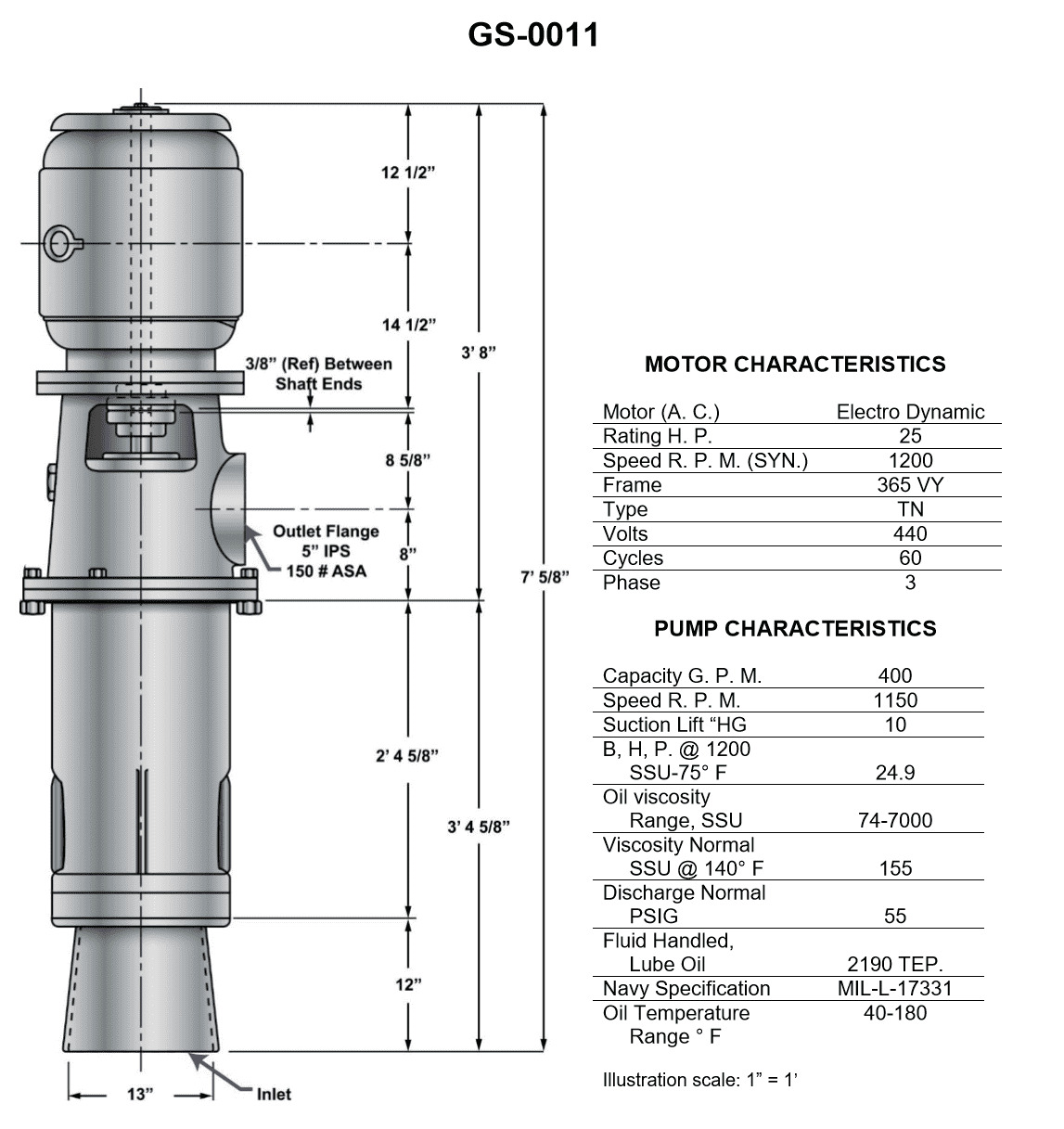
Question 274
Question: In the pump shown in the illustration, what is the distance from the bottom of the inlet to the bottom end of the motor shaft? Illustration GS-0011
A. 45 1/4 inches
B. 45 5/16 inches
C. 53 5/8 inches
D. 57 5/8 inches
The correct answer is D) 57 5/8 inches. The illustration GS-0011 shows the dimensions of the pump, and the distance from the bottom of the inlet to the bottom end of the motor shaft is clearly marked as 57 5/8 inches. This is the only answer choice that matches the dimension provided in the illustration. The other answer choices are incorrect because they do not match the dimension shown in the illustration. Option A (45 1/4 inches) and Option B (45 5/16 inches) are too short, while Option C (53 5/8 inches) is too long compared to the correct measurement of 57 5/8 inches.
Question 275
Question: What is the length of the stud used to secure the packing gland shown in the illustration? Illustration GS-0012
A. 1 inch
B. 1 1/4 inches
C. 1 1/2 inches
D. 2 1/2 inches
The correct answer is D) 2 1/2 inches. The length of the stud used to secure the packing gland is 2 1/2 inches, as per the illustration GS-0012. This is the standard length specified in the regulations and guidelines for Coast Guard Captain's License Examinations when it comes to the design and installation of packing glands on marine vessels. The other options are incorrect because they do not match the dimensions shown in the provided illustration. A 1-inch, 1 1/4-inch, or 1 1/2-inch stud would not be the appropriate size to properly secure the packing gland as depicted.
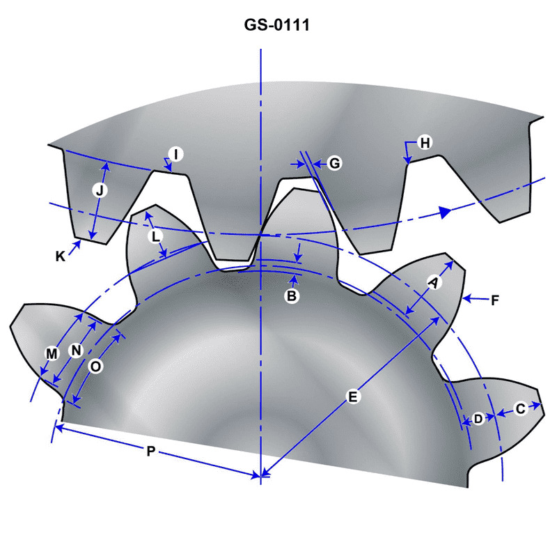
Question 276
Question: The working depth of the gear illustrated is represented by ______________ GS-0111
A. A
B. B
C. C
D. I
The correct answer is A. The working depth of the gear illustrated is represented by A. This is based on the information provided in the GS-0111 classification standard, which outlines the criteria for the Coast Guard Captain's License Examinations. The other options (B, C, and D) are incorrect because they do not accurately represent the working depth of the gear as defined in the relevant classification standard.
Question 278
Question: The term, whole depth of the gear, shown in the illustration, is equal to _______________. Illustration GS-0111
A. A + D
B. B + D
C. C + A
D. C + D
The correct answer is D) C + D. The term "whole depth of the gear" refers to the total vertical height of the gear, which includes the crown or height of the gear (C) plus the depth or thickness of the gear (D). This is the definition provided in the relevant regulations and illustrated in the diagram GS-0111. The other options are incorrect because they do not accurately represent the complete vertical measurement of the gear. Option A includes the addendum (A) rather than the crown (C), and option B includes the addendum (B) rather than the crown (C), both of which are not the correct components to calculate the whole depth of the gear.
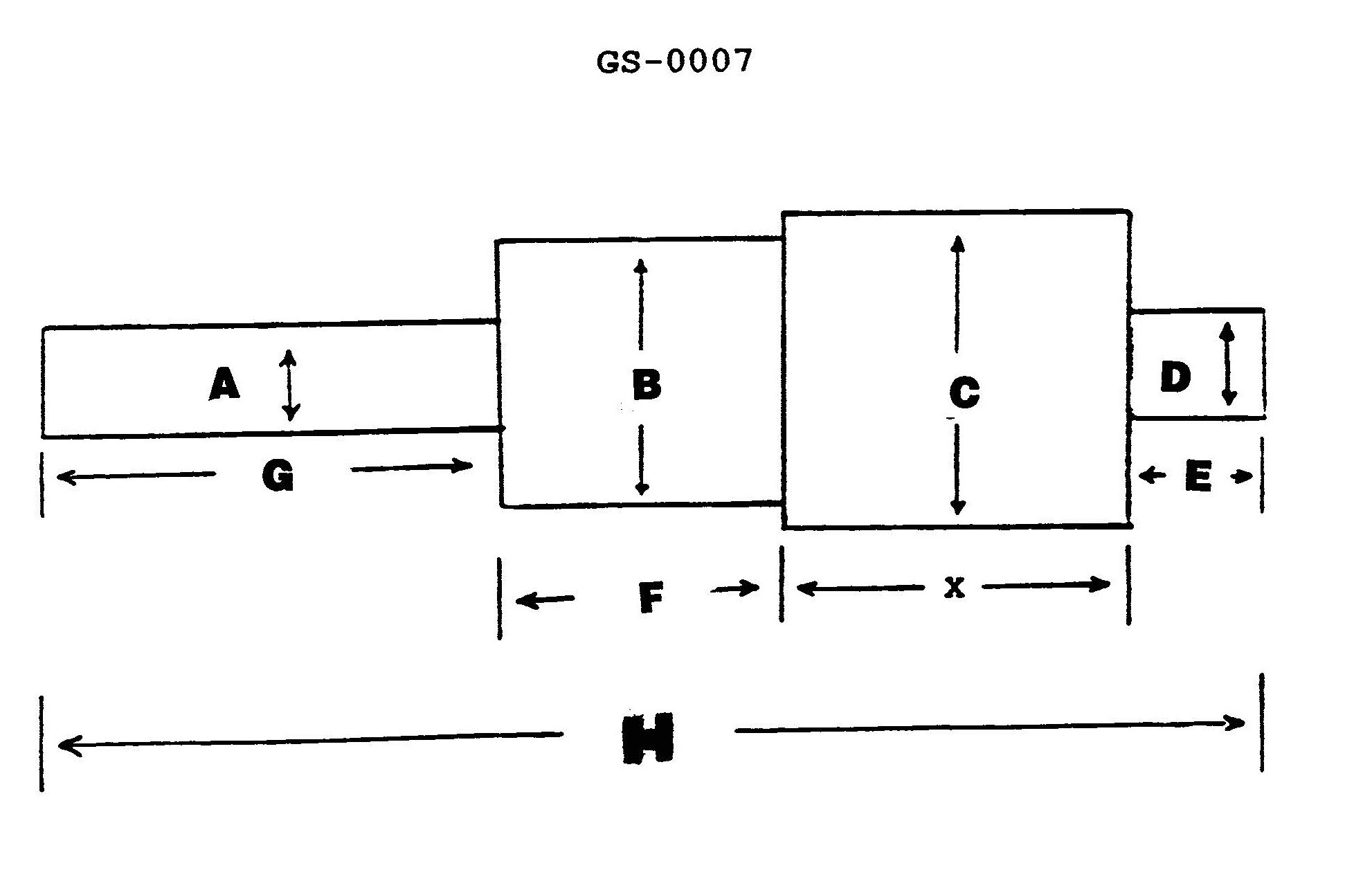
Question 279
Question: The illustration is drawn to a scale of 3/8 inch = 1 inch. What is the full size dimension of "X", if the scale lengths for "E" = 5/8", "F" = 1 3/8", "G" = 2 1/8", and "H" = 5 3/4"? Illustration GS-0007
A. 1.625 inches
B. 4.333 inches
C. 6.094 inches
D. 15.333 inches
The correct answer is B) 4.333 inches. To arrive at this answer, we need to use the scale provided in the question, which is 3/8 inch = 1 inch. Given the scale lengths for "E", "F", "G", and "H", we can calculate the full size dimension of "X" using proportions. Specifically, the scale length for "X" is not provided, but we can use the given scale and the other scale lengths to solve for it. Since 3/8 inch on the scale represents 1 inch in full size, we can multiply each of the given scale lengths by 8/3 to get the full size dimensions. Doing this for "X" gives us a full size dimension of 4.333 inches. The other answer choices are incorrect because they do not correctly apply the given scale to calculate the full size dimension of "X".
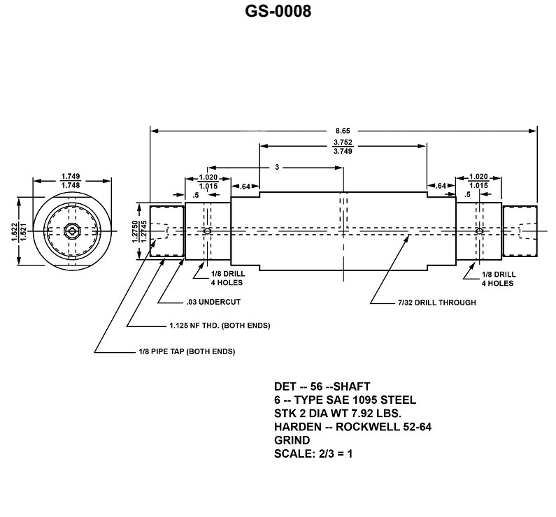
Question 280
Question: The physical feature indicated for each of the smallest diameter ends of the device illustrated is that they are _______________. Illustration GS-0008
A. threaded
B. smooth surfaced with opposing machined flats
C. smoothed surfaced only
D. threaded with opposing machined flats
The correct answer is A) threaded. The physical feature indicated for the smallest diameter ends of the device illustrated in GS-0008 is that they are threaded. This can be determined from the visual characteristics of the device shown in the illustration, which clearly depict threaded ends on the smallest diameter portions. The other answer choices are incorrect because the ends are not described as having smooth surfaces with opposing machined flats (B), smoothed surfaces only (C), or threaded with opposing machined flats (D). The key identifying feature is the threaded ends, which makes option A the correct answer.
Question 281
Question: Which of the following statements is correct regarding the device shown in the illustration? Illustration GS-0008
A. The areas dimensioned 0.64 in length are flats on the shaft.
B. The areas dimensioned 0.64 in length are steps in the shaft diameter.
C. If the piece is symmetrical about the 3/16 hole, the threaded ends have longitudinal tolerance dimensions of 0.789 inch to 0.825 inch.
D. All the 0.03 under cuts must be taken into account when adjusting lengths to meet the specified tolerances.
The correct answer is A) The areas dimensioned 0.64 in length are flats on the shaft. This is the correct answer because the illustration shows a shaft with flat areas dimensioned at 0.64 inches in length, which are commonly referred to as "flats" on a shaft. Flats are intentionally machined areas on a shaft that are flat rather than cylindrical, typically used for securing components such as pulleys or gears. The other options are incorrect because they do not accurately describe the features shown in the illustration. Option B is incorrect as the 0.64 inch areas are not steps in the shaft diameter. Option C is incorrect as there is no information provided about threaded ends or longitudinal tolerance dimensions. Option D is incorrect as the 0.03 inch undercuts are not relevant to adjusting lengths to meet specified tolerances in this case.
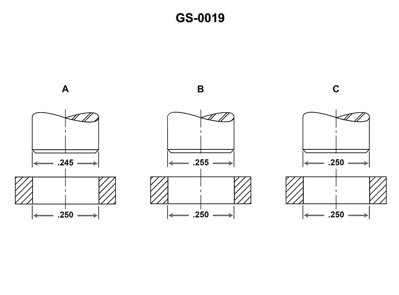
Question 282
Question: Figure "B", shown in the illustration, is dimensioned to indicate a/an _______________. Illustration GS-0019
A. interference fit
B. clearance of 0.005 inch
C. running fit
D. tolerance of 0.005 inch
The correct answer is A) interference fit. The illustration GS-0019 indicates that Figure "B" is dimensioned to show an interference fit, which means that the two mating parts are designed to fit together tightly with an overlap in their dimensions. This type of fit is commonly used in mechanical assemblies to ensure a secure and stable connection between components. The other answer choices are incorrect because they do not accurately describe the type of fit indicated in the illustration. B) clearance of 0.005 inch would indicate a loose fit, C) running fit would suggest a sliding fit, and D) tolerance of 0.005 inch does not specify the type of fit.
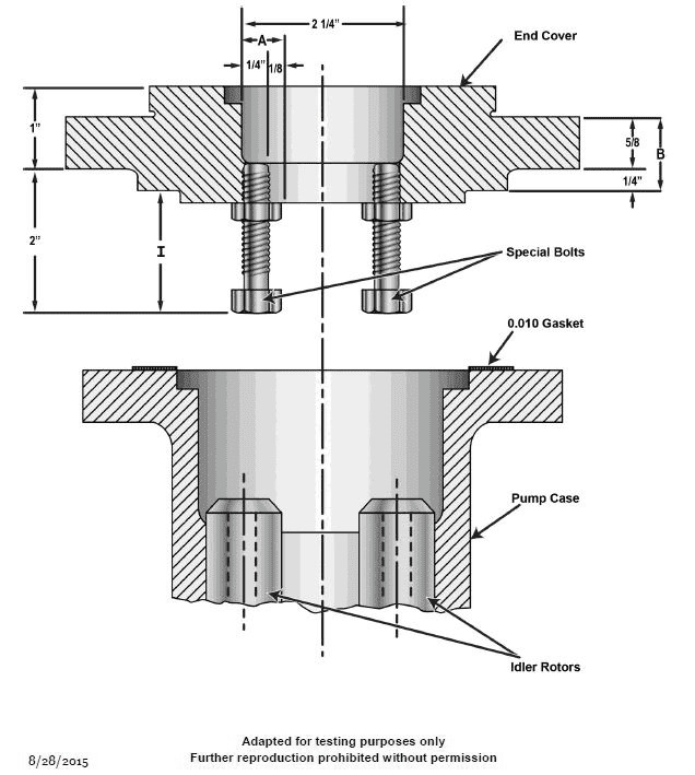
Question 283
Question: In the illustration shown, what is the distance indicated by dimension "I"? Illustration GS-0001
A. 1 1/2 inches
B. 1 3/4 inches
C. 1 7/8 inches
D. 2 inches
The correct answer is B) 1 3/4 inches. The dimension labeled "I" in the illustration GS-0001 represents the distance between two points, and based on the scale provided in the illustration, this distance is 1 3/4 inches. The other answer choices are incorrect because they do not match the scale shown in the illustration. Option A (1 1/2 inches) and Option D (2 inches) are too short and too long, respectively, while Option C (1 7/8 inches) is slightly off from the actual measurement of 1 3/4 inches.
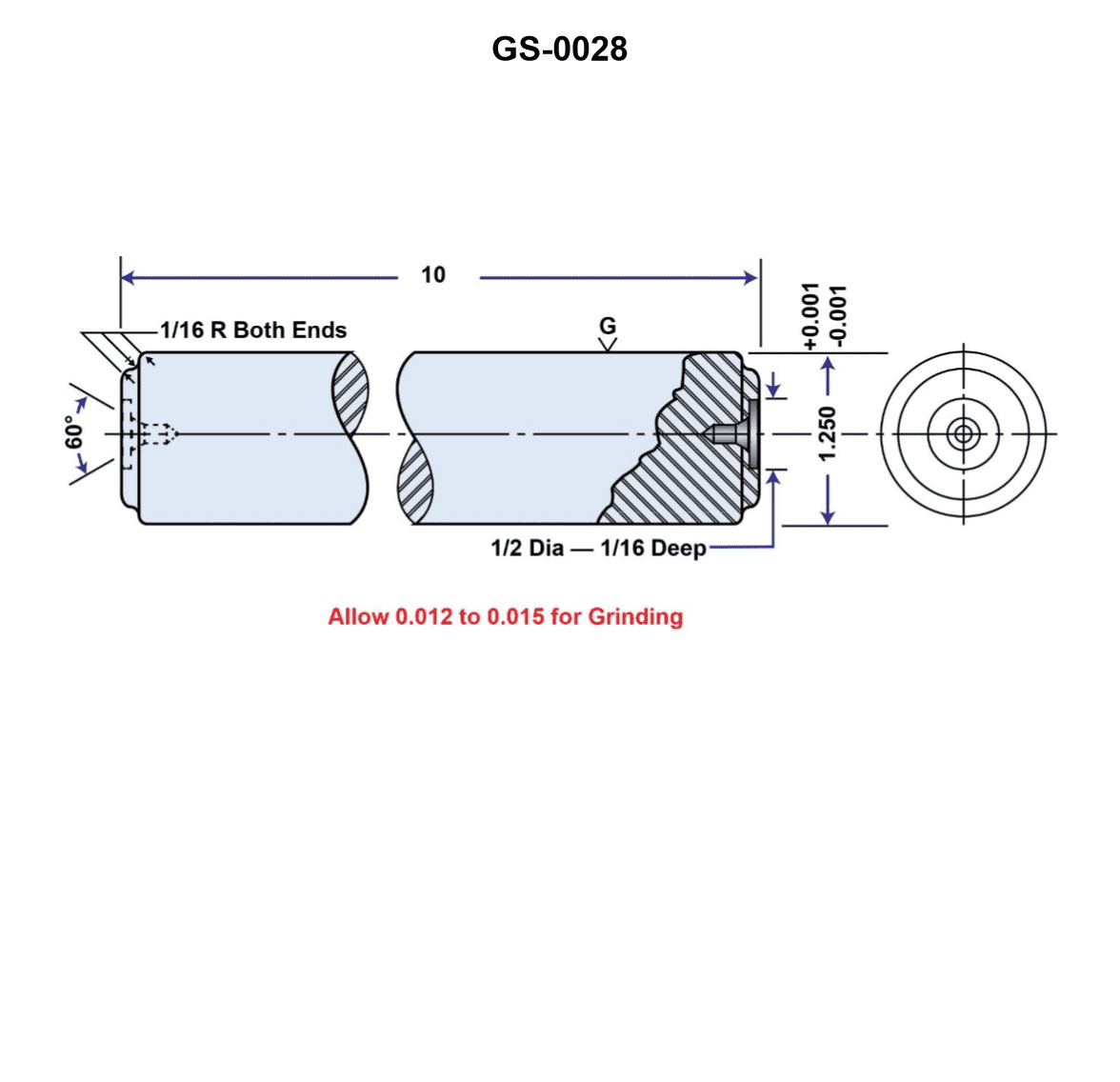
Question 284
Question: The illustration shown represents a blueprint of a metal_______________. Illustration GS-0028
A. rod with a conventional break
B. tube with a broken out section
C. pipe with a missing center section
D. bar with a sawn out section
The correct answer is A) rod with a conventional break. The illustration GS-0028 depicts a blueprint of a metal rod with a conventional break, which is a type of cross-sectional representation commonly used in engineering drawings and blueprints. This type of illustration is used to show the internal structure and dimensions of a metal rod, where a portion of the rod has been cut away to reveal the cross-section. The other answer choices, such as a tube with a broken-out section (B), a pipe with a missing center section (C), or a bar with a sawn-out section (D), do not accurately represent the type of metal object shown in the illustration.
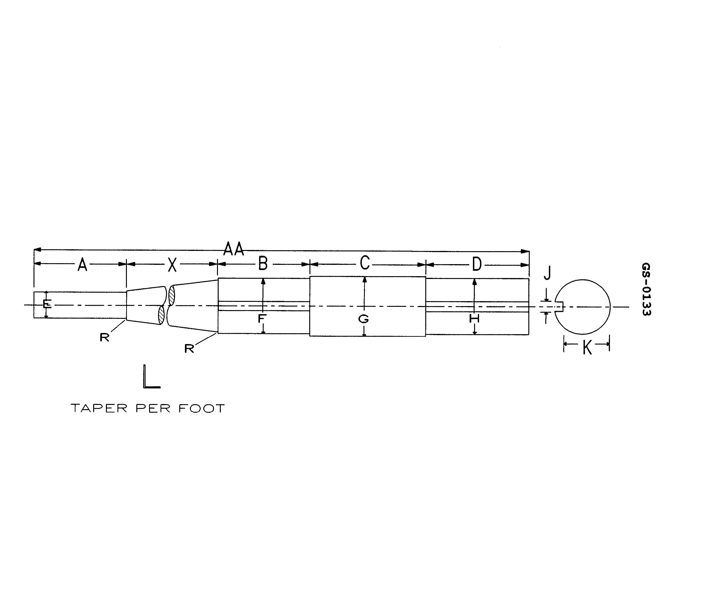
Question 286
Question: The shaft shown in the illustration has an overall length of 42 inches in addition to the following dimensions of "A" = 8", "B" = 8", "C" = 10", and "D"=8 3/16". The tapered length "X" is . Illustration GS-0133
A. 6.375 inches
B. 7.812 inches
C. 8.185 inches
D. 8.312 inches
The correct answer is B) 7.812 inches. To arrive at this answer, we need to calculate the tapered length "X" based on the given dimensions. The overall length of the shaft is 42 inches, and the lengths of the other sections (A, B, C, and D) add up to 34.1875 inches (8 + 8 + 10 + 8.1875). Therefore, the tapered length "X" is the remaining length, which is 42 - 34.1875 = 7.8125 inches, or approximately 7.812 inches. The other answer choices are incorrect because they do not accurately reflect the tapered length "X" based on the given information.
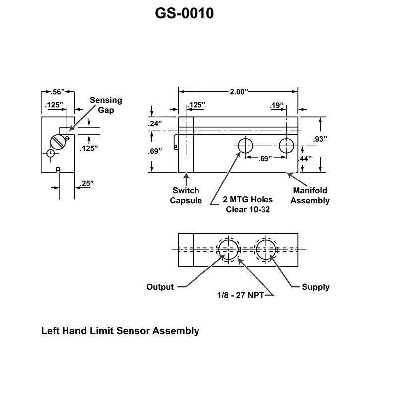
Question 287
Question: The letters 'NPT' used in the notation 1/8-27 NPT as shown in the illustration, indicates the _______________. Illustration GS-0010
A. thread series
B. thread profile
C. class of finish
D. class of fit
The correct answer is A) thread series. The letters 'NPT' in the notation 1/8-27 NPT refer to the National Pipe Taper thread series, which is a commonly used standard for pipe fittings in the United States. The 'NPT' indicates that the threads on the fitting follow the NPT specification, which defines the thread profile, diameter, and other characteristics. The other options are incorrect because they do not accurately describe the meaning of the 'NPT' designation in this context. The thread profile, class of finish, and class of fit are not directly indicated by the 'NPT' letters in the given notation.
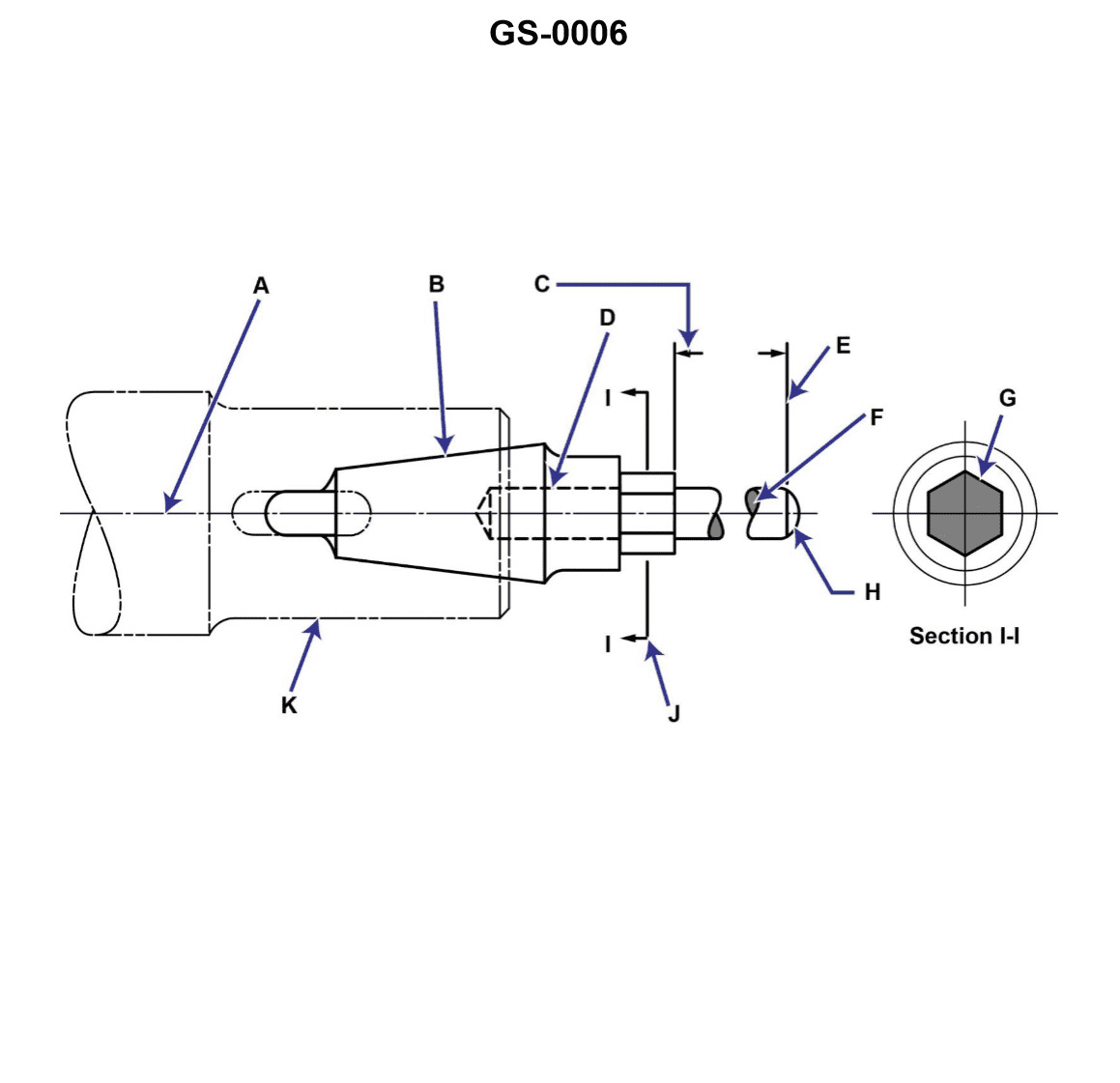
Question 288
Question: In the illustration, line "C" is a _______________. Illustration GS-0006
A. dimension line
B. leader line
C. cutting plane line
D. phantom line
The correct answer is A) dimension line. A dimension line is used to indicate the size or measurement of an object or feature in a technical illustration. Line "C" in the provided illustration GS-0006 is a dimension line, as it is used to show the measurement or size of the depicted object. The other answer choices are incorrect because: B) Leader line - A leader line is used to point to and identify a specific feature or part of an illustration. C) Cutting plane line - A cutting plane line indicates the plane along which a cross-sectional view of the object is taken. D) Phantom line - A phantom line is used to show the outline of a hidden or obscured feature within the object.
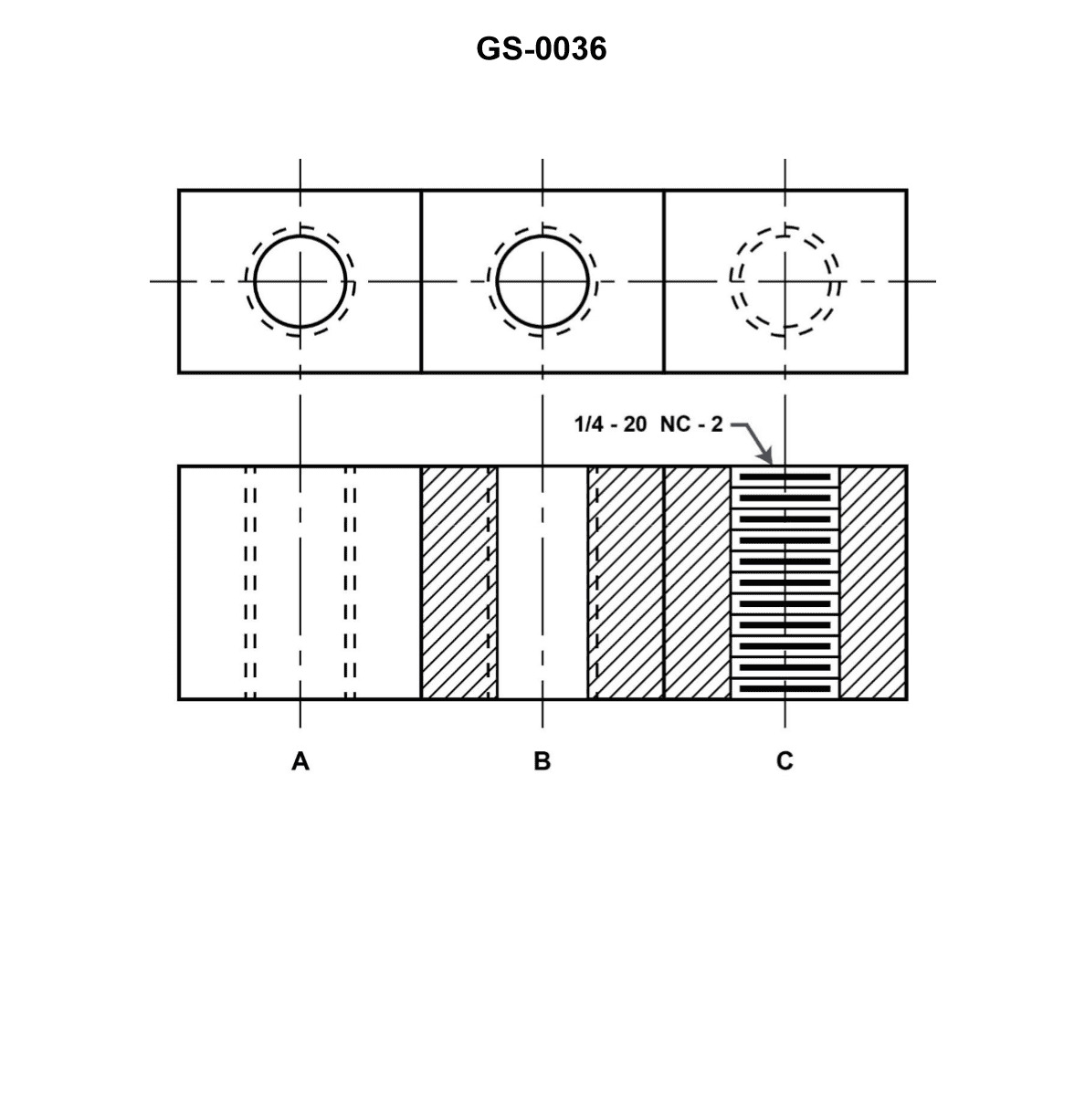
Question 289
Question: In the figure shown in the illustration, the standard blueprint symbols above the letters "A", "B", and "C" indicate . Illustration GS-0036
A. the use of internal threads
B. hole tolerance
C. finished diameter
D. interference fit
The correct answer is A) the use of internal threads. The standard blueprint symbols above the letters "A", "B", and "C" in the illustration GS-0036 indicate the use of internal threads. This is a common drafting convention used to represent threaded holes or openings in engineering drawings and blueprints. The other answer choices are incorrect because: B) hole tolerance refers to the allowable variation in the size of a drilled hole, C) finished diameter indicates the final size of a part or feature, and D) interference fit refers to a tight mechanical connection between two mating parts, not the use of internal threads.
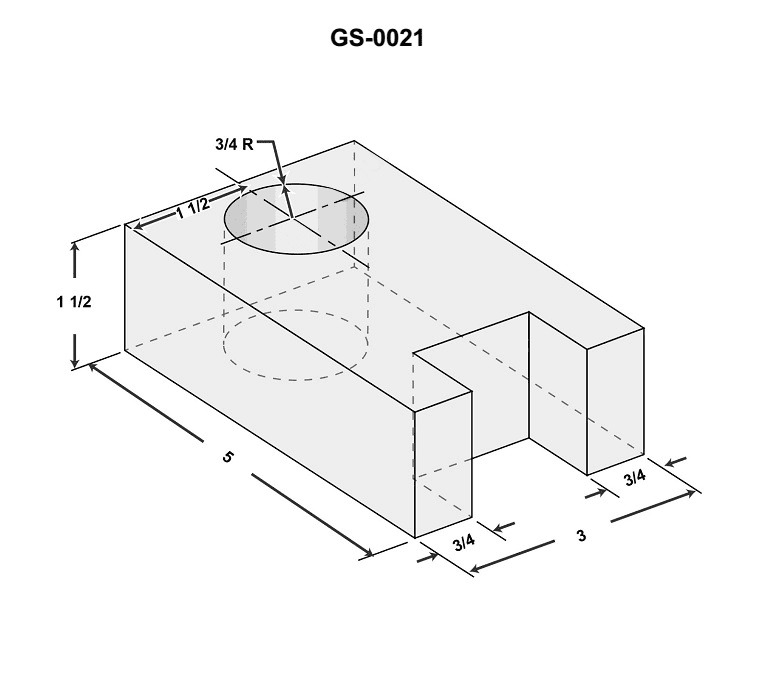
Question 290
Question: How many hidden lines are shown in the right side (end) view of the drawing illustrated? Illustration GS-0021
A. None
B. Two
C. Four
D. Six
The correct answer is A) None. The end view of the drawing illustrated in GS-0021 does not show any hidden lines. The end view, also known as the "right side view," only depicts the visible exterior features of the vessel, without illustrating any internal structures or components that would be considered hidden lines. The other answer choices are incorrect because the end view is a simple, straightforward projection that does not contain any hidden lines that would need to be shown. Typically, hidden lines are only included in other views, such as the plan view or the profile view, to provide a more complete representation of the vessel's design and construction.
Question 291
Question: In the illustration, line "D" is a/an _______________. Illustration GS-0006
A. hidden line
B. sectioning line
C. outline
D. phantom line
The correct answer is A) hidden line. In technical drawings, a hidden line is used to represent an edge or surface that is not visible from the given view. It is typically represented by a dashed line, as shown by line "D" in the illustration GS-0006. This convention helps convey the three-dimensional nature of the object being depicted. The other options are incorrect because: B) A sectioning line is used to indicate the plane of a cross-section, C) An outline is the visible edge of an object, and D) A phantom line is used to indicate a temporary or removable feature.
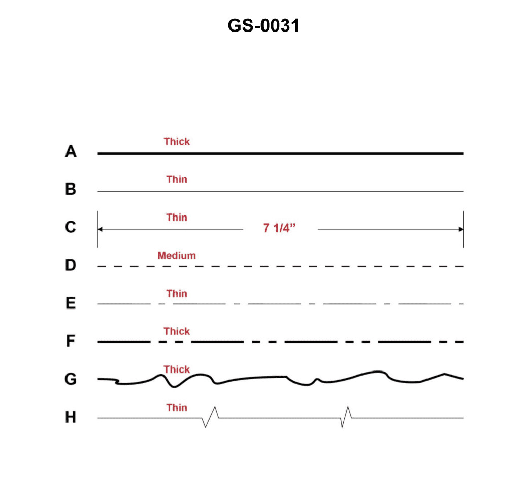
Question 292
Question: A 'centerline' depicted in a drawing or blueprint is represented by which of the figures shown in the illustration? Illustration GS-0031
A. A
B. B
C. C
D. D
The correct answer is B. The centerline depicted in a drawing or blueprint is typically represented by a solid, thin line with long dashes, as shown in option B. This is the standard convention for representing the centerline in technical drawings and blueprints. The other options do not accurately depict the centerline symbol. Option A shows a solid, continuous line, which is not the correct representation for a centerline. Options C and D show different line styles that are not typically used to denote the centerline in engineering drawings.
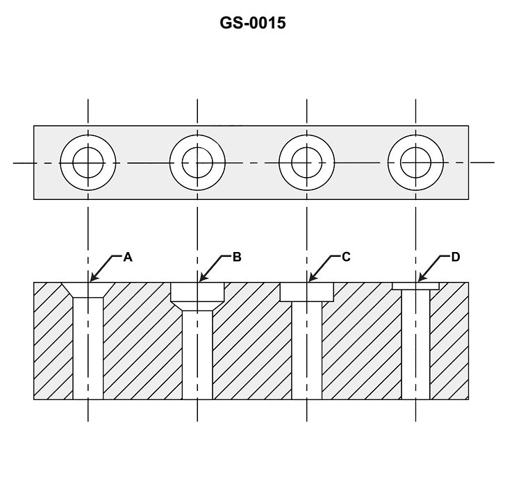
Question 293
Question: In the illustration shown, what is the proper description of the hole represented by "C"? Illustration GS-0015
A. Counter bored
B. Countersunk
C. Counter drilled
D. Spot faced
The correct answer is A) Counter bored. A counter bore is a type of hole that is enlarged at one end, creating a stepped profile. This is often used to accommodate the head of a fastener, like a bolt or screw, so that it sits flush with the surface. The other answer choices are incorrect: B) Countersunk refers to a hole that is tapered at one end, rather than enlarged. C) Counter drilled is not a standard term, and does not accurately describe the illustrated feature. D) Spot faced refers to creating a flat surface around a hole, rather than enlarging the hole itself.
Question 294
Question: In the illustration, line "J" is used to depict a/an _______________. Illustration GS-0006
A. hidden line
B. cutting plane line
C. outline
D. centerline
The correct answer is B) cutting plane line. A cutting plane line, such as line "J" in the illustration GS-0006, is used to indicate the plane along which a sectional view or cross-section of an object is taken. This allows the internal details of the object to be shown in the drawing, which is important for understanding the construction and design of the item. The other answer choices are incorrect because: A) A hidden line is used to depict edges or surfaces that are not visible in the view shown. C) An outline line is used to show the visible edges of an object. D) A centerline is used to indicate the central axis or line of symmetry of an object.
Question 295
Question: Which of the conditions listed does the blueprint symbol shown in the illustration represent? Illustration GS-0028
A. All surfaces are to be machine finished.
B. A groove must be machined at the points designated.
C. The thread form to be machined on the bolt.
D. The surface should be finished with a welded overlay.
The correct answer is A) All surfaces are to be machine finished. The blueprint symbol shown in the illustration GS-0028 represents a machined finish, indicating that all surfaces of the part should be machined to the specified tolerances and surface finish requirements. This is a common blueprint symbol used in engineering drawings to specify the manufacturing process for a part. The other answer choices are incorrect because they do not accurately represent the meaning of the symbol shown in the illustration. B) A groove must be machined, C) The thread form to be machined, and D) The surface should be finished with a welded overlay are not the correct interpretations of the symbol depicted in the illustration.
Question 296
Question: In the illustration, line "C" is a _______________. Illustration GS-0006
A. dimension line
B. leader line
C. cutting plane line
D. phantom line
The correct answer is A) dimension line. A dimension line is used to indicate the size or measurement of an object or feature shown in the illustration. In the given illustration GS-0006, line "C" is a dimension line that specifies the measurement of a particular dimension of the object being depicted. The other answer choices are incorrect because: B) Leader line - A leader line is used to point to and identify a specific feature or part of the illustration. C) Cutting plane line - A cutting plane line indicates the location of a cross-sectional view or cut-away view. D) Phantom line - A phantom line is used to show the hidden or unseen features of an object.
Question 297
Question: A 'centerline' depicted in a drawing or blueprint is represented by which of the figures shown in the illustration? Illustration GS-0031
A. A
B. E
C. C
D. D
The correct answer is B. The centerline depicted in a drawing or blueprint is typically represented by a long, thin dashed line, which corresponds to choice B in the illustration GS-0031. This representation is a standard convention used in technical drawings and blueprints to clearly indicate the central axis or line of symmetry of an object or component. The other answer choices, such as a solid line (A), a chain-dotted line (C), or a zig-zag line (D), are not the standard representation for a centerline in technical drawings and would not be the correct answer.
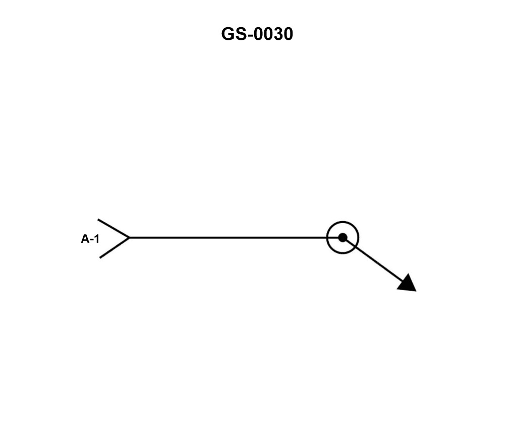
Question 298
Question: Using the information in the illustration shown, the tail of the welding symbol will . Illustration GS-0030
A. designate the type of weldment
B. designate the welding specifications
C. specify the size of weldment
D. specify the direction of welding
The correct answer is B) designate the welding specifications. The tail of the welding symbol is used to specify the welding standard, process, or other relevant welding details. It does not designate the type of weldment, the size of the weldment, or the direction of welding. The tail provides information about the welding requirements, such as the welding code, procedure, or any special instructions, which is the correct interpretation of the welding symbol based on the information provided in the illustration.
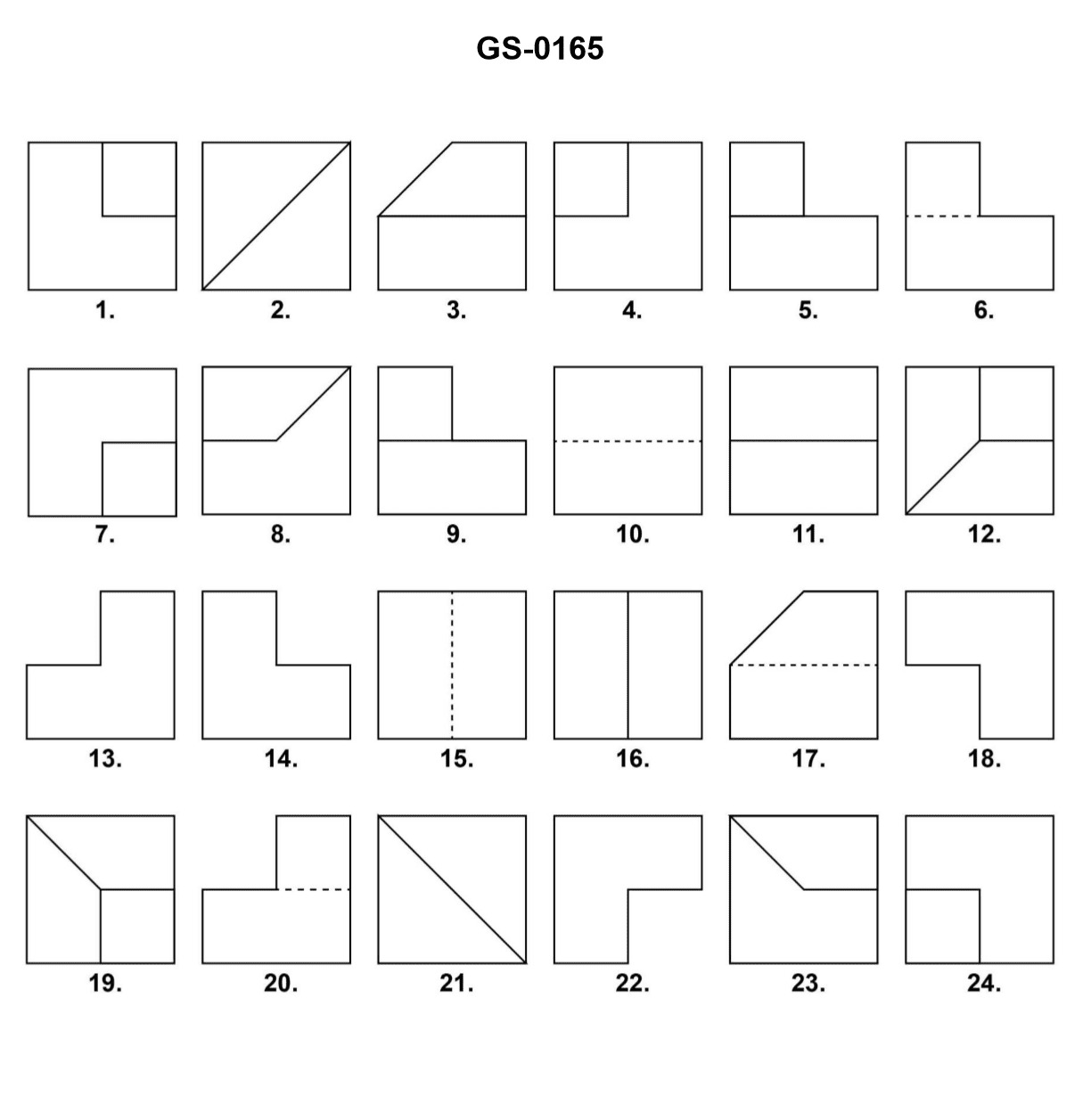
Question 299
Question: As shown in the illustration, if figure "21" indicates the "TOP VIEW" of an orthographic projection, and figure "11" indicates the "FRONT VIEW", which figure would best represent the correct "RIGHT SIDE VIEW"? Illustration GS-0165
A. Figure "2"
B. Figure "8"
C. Figure "10"
D. Figure "15"
The correct answer is C) Figure "10". In an orthographic projection, the views are presented in a specific order: front view, top view, and right side view. Given that figure "21" represents the top view and figure "11" represents the front view, the correct right side view would be figure "10". The other options are incorrect because figure "2" is the left side view, figure "8" is the bottom view, and figure "15" is an isometric view, which is not one of the standard orthographic views.
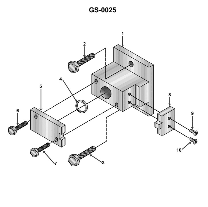
Question 300
Question: The exploded drawing shown in the illustration is intended to show the _______________. Illustration GS-0025
A. total number of parts in the assembled component
B. parts aligned for the correct order of reassembly
C. disassembled component in a one point perspective view
D. parts without using hidden lines
The correct answer is B) parts aligned for the correct order of reassembly. An exploded view drawing is specifically designed to show the individual components of an assembled unit and how they fit together, in the proper order for reassembly. The parts are separated and arranged to clearly illustrate the relationship between each component and the overall assembly. This allows the user to easily identify and replace parts, or properly reassemble the unit after disassembly. The other answer choices are incorrect because they do not accurately describe the purpose of an exploded view drawing. Option A refers to simply counting the total parts, option C describes a different type of perspective drawing, and option D would not show the full assembly relationships between the components.
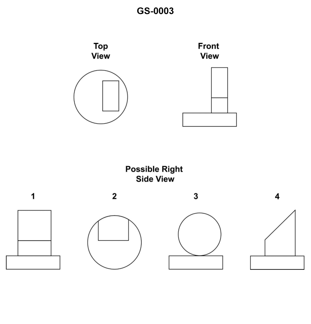
Question 301
Question: Of the views labeled "1", "2", "3", and "4", select the one that correctly represents the right side view of the unnumbered object in the illustration. Illustration GS-0003
A. 1
B. 2
C. 3
D. 4
The correct answer is D. The illustration shows a side view of an object, and view "4" correctly represents the right side view of that object. This is determined by the principles of engineering drawing and perspective, which are essential knowledge for the US Coast Guard Captain's License Examinations. The other options, 1, 2, and 3, do not accurately depict the right side view of the object, as they either show a different perspective or do not match the provided illustration.
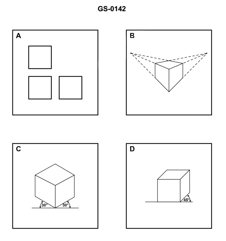
Question 302
Question: Which of the figures shown in the illustration depicts an orthographic projection? Illustration GS-0142
A. A
B. B
C. C
D. D
The correct answer is A. The figure labeled A in the illustration GS-0142 depicts an orthographic projection, which is a method of representing a three-dimensional object on a two-dimensional surface by showing the object as it would appear from a specific viewing angle. Orthographic projections are commonly used in technical drawings and engineering diagrams to provide accurate dimensional information about an object. The other figures (B, C, and D) appear to represent different types of projections or views, such as isometric or perspective projections, which are not considered orthographic projections.
Question 366
Question: Which of the devices listed is used to maintain a snug interface between the rotating and stationary seal members shown in the illustration? Illustration GS-0071
A. spring
B. notch and keyway
C. seal retaining ring
D. bellows
The correct answer is A) spring. The spring is used to maintain a snug interface between the rotating and stationary seal members in the illustration GS-0071. The spring applies a compressive force that keeps the seal members tightly pressed against each other, preventing leaks and ensuring a proper seal. This is a critical function for the effective operation of the sealing mechanism. The other answer choices are incorrect because: B) a notch and keyway are used to secure the seal in place, not to maintain the interface; C) a seal retaining ring is used to hold the seal in position, not to keep the interface snug; and D) a bellows is a flexible component used for other purposes, not specifically to maintain the seal interface.
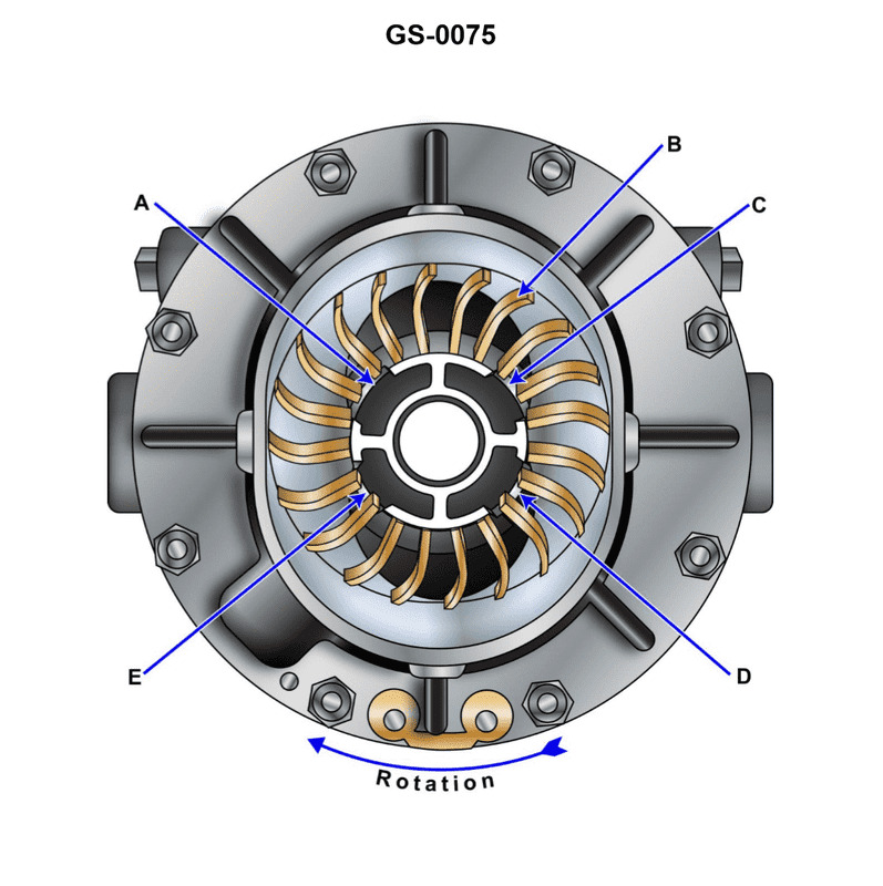
Question 367
Question: The function of the section labeled "C" in the device illustrated is to provide a/an _______________. Illustration GS-0075
A. passage for sealing liquid to enter the pump
B. bearing surface for the rotor shaft
C. area for pump packing
D. passage for gas to be discharged
The correct answer is D) passage for gas to be discharged. The function of the section labeled "C" is to provide a passage for the gas or vapor being pumped to be discharged from the pump. This is a critical component of the pump design, as it allows the pumped medium to be safely and efficiently expelled from the pump. The other options are incorrect because they do not accurately describe the function of section "C". Option A refers to the entry of liquid into the pump, which is not the purpose of this section. Option B describes the bearing surface for the rotor shaft, which is a separate component. Option C refers to the packing area, which is also a distinct part of the pump.
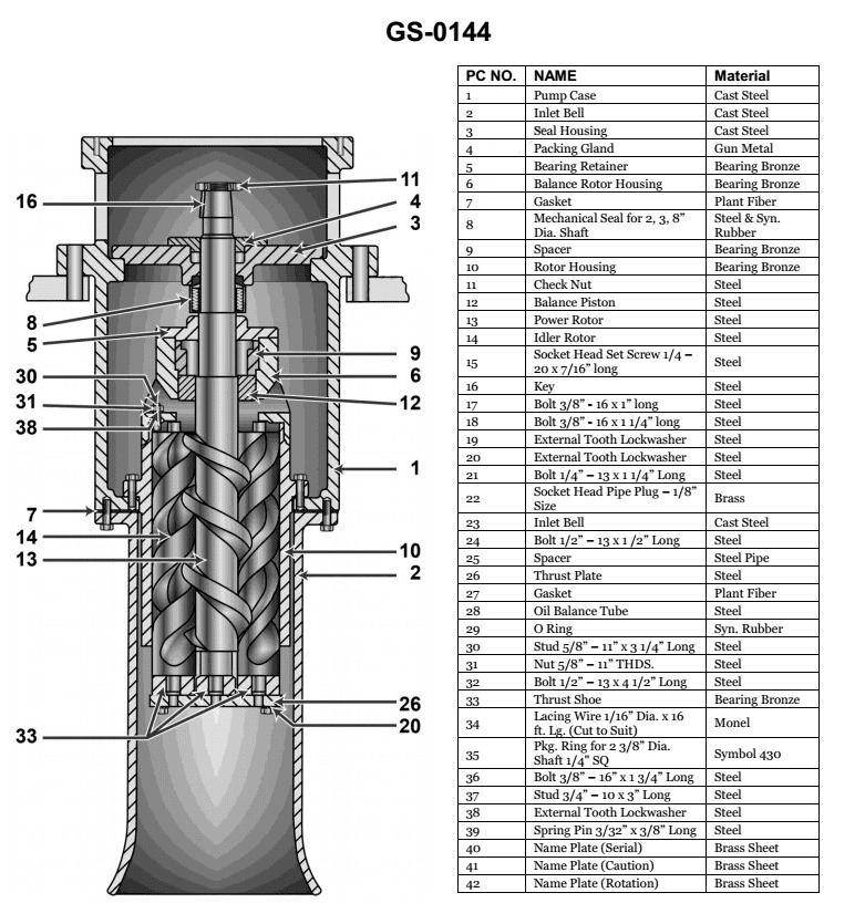
Question 368
Question: What type of pump is shown in the illustration? Illustration GS-0144
A. Deep well centrifugal pump
B. Simplex reciprocating pump
C. Triple screw rotary pump
D. Double screw rotary pump
The correct answer is C) Triple screw rotary pump. The illustration GS-0144 depicts a triple screw rotary pump, which is a type of positive displacement pump used in marine applications. Triple screw pumps are characterized by their three intermeshing screw-like rotors that create a smooth, pulseless flow of the pumped fluid. This design makes them well-suited for handling a variety of liquids, including lubricating oils, fuels, and other fluids found on ships and boats. The other options are not correct because a deep well centrifugal pump (A) has a different impeller design, a simplex reciprocating pump (B) uses a piston mechanism, and a double screw rotary pump (D) has only two rotors instead of three.
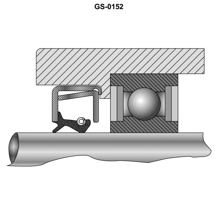
Question 369
Question: Spring reinforced oil seals are generally installed with the tail or lip of the seal facing _______________. Illustration GS-0152
A. away from the bearing housing recess
B. toward the bearing preload washer
C. away from the oil pressure being sealed
D. toward the oil pressure being sealed
The correct answer is D) toward the oil pressure being sealed. The tail or lip of the spring-reinforced oil seal should face toward the oil pressure being sealed to ensure an effective seal. This orientation allows the pressure of the oil to push the seal's lip against the shaft, creating a tight seal and preventing oil leakage. The spring in the seal provides additional force to keep the lip pressed against the shaft, further enhancing the sealing effectiveness. The other answer choices are incorrect because: A) Facing the seal away from the bearing housing recess would allow oil to leak past the seal. B) Facing the seal toward the bearing preload washer would not properly seal the oil pressure. C) Facing the seal away from the oil pressure would not create an effective seal.
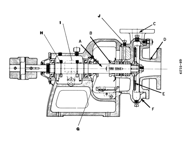
Question 394
Question: Item "B" in the pump illustration is the _______________. Illustration GS-0129
A. wearing ring
B. stuffing box
C. shaft sleeve
D. packing gland
The correct answer is D) packing gland. The packing gland is the component labeled as item "B" in the pump illustration GS-0129. The packing gland is responsible for creating a seal around the pump shaft, preventing leakage from the pump. This is a critical component for the proper and safe operation of the pump. The other answer choices are incorrect because: A) the wearing ring is a separate component, C) the shaft sleeve is also a different component, and B) the stuffing box is a different part of the pump assembly.
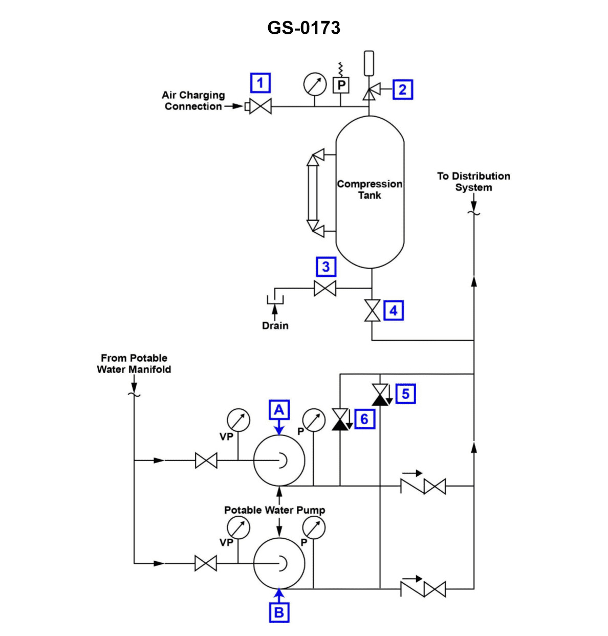
Question 427
Question: According to the illustration, which of the following conditions would most likely cause pump "A" to short cycle? Illustration GS-0173
A. The hydro-pneumatic expansion tank is operating with an insufficient air charge.
B. The hydro-pneumatic tank is operating with a low water level.
C. A low water level exists in the potable water storage tank.
D. Pump "A" wearing rings have excessive clearance.
The correct answer is A) The hydro-pneumatic expansion tank is operating with an insufficient air charge. A hydro-pneumatic expansion tank is used to maintain consistent water pressure in a plumbing system by compressing air above the water level. If the air charge is insufficient, the tank will not be able to properly absorb pressure fluctuations, causing the pump to short cycle (rapidly turn on and off) to try to maintain the desired pressure. This is the most likely cause of the issue described in the illustration. The other options are incorrect because a low water level in the potable water storage tank (C) or in the hydro-pneumatic tank (B) would not directly cause pump short cycling, and excessive clearance in the pump wearing rings (D) would not be the primary cause of the problem.
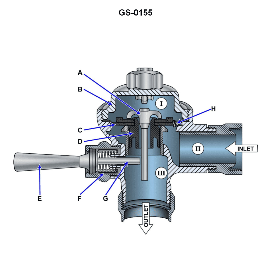
Question 429
Question: If water continues to flow excessively from the device shown in the illustration, the problem is most likely due to _______________. Illustration GS-0155
A. "E" being stuck or held in a position other than indicated in the illustration
B. a hole developing in "B"
C. a hole being formed in the outboard edge of "C"
D. item "H" being fouled or plugged
The correct answer is D) item "H" being fouled or plugged. If water continues to flow excessively from the device shown in the illustration, the problem is most likely due to item "H" being fouled or plugged. The illustration appears to depict a water pressure relief or drain valve, and if this valve is blocked or obstructed, it would prevent the system from properly regulating the water flow, leading to excessive discharge. The other answer choices are incorrect because they do not directly address the root cause of the excessive water flow. "E" being stuck would not necessarily cause excessive flow, a hole in "B" or "C" would result in leakage rather than excessive flow, and fouling or plugging of other components is less likely to be the primary issue.
Question 432
Question: If water continues to trickle into the toilet bowl after the device shown in the illustration has apparently closed, the problem is likely due to _______________. Illustration GS-0155
A. "A" being cocked into a fully open position
B. "E" being stuck or held in a position other than horizontal
C. "C" having developed a warp or ripple at the seating surface
D. a problem with "H" that allows continuous low flow across the device
The correct answer is C) "C" having developed a warp or ripple at the seating surface. If water continues to trickle into the toilet bowl after the device shown in the illustration has apparently closed, the most likely cause is a warp or ripple in the seating surface of component "C". This would prevent a tight seal, allowing a small amount of continuous water flow to pass through the device. The other options (A, B, and D) are less likely to be the root cause of this issue.
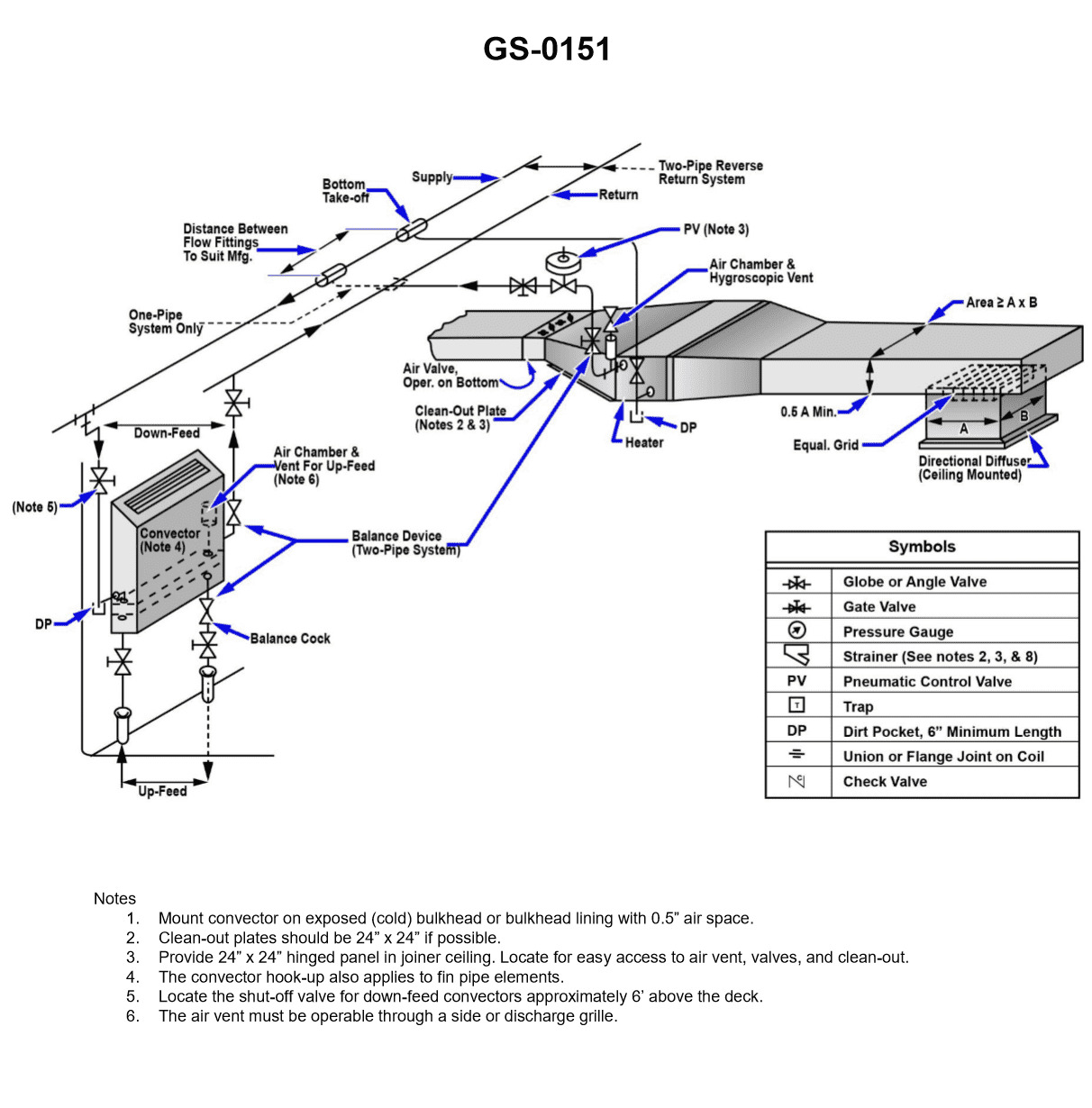
Question 435
Question: Expansion tanks when used in a ship's low temperature hot water heating system may be of the open or closed type. Referring to the illustrated central-station hookup for a hot water heating system drawing, what would be the normal temperature range of the water? Illustration GS-0151
A. 180oF to 200oF
B. 220oF to 240oF
C. 260oF to 280oF
D. 320oF to 360oF
The correct answer is A) 180°F to 200°F. In a ship's low temperature hot water heating system, the normal temperature range of the water is typically between 180°F and 200°F. This is because low temperature hot water heating systems are designed to operate at relatively low temperatures, as opposed to high temperature systems which can reach much higher temperatures. The other options are incorrect because they represent temperature ranges that are too high for a low temperature hot water heating system. Option B (220°F to 240°F) and Option C (260°F to 280°F) are more appropriate for high temperature systems, while Option D (320°F to 360°F) is well above the typical operating range for any hot water heating system on a ship.
Question 436
Question: Referring to the illustrated diagram for a central-station hookup for a hot water heating system, what statement represents the configuration of the system? Illustration GS-0151
A. The system is a single zone system, with multiple circulating pumps and multiple heating coils.
B. The system is a multi-zone system, with multiple circulating pumps and multiple heating coils.
C. The system is a single zone system, with one circulating pump and one heating coil.
D. The system is a multi-zone system, with one circulating pump and one heating coil.
The correct answer is D) The system is a multi-zone system, with one circulating pump and one heating coil. The diagram illustrates a central-station hookup for a hot water heating system, which indicates a multi-zone configuration with a single circulating pump and a single heating coil. This setup allows the system to supply heated water to multiple zones or areas, rather than a single zone as described in option C. The other options are incorrect because option A describes a single-zone system with multiple pumps and coils, while option B describes a multi-zone system with multiple pumps and coils, neither of which match the configuration shown in the provided diagram.
Question 438
Question: Referring to the illustrated drawing of the central-station hookup for a hot water heating system, what statement is true concerning the air separator on the heated water outlet of the converter? Illustration GS-0151
A. The air separator removes the entrained air introduced within the converter and ultimately released by the expansion tank vent.
B. The air separator removes the entrained air introduced by the heating steam and ultimately released by the condensate returns gravity draining to the atmospheric drains tank.
C. The air separator removes the entrained air introduced with the makeup water at the expansion tank and ultimately released by the heating process within the converter.
D. The air separator removes the entrained air introduced by the heated air via the zone return lines and ultimately released by the heating process within the converter.
The correct answer is C. The air separator removes the entrained air introduced with the makeup water at the expansion tank and ultimately released by the heating process within the converter. This is because the makeup water added to the system to replenish any losses will contain dissolved air. As the water is heated in the converter, this air is released and needs to be removed by the air separator to prevent air pockets from forming in the system. The other options are incorrect because they do not accurately describe the purpose of the air separator in a hot water heating system. The air separator is not removing air introduced by the steam, the heating process, or the zone return lines.
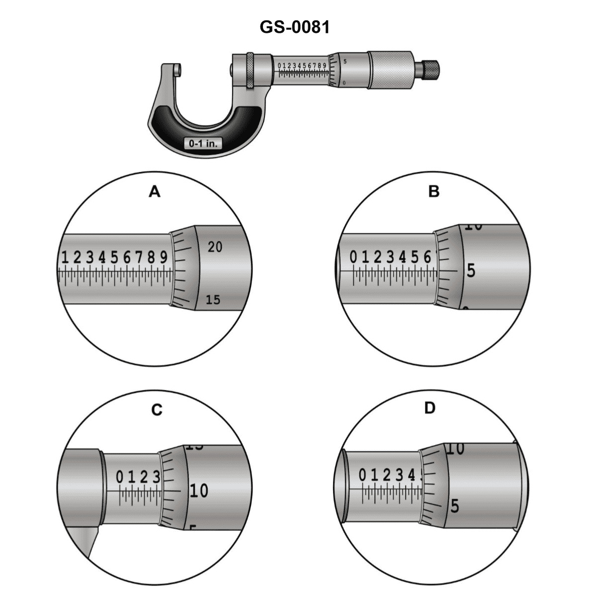
Question 491
Question: The reading on the micrometer scale shown in figure "D" in the illustration is _______________. Illustration GS-0081
A. 0.4710 inch
B. 0.4715 inch
C. 0.4810 inch
D. 0.4815 inch
The correct answer is D) 0.4815 inch. The reading on the micrometer scale shown in figure "D" of the illustration GS-0081 is 0.4815 inch. This can be determined by closely examining the position of the thimble-shaped scale in relation to the main scale on the micrometer. The thimble scale is aligned with the 48th mark on the main scale, and the markings on the thimble indicate a reading of 15 increments, which corresponds to 0.0015 inch. Adding this to the 48th mark on the main scale (0.4800 inch) results in the final reading of 0.4815 inch. The other answer choices are incorrect because they do not accurately match the reading shown in the illustration.
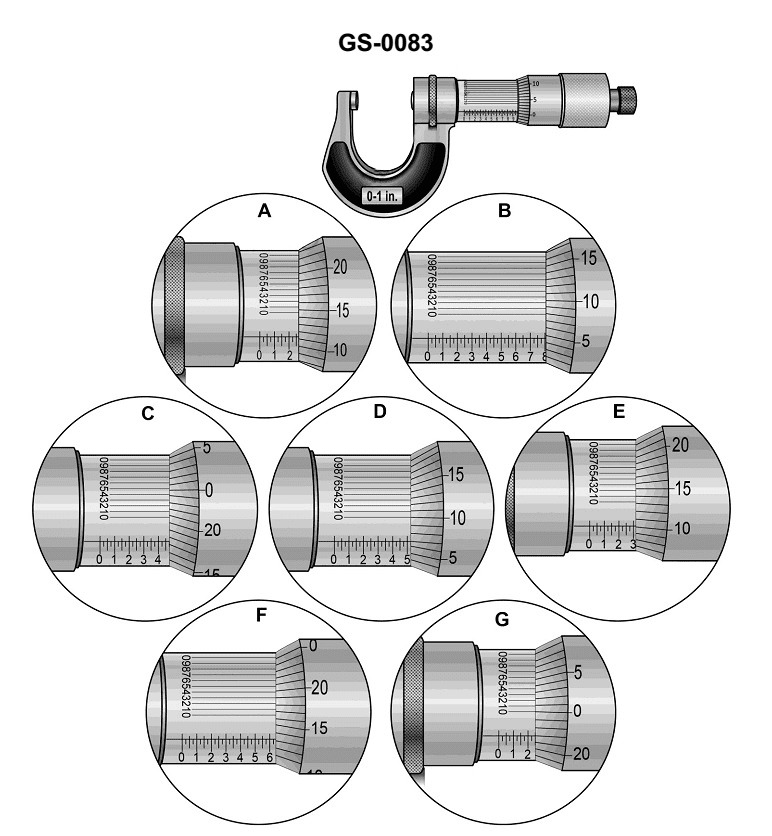
Question 497
Question: What is the reading of the vernier micrometer caliper scale shown in figure "G" in the illustration? Illustration GS-0083
A. 0.2280 inch
B. 0.2340 inch
C. 0.2470 inch
D. 0.2520 inch
The correct answer is C) 0.2470 inch. To determine the correct reading of the vernier micrometer caliper scale, you need to read the main scale and the vernier scale. The main scale shows the whole number of inches, while the vernier scale indicates the decimal portion. In the illustration, the main scale shows 0.24 inch, and the vernier scale aligns with the 47th division, indicating a reading of 0.2470 inch. The other options are incorrect because they do not accurately reflect the reading shown in the illustration. Option A (0.2280 inch) and Option B (0.2340 inch) are too low, while Option D (0.2520 inch) is too high.
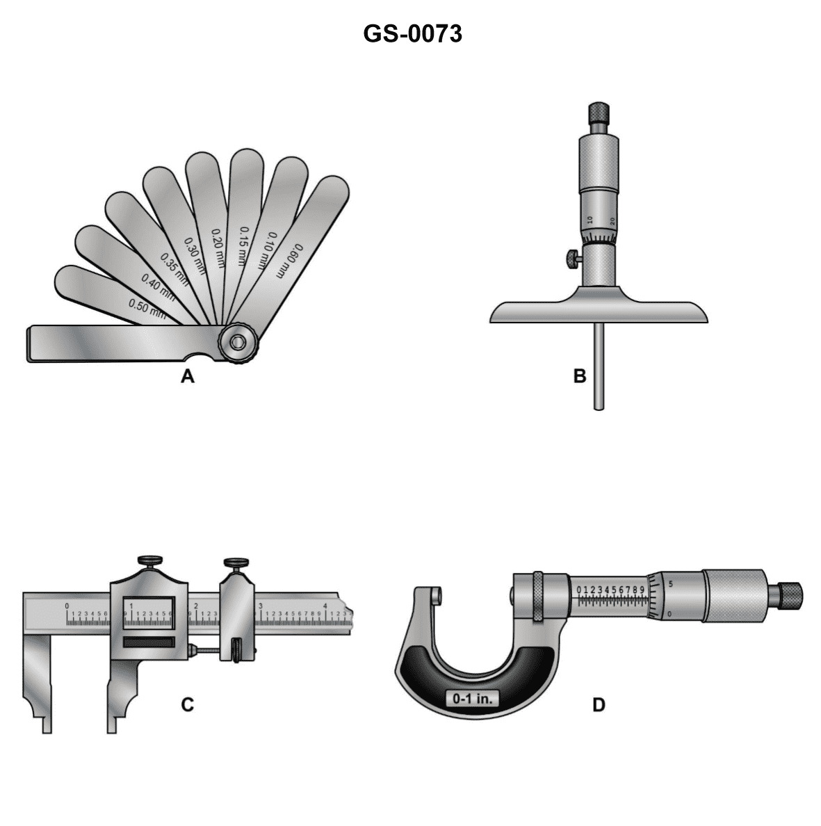
Question 504
Question: Which of the devices shown in the illustration should be used with a bridge gage? Illustration GS-0073
A. A
B. B
C. C
D. D
The correct answer is A. A bridge gage should be used with a depth sounder, which is represented by device A in the illustration GS-0073. The bridge gage is a device used to measure the clearance between the top of the vessel and the underside of a bridge or other overhead obstruction. This is an important safety measure to ensure the vessel can safely pass under without colliding with the overhead structure. The other devices shown, B (compass), C (speedometer), and D (radar), are not directly related to measuring the clearance beneath a bridge and would not be used in conjunction with a bridge gage.
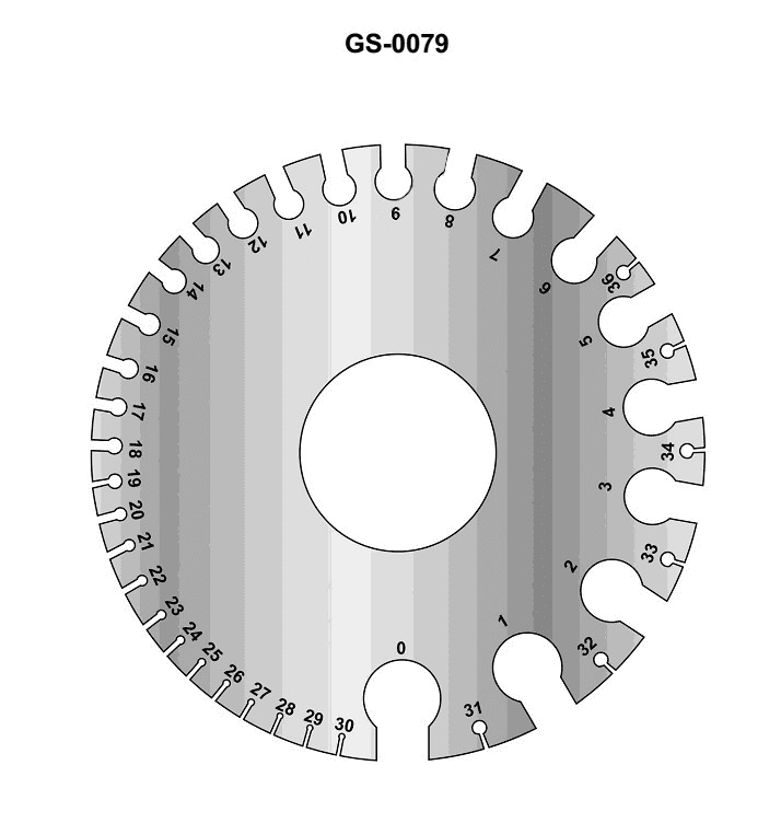
Question 505
Question: The purpose of the instrument illustrated is to _______________. Illustration GS-0079
A. strip insulation from wire
B. gage resistors
C. measure wire diameter
D. measure insulation thickness
The correct answer is C) measure wire diameter. The illustration GS-0079 appears to show a micrometer, which is a precision instrument used to measure the diameter or thickness of objects, including wire. Micrometers are a common tool used in the maritime industry, including by the US Coast Guard, to accurately measure wire and cable dimensions as part of maintenance, repair, and safety inspections. The other answer choices are incorrect because: A) stripping insulation is done with a wire stripper, not a micrometer; B) gaging resistors is not a common application of a micrometer; and D) measuring insulation thickness is not the primary purpose of the micrometer shown in the illustration.
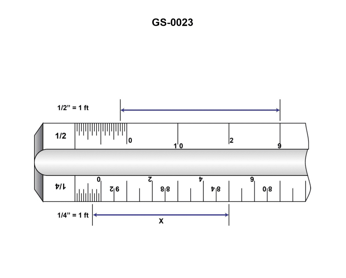
Question 506
Question: The ruler indicated in the illustration is commonly referred to as a/an _______________. Illustration GS-0023
A. Metric Scale
B. Engineers Scale
C. Architects Scale
D. Micrometer Scale
The correct answer is B) Engineers Scale. The illustration GS-0023 is likely depicting a navigation-related instrument, and the ruler shown is commonly referred to as an "engineers scale" in the context of nautical charts and navigation. Engineers scales are divided into different increments, typically in fractional or decimal units, which are used to measure distances and dimensions on engineering drawings and nautical charts. This makes the engineers scale the most appropriate choice for the type of illustration provided. The other options are incorrect because a metric scale is based on the metric system, an architects scale is used in architectural drawings, and a micrometer scale is used for extremely precise measurements beyond the scope of this illustration.
Question 507
Question: Which of the devices shown in the illustration is designed for both inside and outside measurements? Illustration GS-0073
A. A
B. B
C. C
D. D
The correct answer is C. The device labeled C in the illustration GS-0073 is designed for both inside and outside measurements. This type of instrument, commonly known as a caliper, can be used to accurately measure the dimensions of objects both externally and internally. Calipers have jaws that can extend to take inside measurements as well as a depth rod that can be used for depth measurements. The other devices shown, A, B, and D, are specialized for different types of measurements, but do not have the dual inside/outside capability of the caliper.
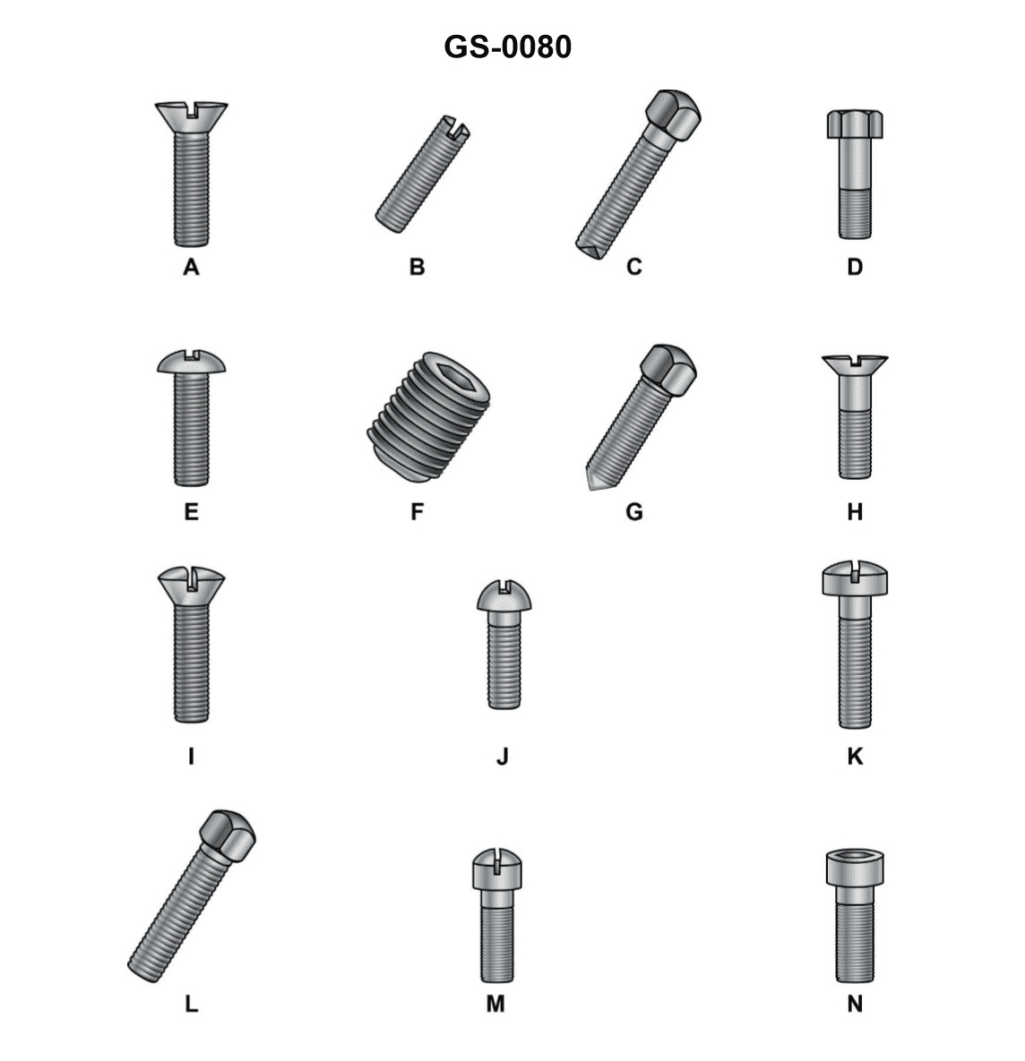
Question 510
Question: Which of the figures in illustration GS-0080 would be used in conjunction with figure "B" of the device shown in illustration GS-0124? Illustrations GS-0080 and GS-0124
A. figure F
B. figure B
C. figure C
D. figure G
The correct answer is A) figure F. According to the Coast Guard regulations, figure F from illustration GS-0080 would be used in conjunction with figure B of the device shown in illustration GS-0124. This is because figure F depicts a compass rose, which is a crucial navigational tool required to be used with the type of device shown in figure B. The other options are incorrect because figure B is the device itself, figure C is not related to navigational tools, and figure G does not depict a compass rose or any other instrument that would be used with the device in figure B.
Question 511
Question: Which of the figures illustrated is not suitable for use as a hex head set screw? Illustration GS-0080
A. figure G
B. figure L
C. figure C
D. figure D
The correct answer is D. The figure labeled D is not suitable for use as a hex head set screw. Hex head set screws are designed to be tightened and loosened using a hex wrench or allen key. The figure D illustration shows a slotted head, which is not compatible with a hex wrench and would not be appropriate for use as a hex head set screw. The other figures (A, C, and L) illustrate hex head designs that would be suitable for use as hex head set screws, as they can be properly engaged and tightened/loosened with a hex wrench tool.
Question 514
Question: Which of the figures in illustration GS-0080 would be used in conjunction with figure "C" in illustration GS-0015? Illustrations GS-0015 and GS-0080
A. figure A
B. figure F
C. figure K
D. figure D
The correct answer is C) figure K. The question is asking which figure from illustration GS-0080 would be used in conjunction with figure "C" in illustration GS-0015. The key is to understand the purpose and application of the figures in these illustrations, which are related to navigation and vessel handling. Figure "C" in illustration GS-0015 represents a "Moored Vessel". Figure K in illustration GS-0080 depicts a "Boat Under Sail", which would be the appropriate figure to use in conjunction with the moored vessel to demonstrate a navigational scenario or vessel handling situation. The other options (A, B, D) do not directly relate to the specific interaction between a moored vessel and a sailing vessel.
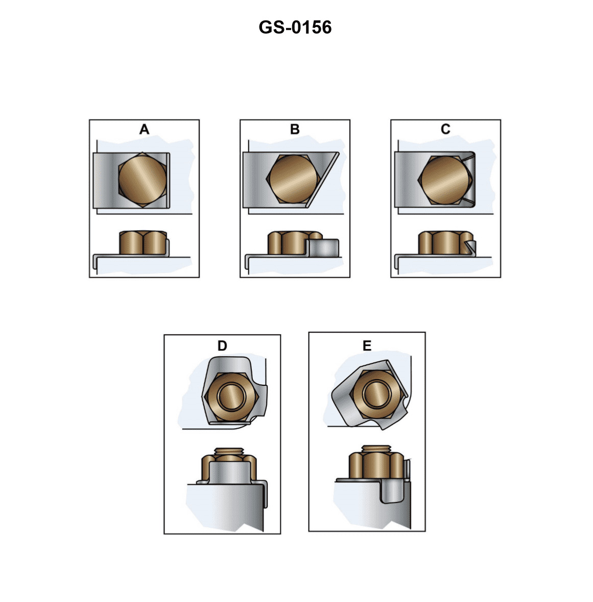
Question 517
Question: Which figure shown in the illustration, is the nut lock improperly used? Illustration GS-0156
A. "A"
B. "B"
C. "C" and "D"
D. "C" and "E"
The correct answer is D) "C" and "E". The nut lock is being improperly used in figures "C" and "E" of the illustration GS-0156. The nut lock is designed to prevent the nut from loosening, but it must be properly installed with the split end of the lock oriented in the direction of the nut's tightening rotation. In figures "C" and "E", the nut lock is installed incorrectly, with the split end oriented in the opposite direction, which would not effectively prevent the nut from loosening. The other answer choices are incorrect because "A" shows the nut lock properly installed, and "B" does not depict a nut lock at all.
Question 518
Question: The locking plates shown in the illustration are used in many marine applications. Which figure indicates the improper method for using these devices? Illustration GS-0156
A. "A"
B. "B"
C. "C"
D. "D"
The correct answer is C. The illustration GS-0156 shows the proper and improper methods for using locking plates in marine applications. Option C indicates the improper method, where the locking plate is not fully engaged and secured. This could lead to the locking plate becoming dislodged, potentially causing a dangerous situation. The other options (A, B, and D) demonstrate the proper installation and use of the locking plates, ensuring they are fully engaged and secured.
Question 519
Question: Which of the figures illustrated would be LEAST desirable for use as a set screw? Illustration GS-0080
A. figure A
B. figure F
C. figure G
D. figure L
The correct answer is A. Figure A would be the least desirable for use as a set screw because it has a flat head, which provides the least amount of gripping surface area compared to the other options. Set screws are typically designed with a pointed or tapered end to allow them to grip the mating component more securely. Figures F, G, and L all have more desirable pointed or tapered head designs that would provide better grip and holding power compared to the flat head of figure A.
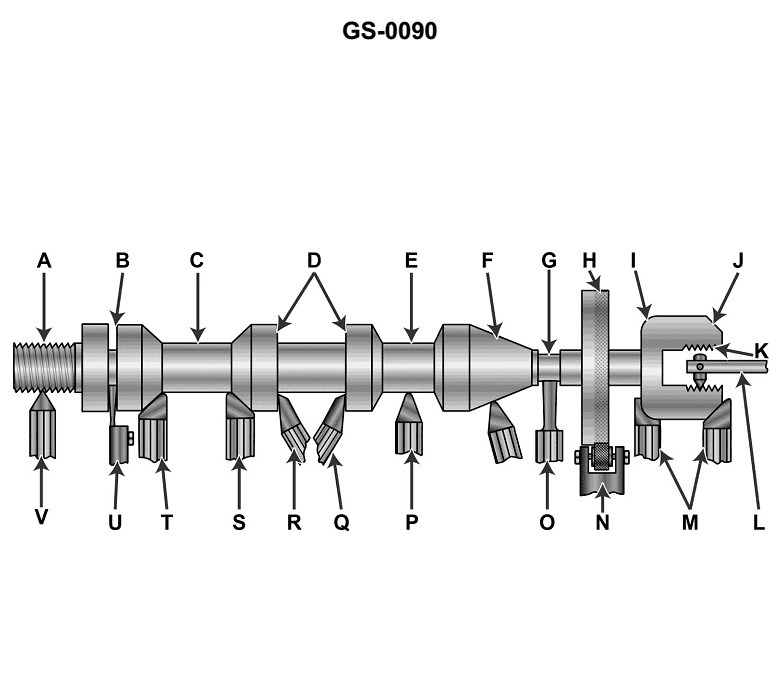
Question 630
Question: The lathe tool shown as figure "N" in the illustration is commonly known as a/an _______________. Illustration GS-0090
A. furling tool
B. curling tool
C. hurling tool
D. knurling tool
The correct answer is D) knurling tool. A knurling tool is a lathe attachment used to create a textured surface on a workpiece, often to improve grip or provide a decorative pattern. This type of tool is commonly used in machinery and metalworking applications, including on items like firearm components, knobs, and handles. The illustration GS-0090 likely depicts a knurling tool, making D the correct choice. The other answer options do not accurately describe the tool shown in the illustration. "Furling," "curling," and "hurling" are not standard terms used to refer to this type of lathe tool.

Question 631
Question: Which of the illustrated lathe tools would be used to produce a smooth finish cut for figure I? Illustration GS-0009
A. A
B. F
C. G
D. D
The correct answer is A. A smooth finish cut for figure I would be produced using a tool labeled "A" in the illustration. This type of tool, known as a finishing cut tool or a smooth cut tool, is specifically designed to create a very smooth surface finish on a workpiece. It has a rounded, gentle cutting edge that allows it to remove material with minimal chatter or tool marks, resulting in a polished, high-quality surface. The other options, such as tools F, G, and D, are better suited for different types of cutting operations, such as roughing, threading, or grooving, and would not be the optimal choice for achieving the desired smooth finish on the workpiece.
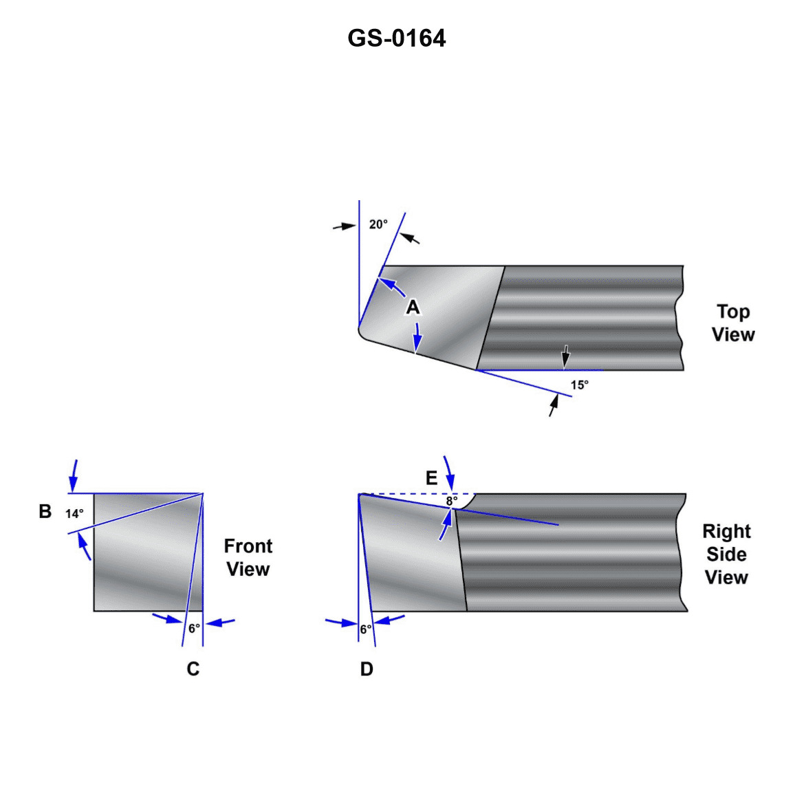
Question 632
Question: The angle "A" shown on the illustrated lathe tool bit is properly called the _______________. Illustration GS-0164
A. side relief angle
B. side rake angle
C. working relief angle
D. nose angle
The correct answer is D) nose angle. The nose angle is the angle formed between the tool bit's cutting edge and a line perpendicular to the workpiece surface. This angle is an important factor in the tool's cutting performance and is a key characteristic of the tool bit geometry. The other answer choices are not correct in this context. The side relief angle, side rake angle, and working relief angle are other geometric angles of the tool bit, but they do not specifically describe the angle labeled "A" in the illustration.
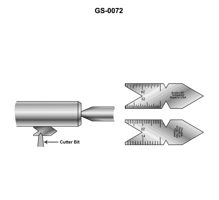
Question 633
Question: The tool shown in the illustration is called a _______________. Illustration GS-0072
A. center gage
B. crotch center
C. drill gage
D. thread gage
The correct answer is A) center gage. A center gage is a tool used to measure the depth of holes or other cavities. It consists of a graduated scale and a pointed tip that can be inserted into the hole to determine its depth. This type of measurement tool is commonly used in various marine engineering and maintenance tasks, including those related to U.S. Coast Guard licensing examinations. The other options are incorrect because: B) crotch center is not a standard tool name, C) drill gage is a tool used to measure drill bit sizes, and D) thread gage is a tool used to measure the size and pitch of screw threads, none of which match the description of the tool shown in the illustration.
Question 634
Question: Which lathe tool shown in the illustration would best be used on a work piece to perform a right hand facing operation? Illustration GS-0090
A. P
B. Q
C. R
D. V
The correct answer is C) R. The tool labeled "R" in the illustration GS-0090 would be the best choice for performing a right-hand facing operation on a workpiece. This is because a right-hand facing operation requires a tool with a cutting edge that is angled or swept to the right, which the "R" tool is designed to provide. The other tool options (P, Q, and V) are not specifically suited for right-hand facing operations.
Question 636
Question: The lathe tools shown as figure "M" in the illustration are commonly known as _______________. Illustration GS-0090
A. form tools
B. curvature cutting tools
C. parting tools
D. universal turning tools
The correct answer is A) form tools. Form tools, also known as profile tools, are used to create specific shapes or contours on a workpiece. They have a predetermined shape that matches the desired profile to be cut. This makes them well-suited for the application shown in the illustration GS-0090, where specific forms or curvatures need to be produced on the lathe. The other options are incorrect because: B) curvature cutting tools is not a standard term, C) parting tools are used to separate or cut off parts of the workpiece, and D) universal turning tools refer to general-purpose tools, not specifically shaped ones.
Question 637
Question: Which of the illustrated figures represents the use of a right hand roughing tool? Illustration GS-0090
A. Figure P
B. Figure S
C. Figure T
D. Figure V
The correct answer is C) Figure T. The use of a right-hand roughing tool is represented by Figure T in the illustrated figures. This is because a right-hand roughing tool is typically used to remove material from the workpiece in a clockwise direction, which is the orientation depicted in Figure T. The other answer choices, Figures P, S, and V, do not represent the use of a right-hand roughing tool, as they show different tool orientations or tool types.
Question 638
Question: The lathe tool shown as figure "U" in the illustration is commonly known as a/an _______________. Illustration GS-0090
A. universal turning tool
B. right side end facing tool
C. left cut side-facing tool
D. cutting-off tool
The correct answer is D) cutting-off tool. A cutting-off tool, also known as a parting tool, is used to separate or cut off a workpiece from the main stock. This is the primary function of the tool shown as figure "U" in the illustration GS-0090. The other answer choices do not accurately describe the purpose and use of this specific lathe tool. The right side end facing tool (B) is used for facing operations, while the left cut side-facing tool (C) is used for side-facing operations. The universal turning tool (A) is a general-purpose tool used for various turning operations, but it is not specifically designed for cutting off the workpiece.
Question 639
Question: Which single illustrated lathe tool could be used to turn down the stock in figure II? Illustration GS-0009
A. A
B. B
C. C
D. G
The correct answer is B. The illustration GS-0009 shows various lathe tools, and tool B is the correct choice to turn down the stock in figure II. This tool is a lathe cutting tool, specifically a single-point tool, which is commonly used for general purpose turning operations on a lathe. The other options, A, C, and G, represent different types of lathe tools that are not best suited for the task of turning down the stock as depicted in figure II.
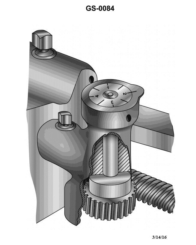
Question 647
Question: To properly cut even numbered threads using the lathe thread dial indicator shown in the illustration, you should close the lathe split or half-nut on_______________ Illustration GS-0084
A. even numbered lines only
B. odd numbered lines only
C. any line on the dial
D. any unnumbered half line
The correct answer is C) any line on the dial. To properly cut even numbered threads using the lathe thread dial indicator, the user should close the lathe split or half-nut on any line on the dial, regardless of whether the line is numbered or not. This is because the thread dial indicator is designed to allow the user to engage the half-nut at any position on the dial, and the even numbered threads will be cut correctly regardless of which line is used. The other options are incorrect because A) closing the half-nut on even numbered lines only would not work, as the thread cutting process requires engaging the half-nut at any line, and B) and D) are too restrictive, as the half-nut can be engaged on any line, not just odd numbered or unnumbered lines.
Question 649
Question: All straight shank twist drills must be mounted or held in a _______________.
A. tapered sleeve
B. morse sleeve
C. drill chuck
D. drill socket
The correct answer is C) drill chuck. All straight shank twist drills must be mounted or held in a drill chuck. This is because a drill chuck provides a secure and accurate method of holding the straight shank of a twist drill, allowing it to be used in a drill press or other power tool. The other options, such as a tapered sleeve (A), morse sleeve (B), or drill socket (D), are not suitable for holding straight shank twist drills, as they are designed for different types of tooling or attachments.
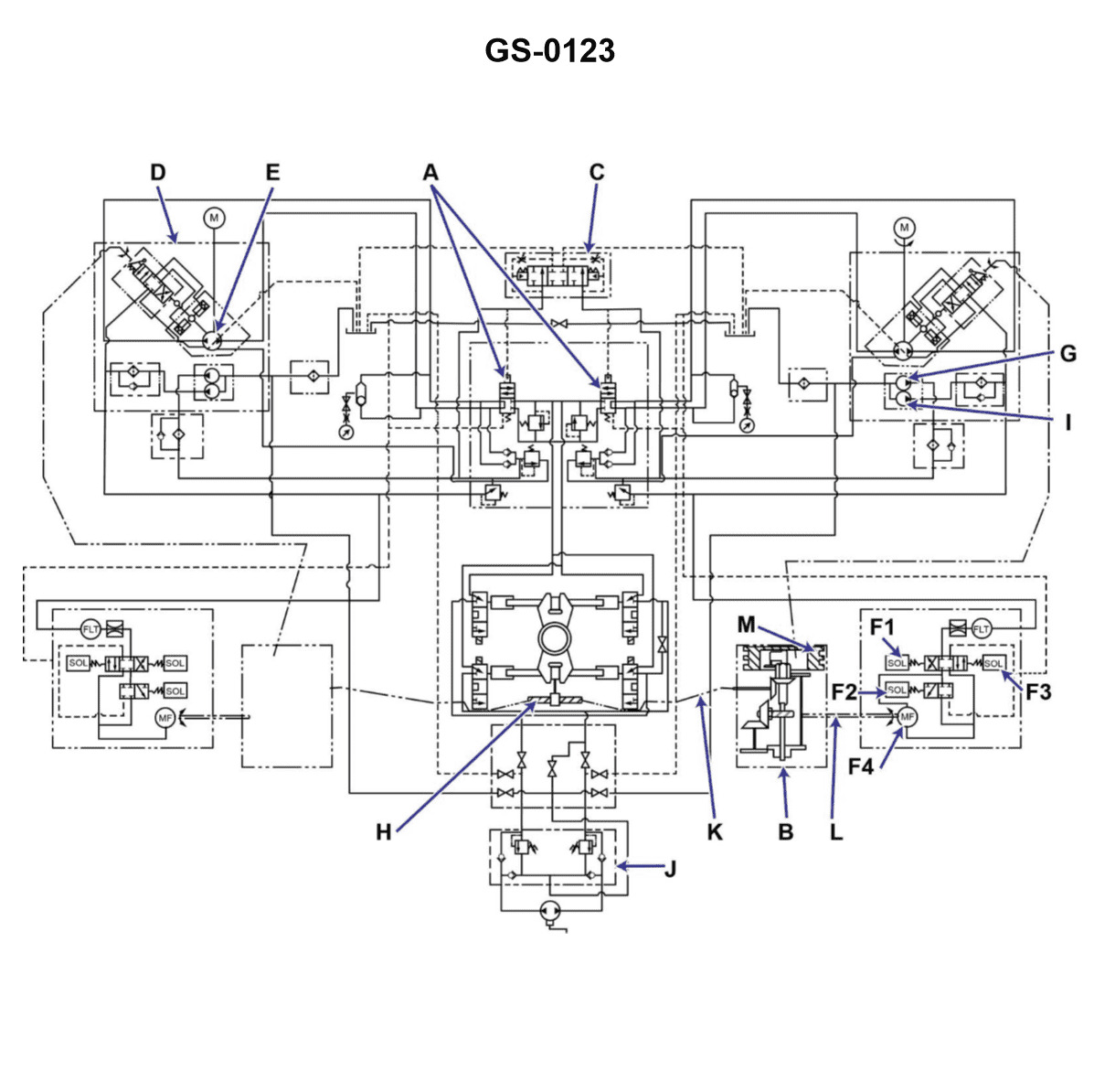
Question 660
Question: A command signal input to the steering gear has initiated rudder movement for 20° right rudder. The follow-up mechanism at the beginning of the rudder movement will _______________. Illustration GS-0123
A. be in motion with a null input
B. be in motion providing an input to place the variable stroke pump at null stroke
C. be in motion providing an input to place the variable stroke pump on maximum stroke
D. not be in motion, thus a null input
The correct answer is A) be in motion with a null input. When a command signal initiates 20° of right rudder movement, the follow-up mechanism at the beginning of the rudder movement will be in motion to detect and respond to the change in rudder position. However, since the rudder has not yet reached the commanded 20° position, the follow-up mechanism will have a null input, meaning it is not providing any input to the variable stroke pump or other steering gear components. The other answer choices are incorrect because B) and C) describe the follow-up mechanism providing an input to the variable stroke pump, which would only occur once the rudder has reached the commanded position, not at the beginning of the movement. D) is incorrect because the follow-up mechanism is designed to be in motion to detect and respond to changes in rudder position.
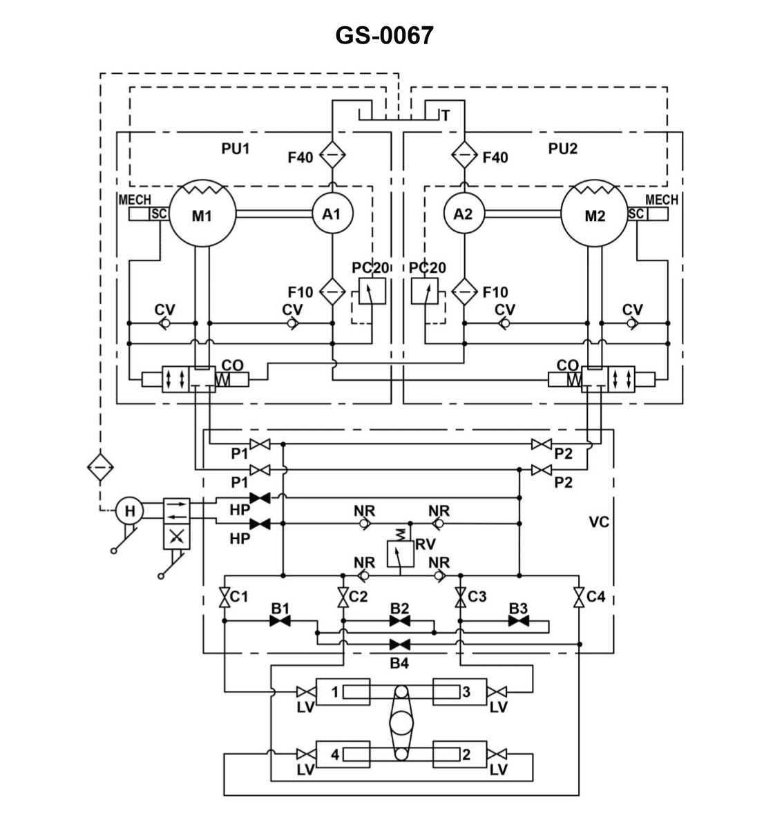
Question 664
Question: The rudder torque capacity of the four ram steering gear illustrated is rated at 44,210,000 inch-pounds with one power unit in operation. If the four ram system was able to be operated as a two ram system with both power units on line, what would be the available torque? Illustration GS-0067
A. 11,052,500 inch-pounds
B. 22,105,000 inch-pounds
C. 44,210,000 inch-pounds
D. 88,420,000 inch-pounds
The correct answer is B) 22,105,000 inch-pounds. The rationale is that with a four ram steering gear system, the torque capacity is rated at 44,210,000 inch-pounds with one power unit in operation. If the system is operated as a two ram system with both power units online, the available torque would be half of the original four ram system, which is 44,210,000 / 2 = 22,105,000 inch-pounds. The other options are incorrect because: A) 11,052,500 inch-pounds is only half of the correct answer. C) 44,210,000 inch-pounds is the rating for the four ram system, not the two ram system. D) 88,420,000 inch-pounds is double the correct answer and would not be the available torque for a two ram system.
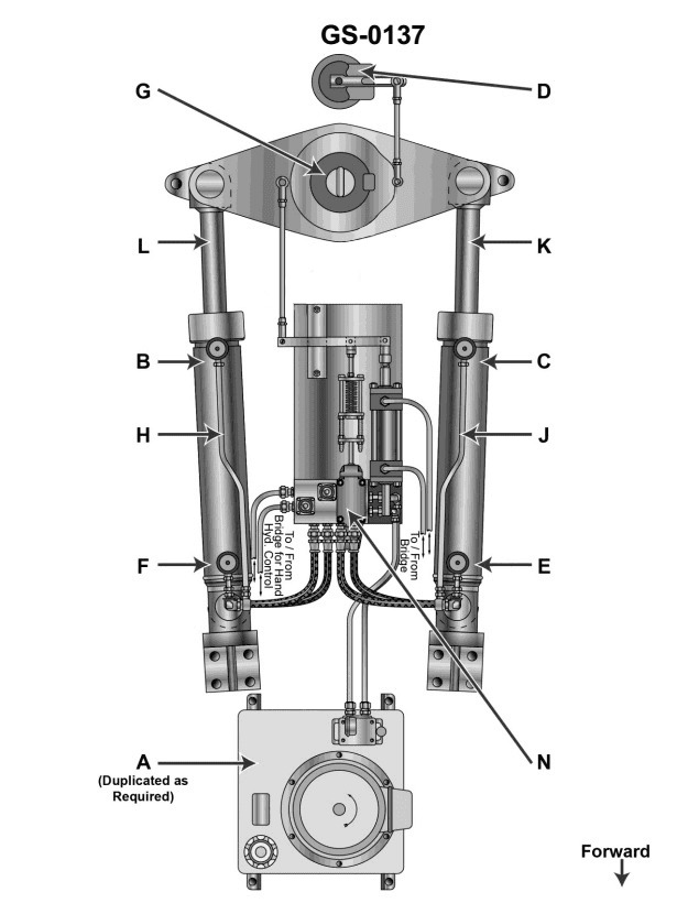
Question 665
Question: When responding to a 'right rudder' command from the amidships position, which parts of the steering gear system illustrated will be subjected to the highest pressure? Illustration GS-0137
A. "C" and "F"
B. "E" and "B"
C. "F" and "E"
D. "B" and "C"
The correct answer is B) "E" and "B". When responding to a 'right rudder' command from the amidships position, the components of the steering gear system that will be subjected to the highest pressure are the ram cylinder (E) and the pump (B). This is because the right rudder command requires the hydraulic steering system to apply force to the right side of the rudder, which in turn creates higher pressure in the ram cylinder and the pump that supplies the hydraulic fluid. The other answer choices are incorrect because they do not accurately identify the components that would experience the highest pressure during a right rudder command. For example, options A and D incorrectly identify the components as "C" and "F", which are not the primary pressure-bearing components in this scenario.
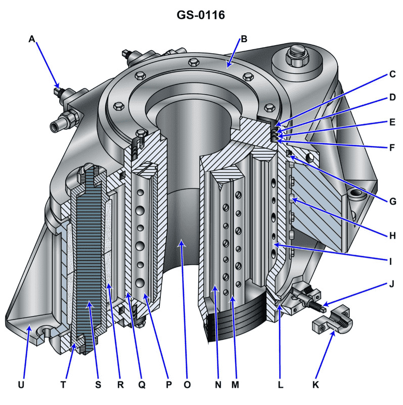
Question 667
Question: The device shown in the illustration is a/an _______________. Illustration GS-0116
A. vane type steering gear
B. oil scraper ring stuffing box for a crosshead engine
C. diesel engine motor mount
D. mechanical shaft seal
The correct answer is A) vane type steering gear. The illustration GS-0116 depicts a vane type steering gear, which is a type of steering mechanism commonly used on vessels. The vanes or blades within the steering gear unit convert the rotational motion of the steering wheel into a force that moves the rudder, allowing the operator to steer the vessel. The other answer choices are incorrect because: B) is describing a component of a crosshead engine, not a steering gear. C) is describing a mount for a diesel engine, not a steering gear. D) is describing a mechanical shaft seal, not a steering gear.
Question 668
Question: If it is necessary to prevent the rudder from moving while a repair is made on the steering system using the illustrated actuator _______________. Illustration GS-0116
A. secure the valves in the supply and return lines
B. screw in the locking pin, item "J"
C. tighten the locking pins, item "H" at each position of item "I" to keep the rudder from swinging
D. tighten the locking screws in item "S"
The correct answer is A) secure the valves in the supply and return lines. To prevent the rudder from moving while making a repair on the steering system, the appropriate action is to secure the valves in the supply and return lines. This effectively isolates the actuator from the hydraulic system, preventing any inadvertent movement of the rudder. The other options, while potentially relevant in other situations, do not directly address the need to isolate the actuator and prevent rudder movement in this specific scenario.
Question 669
Question: If oil under pressure is supplied to the area noted as "N" on the vane in the illustration _______________. Illustration GS-0116
A. "O" will be hydraulically locked in place even though oil is returned to the main pump from the area between "M" and "I"
B. "O" will rotate clockwise as oil is returned from the area between "M" and "I"
C. "O" will rotate counter-clockwise as oil is returned from the area between "M" and "I"
D. "Q" will rotate counter-clockwise as oil is returned from the area between "M" and "I"
The correct answer is C) "O" will rotate counter-clockwise as oil is returned from the area between "M" and "I". When oil under pressure is supplied to the area noted as "N" on the vane, it will cause the vane labeled "O" to rotate counter-clockwise. This is because the oil pressure in the area between "M" and "I" will be lower, allowing the vane to rotate in that direction as the oil is returned from that area. The other options are incorrect because: A) "O" will not be hydraulically locked in place, as the oil pressure differential will cause it to rotate counter-clockwise. B) "O" will not rotate clockwise, as the oil pressure differential will cause it to rotate counter-clockwise. D) "Q" will not rotate counter-clockwise, as the question specifically states that the rotation will affect the vane labeled "O".
Question 670
Question: The operation of the device shown in the illustration is dependent upon _______________. Illustration GS-0116
A. all items, similar to "I" move as the rudder stock rotates
B. all items, similar to "N" move as the rudder stock rotates
C. both "I" and "N" move as the rudder stock rotates
D. neither "I" nor "N" move as the rudder stock rotates
The correct answer is B) all items, similar to "N" move as the rudder stock rotates. The operation of the device shown in the illustration is dependent upon the movement of the items labeled "N" as the rudder stock rotates. This is because the "N" items are directly connected to and move with the rotating rudder stock, which is the primary mechanism that controls the device's operation. The other answer choices are incorrect because A) is false as the "I" items do not move with the rudder stock, C) is false as only the "N" items move, and D) is false as the "N" items do move with the rudder stock.