Pass Your Coast Guard Licensing Exams!
Study offline, track your progress, and simulate real exams with the Coast Guard Exams app
General Subjects - 1st Asst/Chief
41 images
Question 17
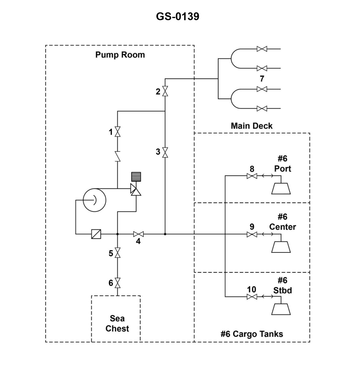
Question: Salt water ballast is to be discharged into the No.6 port and starboard wing tanks. Which combination of valves illustrated, must be opened, and which valves should be closed? Illustration GS-0139
A. 1, 2, 5 and 6 open; 4, 7, 8 and 9 closed.
B. 1, 2, 7 and 9 open; 3, 4, 5, 6, 8 and 10 closed.
C. 1, 3, 5, 6, 8 and 10 open; 2, 4, 7 and 9 closed.
D. 3, 4, 7 and 9 open; 1, 2, 5, 6 and 10 closed.
The correct answer is C) 1, 3, 5, 6, 8 and 10 open; 2, 4, 7 and 9 closed. To discharge salt water ballast into the No.6 port and starboard wing tanks, the valves that need to be opened are 1, 3, 5, 6, 8 and 10. This allows the ballast water to flow into the designated tanks. The valves that should be closed are 2, 4, 7 and 9 to prevent the water from going into the wrong tanks or areas. The other options are incorrect because they either have the wrong valves open or closed, which would not allow the ballast water to be discharged properly into the No.6 port and starboard wing tanks.
Question 18
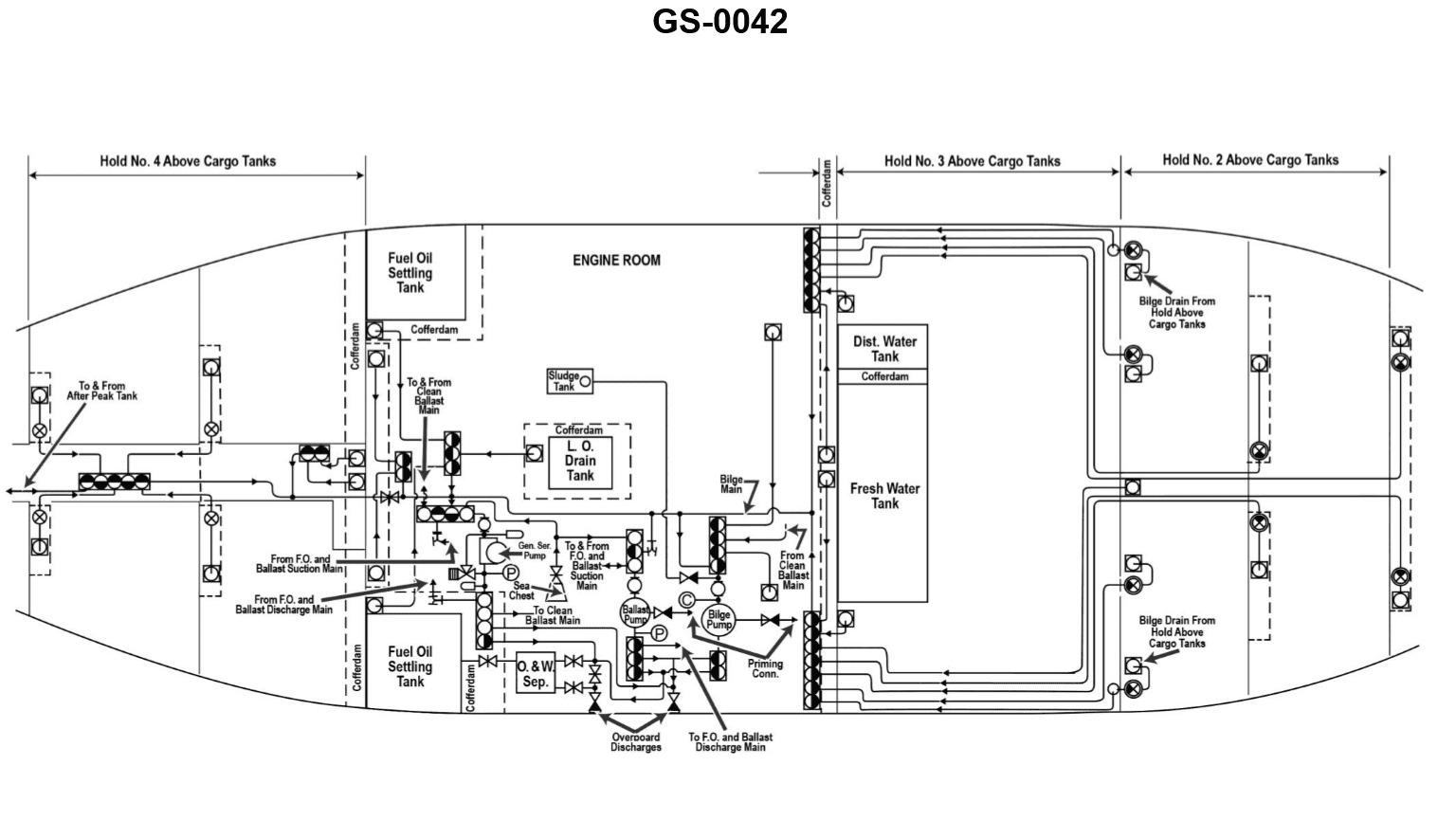
Question: In order to take suction on the lube oil drain tank cofferdam with the bilge pump shown in the illustration, how many suction side valves must be open? Illustration GS-0042
A. One
B. Two
C. Three
D. Four
The correct answer is B) Two. To take suction on the lube oil drain tank cofferdam, two suction side valves must be open. This is because the bilge pump requires two open valves to draw liquid from the cofferdam - one valve to allow the liquid to enter the suction side of the pump, and another valve to allow the liquid to be discharged from the pump. The other answer choices are incorrect because one valve is not enough to allow the liquid to flow into and out of the pump (A), three valves would be unnecessarily complex (C), and four valves would be an excessive number for this simple suction operation (D).
Question 33
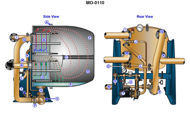
Question: Item "M" shown in the illustration is the _______________. Illustration MO-0110
A. salt water inlet
B. brine water outlet
C. feed water inlet
D. jacket water inlet
The correct answer is D) jacket water inlet. The jacket water inlet is the component that allows water to circulate through the engine's cooling jacket, which helps dissipate the heat generated by the engine. This is a critical part of the engine's cooling system and is essential for proper engine operation. The other options are incorrect because: A) A salt water inlet would be used to draw seawater for cooling purposes, which is not the function of the component shown. B) A brine water outlet would be used to expel spent cooling water, which is also not the function of the component shown. C) A feed water inlet would be used to supply water for the boiler or other steam-powered systems, which is not relevant in this context.
Question 34
Question: Which of the following is NOT a function of the water supply through item "P" shown in the illustration? Illustration MO-0110
A. It supplies feed water to evaporator.
B. It supplies the operating medium used in the removal of the distillate.
C. It supplies the operating medium used in the removal of the brine.
D. It supplies the operating medium used in the removal of air and non-condensable gases.
The correct answer is B) It supplies the operating medium used in the removal of the distillate. The water supply through item "P" in the illustration is typically used to supply feed water to the evaporator, to supply the operating medium used in the removal of brine, and to supply the operating medium used in the removal of air and non-condensable gases. However, it does not supply the operating medium used in the removal of the distillate, as that function is typically performed by a separate system. The other answer choices (A, C, and D) are incorrect because they do describe functions of the water supply through item "P" in the illustration.
Question 35
Question: What is the function of item 'D' shown in the illustration? Illustration MO-0110
A. It heats the entering feed water.
B. It condenses the distillate.
C. It heats the jacket water entering the device.
D. It causes the jacket water to evaporate.
The correct answer is A) It heats the entering feed water. The illustration MO-0110 is likely depicting a marine distillation unit, which is used to produce fresh water from seawater on ships. In such a system, the function of item 'D' is to heat the incoming feed water (seawater) prior to it entering the distillation chamber. This pre-heating helps improve the efficiency of the distillation process by increasing the temperature of the feed water. The other answer choices are incorrect because they do not accurately describe the function of item 'D' in a typical marine distillation unit. Option B refers to the condenser, option C refers to the jacket water, and option D does not accurately describe the role of item 'D' in the system.
Question 36
Question: What is the function of device "A" shown in the illustration? Illustration MO-0110
A. It aids in removing condenser tube bundles.
B. It provides a conduit for incoming feed water.
C. It is only used as a lifting beam during installation.
D. It serves as a hinge for ease of opening the shell.
The correct answer is D) It serves as a hinge for ease of opening the shell. The illustration MO-0110 likely depicts a component of a boiler or other pressurized vessel. The device labeled "A" is a hinge that allows the shell or casing of the vessel to be opened for inspection, maintenance, or repair. This hinged design provides easy access to the internal components while maintaining the structural integrity of the vessel. The other answer choices are incorrect because: A) removing condenser tubes is not the function of this device, B) it does not provide a conduit for feed water, and C) it is not solely used as a lifting beam during installation.
Question 37
Question: Which of the following conditions occurs in the section labeled "F" of the device shown in the illustration? Illustration MO-0110
A. The vapors produced in section "G" are condensed and the non-condensable gases are removed.
B. The jacket water flowing through device "I" is heated.
C. The sea water flowing through device "I" is cooled.
D. Non-condensable vapors are removed and water vapors are preheated.
The correct answer is A) The vapors produced in section "G" are condensed and the non-condensable gases are removed. This is correct because in the section labeled "F" of the device shown in the illustration, the purpose is to condense the vapors produced in the previous section and remove any non-condensable gases. This process is essential for the proper operation and efficiency of the overall system. The other options are incorrect because they do not accurately describe the function of section "F". Option B and C refer to the operation of a different component, "I", which is not the focus of the question. Option D describes a different process that occurs elsewhere in the system, not specifically in section "F".
Question 50
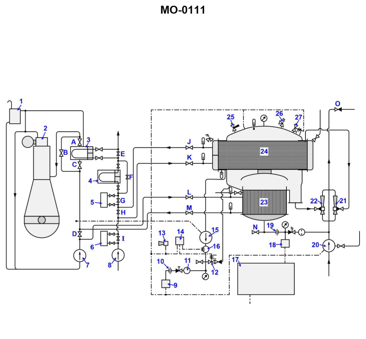
Question: What is the function of the item "7" shown in the illustration? Illustration MO-0111
A. This jacket water pump circulates salt water through the jacket water cooling system to provide engine cooling.
B. This jacket water pump circulates fresh water throughout the engine cooling and distiller heating systems.
C. This jacket water pump supplies the distiller with sea water feed while also powering the eductors.
D. This circulating salt water pump will supply feed water for the operation of the distiller.
The correct answer is B) This jacket water pump circulates fresh water throughout the engine cooling and distiller heating systems. The jacket water pump (item "7" in the illustration) is responsible for circulating fresh water through the engine's cooling system and the distiller's heating system. This allows the engine to be cooled effectively and provides the necessary thermal energy to the distiller for its operation. The other answer choices do not accurately describe the function of this particular pump.
Question 51
Question: Excess brine accumulated in the distiller, shown in the illustration, is removed during normal operation by _______________. Illustration MO-0111
A. orifice "19" regulating the amount of feed water entering the distiller, thereby preventing excess brine accumulation
B. opening the drain valve located to the left of orifice "19"
C. the hydrokineter labeled "21"
D. the continuous action of ejector "22"
The correct answer is D) the continuous action of ejector "22". The illustration shows a distiller system, and in a distiller, excess brine is continuously removed by the action of the ejector labeled "22". The ejector uses the suction created by the flow of steam or air to draw out the excess brine, preventing it from accumulating in the distiller. This is a normal part of the distiller's operation and is the primary means of removing excess brine. The other options are incorrect because: A) the orifice "19" regulates the feed water, not the brine removal; B) there is no drain valve shown to the left of orifice "19"; and C) the hydrokineter "21" is not involved in the brine removal process.
Question 52
Question: During operation which device listed removes air and non-condensable gases from the unit shown in the illustration? Illustration MO-0111
A. "21"
B. "22"
C. "25"
D. "27"
The correct answer is A) "21". The device labeled "21" in the illustration MO-0111 is the air vent or air release valve. This component is responsible for removing air and non-condensable gases from the unit shown, which is typically a steam or hot water system. The air vent allows the system to operate more efficiently by preventing air pockets and ensuring proper circulation of the working fluid. The other options are incorrect because they represent different components of the system, such as the pressure gauge (22), the steam trap (25), and the return line (27), which do not specifically remove air and non-condensable gases.
Question 53
Question: Which of the following statements represents the two major functions provided by the item labeled "20" shown in the illustration? Illustration MO-0111
A. The pump supplies the motive force to the ejectors and removes the excess distillate.
B. The pump is used to drain the shell when the unit is secured, in addition to powering the ejectors.
C. The pump provides for venting of associated equipment while also powering the ejectors.
D. The pump supplies the motive fluid to the ejectors in addition to supplying the feed water to the distiller.
The correct answer is D: The pump supplies the motive fluid to the ejectors in addition to supplying the feed water to the distiller. This is correct because the pump labeled "20" in the illustration is responsible for two key functions - providing the motive force to power the ejectors, and supplying the feed water to the distillation unit. The pump is a critical component that enables the overall desalination system to operate effectively. The other answer choices are incorrect because they do not fully capture the dual roles of the pump. Option A describes only one function, option B mentions draining the shell but not powering the ejectors, and option C refers to venting rather than supplying feed water.
Question 54
Question: Which device is used to prevent over pressurization of the illustrated distiller? Illustration MO-0111
A. "12"
B. "13"
C. "19"
D. "26"
The correct answer is D) "26". The device used to prevent over pressurization of the illustrated distiller is a pressure relief valve, which is typically labeled as item "26" in the diagram. Pressure relief valves are required by regulations to be installed on distillation systems to protect against excessive pressure buildup, which could be hazardous. The other options, "12", "13", and "19", do not serve this specific function of preventing over pressurization.
Question 55
Question: Which of the following statements concerning the systems shown in the illustration is correct? Illustration MO-0111
A. The jacket water primarily loses its heat at the cooler and is further heated in the evaporator section.
B. The feed water gains heat in section "23", while the vapor gives up heat in section "24".
C. The jacket water absorbs heat in the evaporator section, while giving up its heat in the distiller section.
D. The feed water acquires heat passing through devices "2"and "23".
The correct answer is B) The feed water gains heat in section "23", while the vapor gives up heat in section "24". This is correct because in a typical steam distillation system, the feed water (untreated water) enters the system and passes through a heat exchanger (section "23") where it gains heat from the outgoing distilled vapor. Meanwhile, the distilled vapor gives up its heat in this heat exchanger (section "24") before being condensed and collected as the final distilled product. The other options are incorrect because they do not accurately describe the heat transfer processes occurring in the system. For example, option A is incorrect as the jacket water does not primarily lose heat at the cooler, and option C is incorrect as the jacket water absorbs heat in the distiller section, not the evaporator section.
Question 56
Question: Which of the valve arrangements listed would be correct for operating the distillation plant shown in the illustration? Illustration MO-0111
A. Valves "C", "J", "K", "L", "M" open, valves "A", "B", "D", and "H" closed.
B. Valves "D", "H", "J", "K", "L", "M" open, valves "I", "G", "F", and "E" closed.
C. Valves "H", "J", "K", "L", "M" open, valve "D" closed.
D. Valves "J", "K", "L", "M" open, valves "D" and "H" closed.
The correct answer is D) Valves "J", "K", "L", "M" open, valves "D" and "H" closed. This is the correct answer because this valve arrangement would allow the distillation plant to function properly. Valves "J", "K", "L", and "M" need to be open to allow the distillation process to occur, while valves "D" and "H" need to be closed to prevent any interruptions or leaks in the system. The other answer choices are incorrect because they either have the wrong combination of open and closed valves, or they are missing critical valves that need to be open or closed for the distillation plant to operate correctly.
Question 57
Question: Which of the following statements describes the approximate relation between the feed water entering the unit shown in the illustration and brine being removed? Illustration MO-0111
A. The brine will be removed at a faster rate than feed water entering to prevent the possibility of flooding.
B. Twenty-five percent of the feed water entering the device is removed as brine.
C. Seventy-five percent of the feed water entering the unit is removed as brine.
D. The amount of feed water entering the distiller is dependent upon the condition of device "7", while the amount of brine leaving is dependent upon the condition of device "21".
The correct answer is C) Seventy-five percent of the feed water entering the unit is removed as brine. In a distillation process, the majority of the feed water (typically around 75%) is removed as brine or concentrated waste, while the remaining 25% is collected as purified distillate. This is because the distillation process is designed to concentrate the impurities and minerals in the feed water, leaving the purified water behind. The higher the concentration of dissolved solids in the feed water, the more brine will need to be removed to maintain the efficiency of the distillation unit. The other options are incorrect because: A) The brine is not removed at a faster rate than the feed water entering; the process is designed to maintain a specific ratio of brine removal to feed water input. B) Twenty-five percent of the feed water is not removed as brine; the majority (around 75%) is removed as brine. D) The amount of brine leaving is not dependent on a specific device; it is a function of the overall distillation process design and the concentration of dissolved solids in the feed water.
Question 63
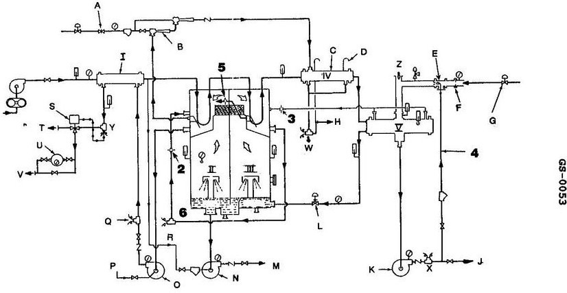
Question: While the illustrated system is operated using the steam supply through "F" the strainer in line "4" becomes fouled, this will result in _______________. Illustration GS-0053
A. pump "K" becoming vapor bound
B. a reduction in distillate production
C. the temperature regulated by "L" difficult to maintain
D. nothing unusual for the type of operation indicated as this line was unnecessary in the installation
The correct answer is B) a reduction in distillate production. The explanation is as follows: 1. Confirm which answer is correct: The correct answer is B) a reduction in distillate production. 2. Explain the reasoning or regulation that makes it correct: If the strainer in line "4" becomes fouled, it will restrict the flow of steam through the system. This will result in a reduction in the amount of distillate produced, as the steam supply to the system will be diminished. 3. Explain why the other options are incorrect: Option A is incorrect because a fouled strainer would not cause the pump "K" to become vapor bound. Option C is incorrect because the temperature regulated by "L" may become difficult to maintain, but this is not the primary effect of the fouled strainer. Option D is incorrect because the strainer in line "4" is a necessary component of the system, and its fouling would have a significant impact on the system's operation. 4. Keep it concise: The explanation provided covers the key points in a clear and concise manner.
Question 66
Question: A high reading is indicated at the salinity cells labeled "Y", "Q", and "6" shown in the illustration. This would be the probable result of _______________. Illustration GS-0053
A. carryover from "III"
B. faulty cells at each location
C. a leak in item "I"
D. erosion of item "2"
The correct answer is A) carryover from "III". The high readings at the salinity cells labeled "Y", "Q", and "6" are likely due to carryover from the component labeled "III". This could indicate an issue with the sealing or separation between the components, allowing saltwater or other conductive material to flow from "III" to the other salinity cells, causing the high readings. The other options are incorrect because: B) faulty cells at each location would not explain the consistent high readings across multiple cells, C) a leak in item "I" would not necessarily impact the salinity cells in that way, and D) erosion of item "2" is not directly relevant to the salinity cell readings.
Question 70
Question: While the illustrated system is operated using the steam supply through "F" the strainer in line "4" becomes fouled, this will result in . Illustration GS-0053
A. a reduction in distillate production
B. the temperature regulated by "L" difficult to maintain
C. nothing unusual for the type of operation indicated as this line was unnecessary in the installation
D. pump "K" becoming vapor bound
The correct answer is A) a reduction in distillate production. When the strainer in line "4" becomes fouled, it will restrict the steam flow to the system, which in turn will reduce the amount of steam available for the distillation process. This will result in a decrease in the production of distillate, as the system will not be able to generate the same amount of steam-powered distillation as it would with a clean strainer. The other options are incorrect because: B) the temperature regulated by "L" may be difficult to maintain, but this is a secondary effect of the reduced steam flow; C) the strainer in line "4" is a necessary component for the proper operation of the system; and D) the pump "K" would not become vapor-bound, as the reduced steam flow would not affect the pump's operation.
Question 72
Question: What would happen if valve "25" shown in the illustration, vibrated open with the unit in operation? Illustration MO-0111
A. The absolute pressure of the unit would increase, causing a decrease in distillate output.
B. The unit would automatically shut down due to the closing of the low pressure contacts.
C. Jacket water would be automatically by-passed around the distiller.
D. The unit would continue to operate with no adverse effects.
The correct answer is A) The absolute pressure of the unit would increase, causing a decrease in distillate output. If valve "25" vibrates open while the unit is in operation, it would allow air to enter the system, increasing the absolute pressure within the distiller. This increased pressure would result in a lower pressure differential across the distiller, leading to a decrease in the distillate output. The other options are incorrect because: B) The unit would not automatically shut down due to low pressure contacts, as the increased pressure would not trigger a low-pressure condition. C) The jacket water would not be automatically bypassed, as this would not be the appropriate response to the increased pressure. D) The unit would not continue to operate without adverse effects, as the decreased distillate output would be an adverse effect.
Question 73
Question: If the wearing rings of device "7" shown in the illustration become worn, how will the evaporation rate in "23" be affected? Illustration MO-0111
A. The rate of evaporation will decrease.
B. Device "7" does not use wearing rings, as these are normally positive displacement pumps.
C. The rate of evaporation is dependent on the level of vacuum maintained within the unit, and not the flow of water to the unit.
D. The rate of evaporation will not be affected as the standby pump; labeled "8" will be used instead.
The correct answer is A) The rate of evaporation will decrease. The wearing rings of device "7" are typically used to maintain proper clearance between the impeller and casing in a centrifugal pump. As these rings wear over time, the pump's efficiency decreases, resulting in a lower flow rate. Since the evaporation rate in device "23" is dependent on the flow of water to the unit, a lower flow rate from the worn pump will lead to a decreased evaporation rate. The other answer choices are incorrect because: B) Device "7" is likely a centrifugal pump that does use wearing rings; C) The evaporation rate is directly affected by the flow of water, not just the vacuum level; and D) The standby pump labeled "8" is not mentioned as being used in this scenario.
Question 74
Question: If valve "D" is opened during the normal operation of the distiller shown in the illustration, which of the events listed will occur? Illustration MO-0111
A. The jacket water cooler will be overloaded, eventually causing a critical engine alarm.
B. The amount of vapor formed in the evaporator will increase.
C. The amount of vapor being formed in the evaporator will decrease.
D. The output of pump "7" will increase with a corresponding increase in pressure.
The correct answer is C) The amount of vapor being formed in the evaporator will decrease. When valve "D" is opened during normal distiller operation, it allows more feed water to enter the evaporator. This additional feed water will dilute the concentrated brine solution, reducing the temperature difference between the brine and the vapor space. As a result, the amount of vapor being generated in the evaporator will decrease. The other options are incorrect because: A) opening valve "D" would not overload the jacket water cooler, B) the amount of vapor would decrease, not increase, and D) the output of pump "7" would not increase as a result of opening valve "D".
Question 75
Question: Which of the conditions listed would indicate a large condenser tube leak within the distiller shown in the illustration? See Illustration MO-0111
A. A slow continuous rise in the lube oil cooler outlet temperature indicated at device "4".
B. The activation of the salinity monitoring equipment's annunciator circuit.
C. A decrease in the level of the main engine expansion tank as indicated by a low level alarm.
D. An increase in distiller output resulting from the combination of jacket water and the distillate produced.
The correct answer is B) The activation of the salinity monitoring equipment's annunciator circuit. A large condenser tube leak within the distiller would allow seawater to mix with the distillate, increasing the salinity of the distilled water. This would trigger the salinity monitoring equipment's annunciator circuit, indicating the leak. The other options are incorrect because: A) A slow rise in the lube oil cooler temperature would not directly indicate a condenser tube leak. C) A decrease in the main engine expansion tank level is not related to the distiller operation. D) An increase in distiller output is not a reliable indicator of a condenser tube leak.
Question 76
Question: If valve "H" shown in the illustration is opened wide while the distiller is in operation, . Illustration MO-0111
A. the absolute pressure of the unit will increase with an associated decrease in shell temperature
B. the absolute pressure of the unit will increase due to the increased affect of the air ejector
C. the absolute pressure of the unit will not be affected, but the rate of condensation will be decreased
D. the absolute pressure of the unit will increase with an associated increase in shell temperature
The correct answer is D) the absolute pressure of the unit will increase with an associated increase in shell temperature. When valve "H" is opened wide while the distiller is in operation, it allows more air to enter the distiller unit. This increased airflow will result in an increase in the absolute pressure within the distiller, as more air is introduced into the system. The increased pressure will also lead to an increase in the shell temperature of the distiller, as the higher pressure environment causes the steam to condense at a higher temperature. The other options are incorrect because: A) the pressure would increase, not decrease, B) the air ejector is not the primary factor affecting pressure in this scenario, and C) the pressure would increase, not remain unaffected.
Question 77
Question: What would be the first indication that a tube leak has occurred in area "23"? Illustration MO-0111
A. The level in area "1" would decrease.
B. The level in area "1" would increase.
C. The level in area "3" would decrease.
D. The level in area "3" would increase.
The correct answer is A) The level in area "1" would decrease. This is because if a tube leak were to occur in area "23", it would cause the liquid level in the adjacent area "1" to decrease. This is due to the interconnected nature of the system, where a leak in one area would result in a loss of liquid in the surrounding areas. The other options are incorrect because a tube leak in area "23" would not directly affect the levels in areas "3" or cause the level in area "1" to increase. The key is understanding the interconnectedness of the system and how a leak in one area would impact the adjacent areas.
Question 91
Question: Which of the tools listed must be used when retightening the plate type heat exchangers used in the device shown in the illustration? Illustration MO-0110
A. Steel ruler or tape measure
B. Pneumatic impact wrench
C. Cantilever wrench
D. Torque wrench
The correct answer is A) Steel ruler or tape measure. When retightening the plate type heat exchangers, a steel ruler or tape measure would be the appropriate tool to use. This is because the retightening process typically involves checking and adjusting the spacing between the plates to ensure proper heat transfer and prevent leaks. Using a steel ruler or tape measure allows you to accurately measure and verify the specified gap dimensions, which is a crucial step in the maintenance of plate type heat exchangers. The other options, such as a pneumatic impact wrench (B), cantilever wrench (C), or torque wrench (D), are not the appropriate tools for this specific task. These tools are more suitable for other types of maintenance or repair work, but they do not provide the necessary precision and control required for properly retightening the plate type heat exchangers.
Question 96
Question: If the demister used in the device shown in the illustration is improperly installed, which of the following will occur? Illustration MO-0110
A. The temperature of the device will decrease.
B. Interstage leakage will cause a decrease in output.
C. The vacuum of the device will increase.
D. There will be an increase of chlorides measured at the distillate pump salinity cell.
The correct answer is D) There will be an increase of chlorides measured at the distillate pump salinity cell. If the demister in the device shown in the illustration is improperly installed, it can lead to carryover of brine or saltwater into the distillate. This would result in an increase in the chloride content measured at the distillate pump salinity cell, as the improperly installed demister would not be effectively removing the salts from the distillate. The other answer choices are incorrect because they do not directly relate to the impact of an improperly installed demister. A decrease in temperature, interstage leakage, or an increase in vacuum would not necessarily be the direct result of this issue.
Question 142
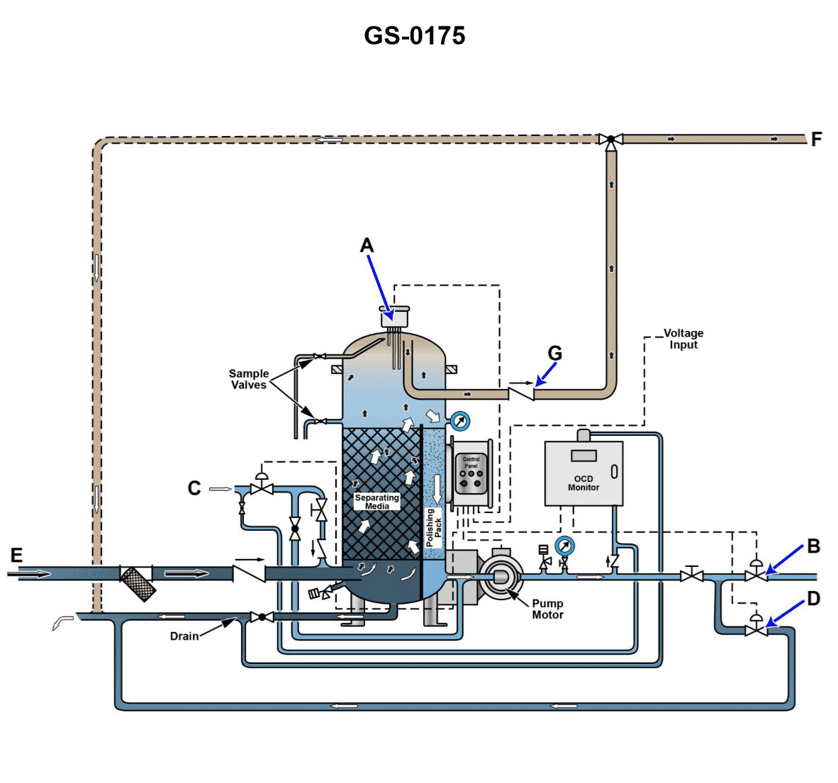
Question: Referring to the illustration, an oil/water separator is in the recirculation mode due to high oil content of the processed water outlet. What action may be required before the unit is capable of discharging overboard once again? Illustration GS-0175
A. Flushing the oil content detector with clean water.
B. Flushing the bilges with an emulsifying agent.
C. Flushing the bilges with a detergent.
D. Cleaning the bilge suction strainer.
The correct answer is A) Flushing the oil content detector with clean water. When an oil/water separator is in recirculation mode due to high oil content in the processed water outlet, it indicates that the oil content detector is not functioning properly. Flushing the oil content detector with clean water can help reset the sensor and restore its proper operation, allowing the separator to discharge the processed water overboard once the oil content is within the regulatory limits. The other options are incorrect because they do not directly address the issue with the oil content detector. Flushing the bilges with an emulsifying agent or detergent (options B and C) may help disperse the oil, but it does not fix the underlying problem with the oil content detector. Cleaning the bilge suction strainer (option D) may improve the overall system performance, but it does not specifically address the oil content detector malfunction.
Question 143
Question: Referring to the illustration, suppose the oily-water separator vessel compound gauge is showing an unusually deep vacuum for operating in the separation processing mode with the separator service pump running. The oil content is 8.3 ppm. What is most likely the cause? Illustration GS-0175
A. The oily-water separator bilge suction strainer is clogged.
B. The oily-water separator vessel relief valve is leaking.
C. The oily-water separator service pump is worn.
D. The bilge water holding tank level is unusually high resulting in a high level alarm.
The correct answer is A) The oily-water separator bilge suction strainer is clogged. The reasoning is that a clogged oily-water separator bilge suction strainer would cause an unusually deep vacuum in the separator vessel, as the pump would have to work harder to pull the water through the restricted strainer. This would result in the observed unusually deep vacuum reading, even with the separator service pump running. The high vacuum indicates a restriction in the system, and a clogged strainer is the most likely cause. The other options are incorrect because a leaking relief valve would not cause a vacuum, a worn pump would likely result in lower vacuum, and a high bilge tank level would not directly impact the vacuum in the separator vessel.
Question 144
Question: Referring to the illustration, suppose after initiating the oil discharge mode, the oily- water separator fails to come out of the oil discharge mode in a timely fashion. Cracking open the upper sampling valve reveals the presence of water exiting under a positive pressure. What is most likely the cause? Illustration GS-0175
A. The oil discharge check valve fails to open, and as a result no oil actually discharges.
B. The upper oil/water interface detection probe fails to end the oil discharge mode.
C. The lower oil/water interface detection probe fails to initiate the oil discharge mode.
D. The clean water supply solenoid fails to open, and as a result provides no discharge pressure.
The correct answer is B) The upper oil/water interface detection probe fails to end the oil discharge mode. This is the correct answer because the key information provided is that the oily-water separator fails to come out of the oil discharge mode in a timely fashion, and there is water exiting under positive pressure from the upper sampling valve. This indicates that the upper oil/water interface detection probe, which is responsible for sensing when the oil layer has been fully discharged and signaling the end of the oil discharge mode, has failed to function properly. The other options are incorrect because they do not address the specific issue of the oily-water separator remaining in the oil discharge mode. For example, option A would result in no oil discharge at all, which is not the case here, and options C and D do not relate to the probe that controls the transition out of the oil discharge mode.
Question 145
Question: Referring to the illustration, suppose while in the oil separation processing mode, the oil content detector display screen shows 17.9 ppm and the oily-water separator is discharging back to the bilge water holding tank for recirculation. What is most likely the cause? Illustration GS-0175
A. The bilge water holding tank contents is excessively contaminated with oil.
B. The oily-water separator bilge suction strainer is excessively clogged.
C. The oily-water separator service pump is excessively worn.
D. The bilge water holding tank level is excessively high resulting in a high level alarm.
The correct answer is A) The bilge water holding tank contents is excessively contaminated with oil. The oil content detector display screen showing 17.9 ppm indicates that the bilge water being discharged from the oily-water separator back to the bilge water holding tank is still excessively contaminated with oil, above the 15 ppm limit. This suggests that the bilge water holding tank contents are excessively contaminated, likely due to continued accumulation of oil in the tank. The other options are less likely causes, as they would not directly result in high oil content in the discharged water.
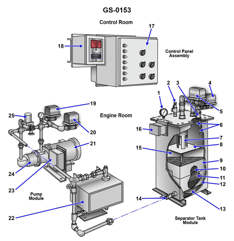
Question 146
Question: If item "1" in the illustrated oily-water separator indicates an abnormally deep vacuum, which of the following conditions is the most probable cause? Illustration GS-0153
A. Coalescer beds are severely fouled.
B. Process water inlet valve, item "5", is open.
C. Suction line inlet strainer is obstructed.
D. No problem exists as a high vacuum should be maintained in the chamber whose vacuum is to be measured.
The correct answer is C) Suction line inlet strainer is obstructed. An abnormally deep vacuum at the oily-water separator's item "1" indicates that the suction line inlet strainer is likely obstructed. This obstruction creates a higher resistance to the flow, resulting in a deeper vacuum at the inlet. The other options are incorrect because: A) Fouled coalescer beds would create back pressure, not a deeper vacuum; B) An open process water inlet valve would not directly affect the vacuum at the inlet; and D) A high vacuum should not be maintained in the chamber whose vacuum is to be measured, as this could indicate an issue with the system.
Question 147
Question: Referring to the illustration, suppose after initiating the oil discharge mode, the oily- water separator fails to come out of the oil discharge mode in a timely fashion. Cracking open the upper sampling valve reveals the presence of oil exiting under positive pressure. What is most likely the cause? Illustration GS-0175
A. The clean water supply solenoid fails to open, and as a result provides no discharge pressure.
B. The oil discharge check valve fails to open, and as a result no oil actually discharges.
C. The lower oil/water interface detection probe fails to initiate the oil discharge mode.
D. The upper oil/water interface detection probe fails to end the oil discharge mode.
The correct answer is B) The oil discharge check valve fails to open, and as a result no oil actually discharges. This is the correct answer because if the oil discharge check valve fails to open, it would prevent the oil from being discharged from the oily-water separator, even though the system is in the oil discharge mode. This would result in the oil backing up and exiting the upper sampling valve under positive pressure, as described in the scenario. The other answer choices are incorrect because: A) the clean water supply solenoid failing to open would not cause the oil to exit under positive pressure; C) the lower oil/water interface detection probe failing would not prevent the oil discharge mode from being initiated; and D) the upper oil/water interface detection probe failing would not cause the oil to continue discharging, but rather would fail to end the oil discharge mode.
Question 148
Question: When the oily-water separator, shown in the illustration, is in operation and processing clear bilge water, what should be the internal water level? Illustration GS-0153
A. The water level should be located in the lower section of the tank as controlled by flow control valve "14".
B. The water level in the tank should be slightly above the upper coalescer bed "9".
C. The water level should be located in the upper section of the tank.
D. No water level is maintained in the tank.
The correct answer is C) The water level should be located in the upper section of the tank. The reasoning is that in a properly functioning oily-water separator, the water level should be maintained in the upper section of the tank. This allows the coalescer bed (item 9) to effectively remove oil and contaminants from the bilge water before it is discharged overboard. Maintaining the water level in the upper section ensures that the oil and contaminants can be effectively separated and contained, rather than being discharged along with the water. The other answer choices are incorrect because: A) The water level should not be in the lower section, as this would bypass the coalescer bed; B) The water level should be above the coalescer bed, not just slightly above it; and D) Some water level must be maintained in the tank for the separator to function properly.
Question 149
Question: The component labeled "A", as shown in the illustration would be identified as the _______________. Illustration GS-0175
A. oil content monitor probe
B. separator vessel pressure relief valve
C. separator vessel vacuum breaker
D. oil/water interface level sensing probe
The correct answer is D) oil/water interface level sensing probe. The oil/water interface level sensing probe is the component labeled "A" in the illustration GS-0175. This probe is responsible for detecting the level of the interface between the oil and water layers within the separator vessel, which is a critical component in oil/water separation systems. The other answer choices are incorrect because they do not accurately describe the function of the component labeled "A" in the illustration. The oil content monitor probe, separator vessel pressure relief valve, and separator vessel vacuum breaker are all different components with distinct purposes within the oil/water separation system.
Question 150
Question: The line labeled "C", as shown in the illustration would be identified as the _______________. Illustration GS-0175
A. oily bilge water inlet line
B. processed water outlet line
C. clean water inlet line
D. waste oil discharge line
The correct answer is C) clean water inlet line. The illustration GS-0175 likely depicts a bilge water management system or similar equipment found on a US Coast Guard certified vessel. The line labeled "C" would be identified as the clean water inlet line, which is used to bring in fresh, clean water into the system, such as for rinsing or flushing purposes. The other answer options are incorrect because: A) the oily bilge water inlet line would be used to bring in contaminated bilge water into the system, B) the processed water outlet line would be used to discharge treated or processed water from the system, and D) the waste oil discharge line would be used to dispose of waste oil separated from the bilge water.
Question 151
Question: The function of item "7" shown in the illustration is to _______________. Illustration GS-0153
A. support the tank access panel
B. allow the oil accumulated to exit the device, while remaining separated from the liquid
C. prevent separated oil from mixing with the incoming bilge water
D. direct the flow of the oily-water mixture against the coalescer bed
The correct answer is C) prevent separated oil from mixing with the incoming bilge water. The function of item "7" in the illustration GS-0153 is to act as a baffle or weir that separates the oil that has been removed from the bilge water, preventing it from being re-mixed with the incoming bilge water. This helps ensure the effectiveness of the oil-water separation device by maintaining the separation of the oil and water phases. The other options are incorrect because: A) the tank access panel is a separate component, B) allowing the oil to exit the device is not the primary function of this specific item, and D) directing the flow against the coalescer bed is the function of a different component in the system.
Question 152
Question: The line labeled "E", as shown in the illustration, would be identified as the _______________. Illustration GS-0175
A. clean water inlet line
B. waste oil outlet line
C. processed water outlet line
D. oily bilge water inlet line
The correct answer is D) oily bilge water inlet line. The illustration GS-0175 is likely depicting the components of a marine oil-water separator or similar pollution control equipment. The line labeled "E" would be identified as the oily bilge water inlet line, as this is the line that carries the oily bilge water from the vessel's bilge into the oil-water separator for processing. The other answer choices are incorrect because they do not accurately describe the function of the line labeled "E" in the context of the illustration. The clean water inlet line, waste oil outlet line, and processed water outlet line would have different designations within the system.
Question 153
Question: What is the normal direction of flow through the device shown in the illustration while operating in the processing mode? Illustration GS-0153
A. The oily-water mixture enters through valve "4" and exits as processed liquid through valve "14".
B. The oily-water mixture enters through valve "5" and exits the separator through valve "14" as processed liquid.
C. The oily-water mixture enters through the pressure control valve "2" and exits with the processed liquid through valve "14".
D. The oily-water mixture enters through valve "14" and exits with the processed liquid through valve "4".
The correct answer is B) The oily-water mixture enters through valve "5" and exits the separator through valve "14" as processed liquid. This is the correct answer because in the normal processing mode, the oily-water mixture enters the separator through the input valve "5" and flows through the separation chamber, where the oil and water are separated. The processed liquid, with the oil removed, then exits the separator through the output valve "14". The other answer choices are incorrect because they do not accurately describe the normal direction of flow through the device while operating in the processing mode. For example, option A incorrectly states that the mixture enters through valve "4", and option C incorrectly states that the mixture enters through the pressure control valve "2".
Question 192
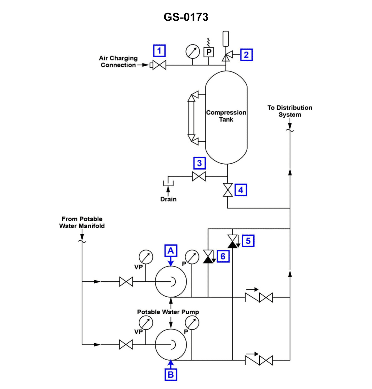
Question: According to the illustration, which of the following conditions would most likely cause Pump "A" to short cycle? Illustration GS-0173
A. The hydro-pneumatic expansion tank is operating with an insufficient air charge.
B. The hydro-pneumatic tank is operating with a low water level.
C. A low water level exists in the potable water storage tank.
D. Pump "A" wearing rings have excessive clearance.
The correct answer is A) The hydro-pneumatic expansion tank is operating with an insufficient air charge. The hydro-pneumatic expansion tank is responsible for maintaining consistent water pressure in the system. If the tank's air charge is insufficient, it will not be able to properly regulate the pressure, causing the pump to short cycle (turn on and off rapidly) in an attempt to maintain the desired pressure. The other options are incorrect because: B) A low water level in the hydro-pneumatic tank would not cause short cycling, it would simply result in the pump running continuously. C) A low water level in the potable water storage tank would not directly affect the pump's operation. D) Excessive wear on the pump's wearing rings would cause a decrease in pump performance, but would not lead to short cycling.
Question 200
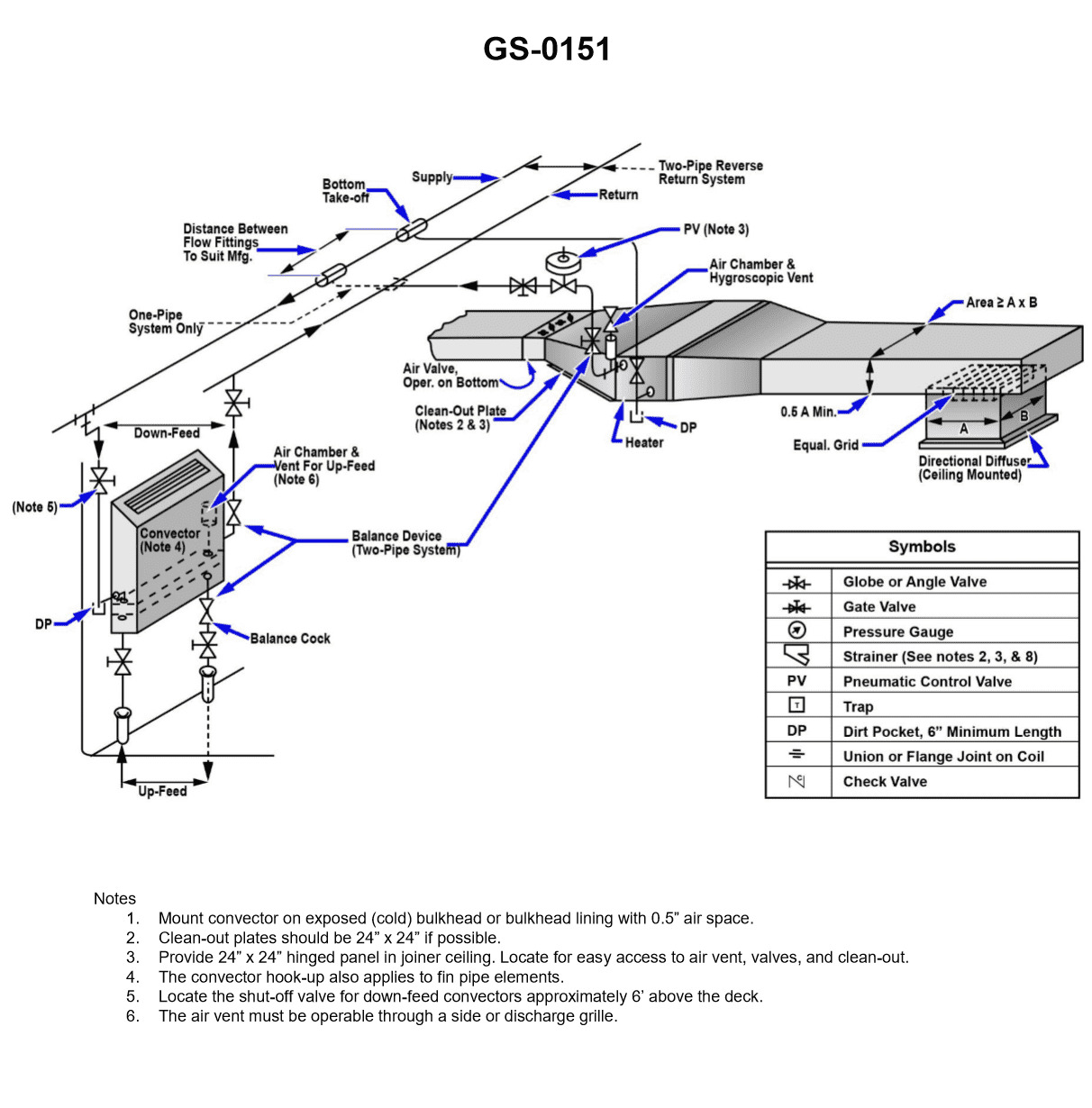
Question: Expansion tanks when used in a ship's low temperature hot water heating system may be of the open or closed type. Referring to the illustrated central-station hookup for a hot water heating system drawing, what would be the normal temperature range of the water? Illustration GS-0151
A. 180oF to 200oF
B. 220oF to 240oF
C. 260oF to 280oF
D. 320oF to 360oF
The correct answer is A) 180°F to 200°F. In a low temperature hot water heating system, the normal temperature range of the water is typically between 180°F and 200°F. This is because low temperature hot water heating systems are designed to operate at relatively lower temperatures compared to high temperature systems, which may reach up to 320°F to 360°F (option D). The other options, B) 220°F to 240°F and C) 260°F to 280°F, are higher temperature ranges that are more characteristic of high temperature hot water heating systems, which are not the focus of the question.
Question 244
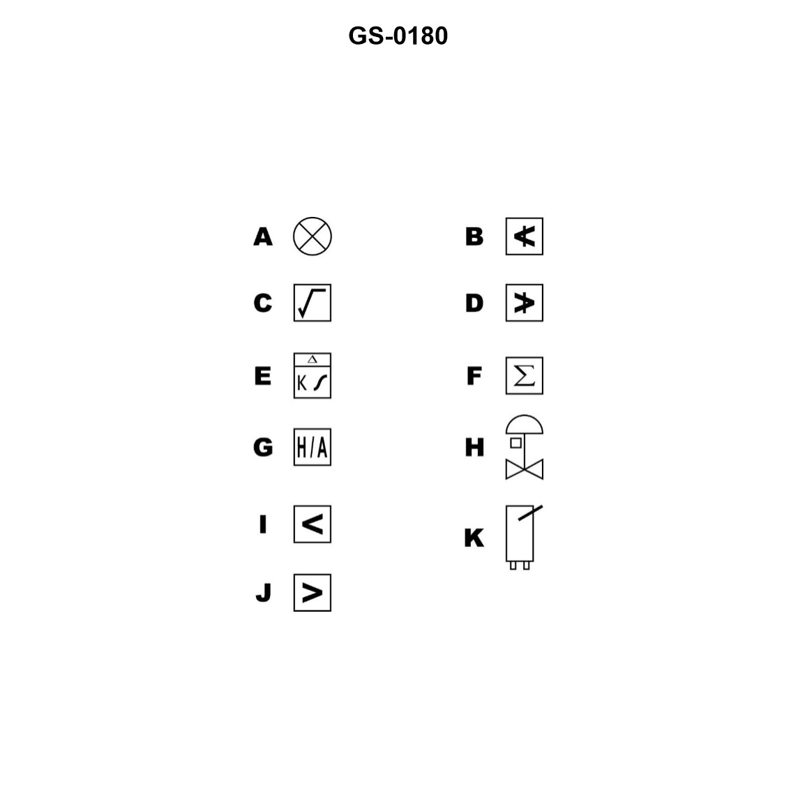
Question: Control system diagrams use standard symbols to describe the component function required for the system to achieve its intended control functions. Standard symbols are used to allow engineers to describe the logic and component functions. Define the function of symbol "I" as shown in the illustration. See Illustration GS-0180
A. High Select Signal Processor.
B. Integral Processor.
C. Low Select Signal Processor.
D. Difference Signal Processor.
The correct answer is C) Low Select Signal Processor. The symbol "I" in control system diagrams represents a low select signal processor, which is a component that selects the lowest signal from multiple inputs. This allows the control system to prioritize the lowest value, which can be important for safety or other critical functions. The other options are incorrect because: A) High Select Signal Processor would select the highest signal, not the lowest; B) Integral Processor refers to a different component that performs integration calculations; and D) Difference Signal Processor would output the difference between two signals, not select the lowest.