Pass Your Coast Guard Licensing Exams!
Study offline, track your progress, and simulate real exams with the Coast Guard Exams app
Motor Plants - Assistant
187 images
Question 10
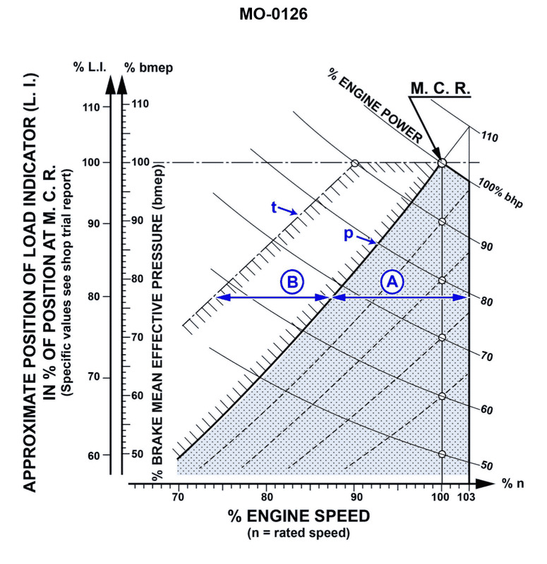
Question: Line "P" in the illustration is the_______________. Illustration MO-0126
A. line of maximum horsepower
B. propeller curve
C. line of maximum efficiency
D. exponential line
The correct answer is B) propeller curve. The propeller curve, also known as the propeller characteristic curve, is a graphical representation of the relationship between the thrust and speed of a marine propeller. This curve shows the performance of the propeller and is an essential tool for understanding the propulsion system of a vessel. The propeller curve is typically labeled as "Line P" in marine engineering illustrations, such as the one referenced (MO-0126). The other options are incorrect because they do not accurately describe the purpose or meaning of Line P in the illustration. Line "A" would represent the line of maximum horsepower, Line "C" would represent the line of maximum efficiency, and Line "D" would represent an exponential line, which is not the typical representation of a propeller curve.
Question 11
Question: Which of the following conditions will cause the engine to operate in area "A" of the diagram shown in the illustration? Illustration MO-0126
A. Fouled hull
B. Damaged propeller blades
C. Inclement weather
D. Excessive propeller cavitation
The correct answer is D) Excessive propeller cavitation. Excessive propeller cavitation can cause the engine to operate in area "A" of the diagram, which is the "Overload" zone. Cavitation occurs when the pressure around the propeller blades drops below the vapor pressure of the water, causing the formation of vapor bubbles. This reduces the propeller's efficiency and can lead to an overload condition for the engine. The other options are incorrect because they would not directly lead to the engine operating in the overload zone. A fouled hull or damaged propeller blades would reduce engine efficiency, but not necessarily cause an overload. Inclement weather could indirectly affect engine performance, but would not directly lead to the overload condition described in the question.
Question 12
Question: The diagram shown in the illustration may be used to determine the proper operation of the engine. Which of the following statements represents an accurate interpretation of the diagram? Illustration MO-0126
A. The engine may be operated in any area of the diagram provided steps are taken to reposition the load indicator.
B. Operation within area "B" is permitted for extended time periods provided no changes are made to the air intake system.
C. Ideally the engine should be operated in area "A"; however, it is permissible to intermittently operate the engine in area "B".
D. Assuming the load indicator reads 90% and the engine speed is at 80% the engine can be operated until maintenance requirements become apparent.
The correct answer is C) Ideally the engine should be operated in area "A"; however, it is permissible to intermittently operate the engine in area "B". This is the correct answer because the diagram likely represents the safe operating range for the engine, where area "A" is the ideal operating zone, and area "B" is a permissible but less desirable zone for intermittent operation. Operating the engine within area "A" ensures the engine runs at optimal efficiency and avoids potential damage. While area "B" may be used, it should be done only briefly, as prolonged operation in that zone could lead to maintenance issues. The other options are incorrect because A) allows operation in any area without proper load management, B) permits extended operation in the less ideal area "B", and D) assumes a specific engine condition without considering the overall operating range.
Question 13
Question: Which of the following conditions would NOT be considered a valid reason for the diesel engine to operate in the area indicated by letter "B" shown in the illustration? Illustration MO-0126
A. Operating the vessel in shallow water
B. Operating with a fouled or damaged propeller
C. Operating the vessel against high winds and current
D. Operating with minimal hull drag and under light draft
The correct answer is D) Operating with minimal hull drag and under light draft. This is correct because operating the diesel engine in the area indicated by letter "B" is typically done to increase engine efficiency and power output in situations where the vessel is operating under high loads, such as against strong winds and currents (option C) or with a fouled or damaged propeller (option B). Operating with minimal hull drag and under light draft (option D) would not be a valid reason for the diesel engine to operate in this less efficient mode, as the engine would not need the additional power output in this scenario. The other options, A) Operating the vessel in shallow water and C) Operating against high winds and current, would be valid reasons for the diesel engine to operate in the less efficient mode indicated by letter "B" in the illustration.
Question 14
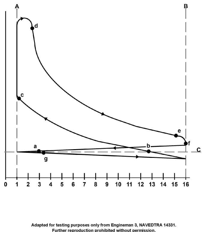
Question: In the pressure-volume diagram shown in the illustration, fuel injection occurs at point_______________. Illustration MO-0035
A. e
B. f
C. c
D. d
The correct answer is C) c. The pressure-volume diagram shown in the illustration MO-0035 represents the operation of a diesel engine. In a diesel engine, fuel injection occurs at the point of maximum compression, which corresponds to point c in the diagram. This is where the piston reaches top dead center and the air inside the cylinder is at its highest pressure and temperature, allowing for efficient combustion of the injected fuel. The other answer choices are incorrect because they do not represent the point of fuel injection in a diesel engine pressure-volume diagram. Option A (e) and B (f) occur at different stages of the engine cycle, while option D (d) represents a different event, such as the opening of the exhaust valve.
Question 16
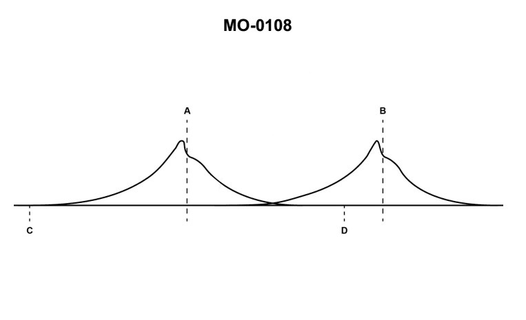
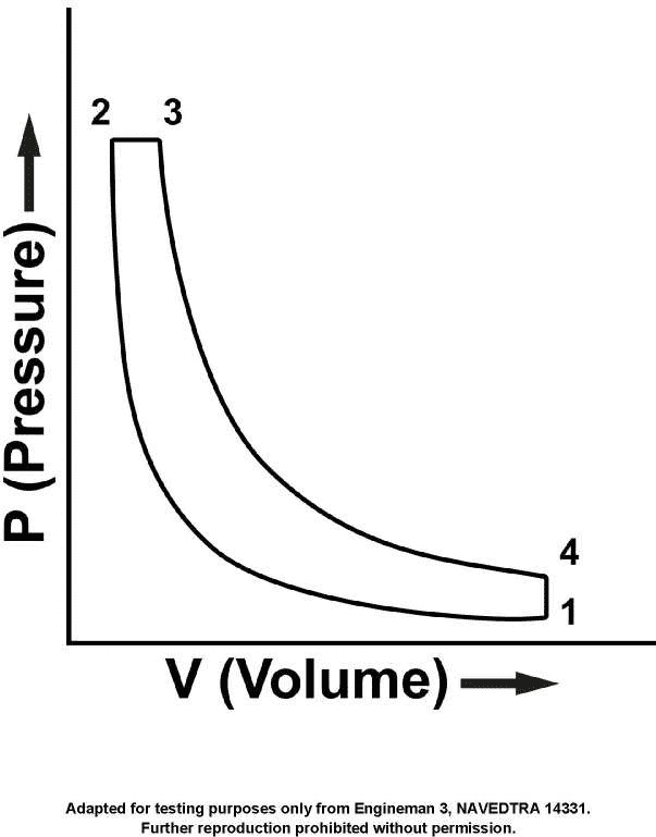
Question: The indicator card shown in the illustration is produced with a/an_______________. MO-0108
A. rotating drum
B. sliding camshaft
C. oscillating drum
D. balanced-diaphragm indicator
The correct answer is A) rotating drum. The indicator card shown in the illustration is produced with a rotating drum. This type of indicator uses a rotating drum to record the pressure-volume diagram of an engine cylinder, which is a key component in evaluating the performance and efficiency of the engine. The rotating drum allows the indicator to capture the changes in pressure and volume over the course of the engine cycle, providing valuable data for the Coast Guard Captain's License Examination. The other options are incorrect because a sliding camshaft, oscillating drum, and balanced-diaphragm indicator are not the mechanisms used to produce the indicator card shown in the illustration.
Question 17
Question: On the indicator card shown in the illustration, lines 'A' and 'B' indicate_______________. Illustration MO-0108
A. the end of ignition
B. bottom dead center
C. the end of injection
D. top dead center
The correct answer is D) top dead center. The indicator card shown in the illustration, MO-0108, depicts the pressure and volume changes inside a diesel engine cylinder over the course of a single engine cycle. The points labeled 'A' and 'B' on the card represent the top dead center (TDC) positions of the piston, where the piston is at its uppermost position in the cylinder. This is the point at which the diesel fuel injection process ends and the power stroke begins. The other answer choices are incorrect because they do not accurately represent the information shown on the indicator card. Line 'A' does not indicate the end of ignition, line 'B' does not indicate bottom dead center, and line 'C' does not indicate the end of injection, as these events are not directly depicted on the illustration provided.
Question 18
Question: In the pressure-volume diagram, shown in the illustration, what occurs between points "e" and "f"? Illustration MO-0035
A. The exhaust valve closes.
B. The intake ports close.
C. Pressure in the cylinder decreases.
D. Volume in the cylinder decreases.
The correct answer is C) Pressure in the cylinder decreases. Between points "e" and "f" on the pressure-volume diagram, the exhaust valve is open and the piston is moving downward, causing the volume in the cylinder to increase. As the volume increases, the pressure in the cylinder decreases, as described by Boyle's law, which states that the pressure and volume of a gas are inversely proportional. The other answer choices are incorrect because: A) The exhaust valve closes after point "f", not between "e" and "f"; B) The intake ports close before point "e"; and D) The volume in the cylinder increases between "e" and "f", not decreases.
Question 19
Question: In the pressure-volume diagram, shown in the illustration, the volume line is divided into 16 units indicating _______________. Illustration MO-0035
A. a cylinder volume of 166 cubic inches
B. compression pressure is 1600 PSI
C. a 16 to 1 compression ratio
D. 16° of crankshaft motion between lines A and B
The correct answer is C) a 16 to 1 compression ratio. The volume line on the pressure-volume diagram is divided into 16 units, which indicates a 16 to 1 compression ratio. This means the volume of the cylinder at the end of the compression stroke is 1/16th of the volume at the beginning of the compression stroke. The compression ratio is a key design parameter for internal combustion engines and is commonly between 8:1 to 16:1 for typical marine applications. The other answer choices are incorrect because they do not correctly interpret the information provided in the pressure-volume diagram. The diagram does not specify the cylinder volume or compression pressure, and the 16 units do not represent crankshaft motion.
Question 20
Question: In the pressure-volume diagram shown in the illustration, curve 'A-d' indicates_______________. Illustration MO-0035
A. combustion at approximately constant pressure
B. opening of exhaust valves
C. fuel injection after dribble
D. start of fuel injection
You are correct, the answer A) combustion at approximately constant pressure is the correct answer. The pressure-volume diagram shown in the illustration indicates the different stages of the diesel engine cycle. Curve 'A-d' represents the combustion process, which occurs at approximately constant pressure. This is a characteristic of the diesel engine cycle, where the fuel is injected and ignited, leading to a steady increase in pressure during the combustion phase. The other answer choices are incorrect because they do not accurately describe the specific section of the pressure-volume diagram labeled 'A-d'. Option B) opening of exhaust valves, C) fuel injection after dribble, and D) start of fuel injection are all different stages of the diesel engine cycle, but they do not correspond to the 'A-d' curve in the illustration.
Question 21
Question: In the pressure-volume diagram, shown in the illustration, what is indicated to have occurred by the line connecting points 'd' and 'e'? Illustration MO-0035
A. The combustion gases have expanded.
B. The crankshaft has rotated 90°.
C. Pressure and volume have increased.
D. The fuel/air charge is compressed.
The correct answer is A) The combustion gases have expanded. The line connecting points 'd' and 'e' on the pressure-volume diagram represents the expansion stroke of the engine cycle. During this stroke, the combustion gases produced from the fuel/air charge ignition expand, pushing the piston down and creating the power to rotate the crankshaft. The other options are incorrect because: B) The crankshaft has rotated 90° is not directly indicated by the line between 'd' and 'e'; C) Pressure and volume have increased is the opposite of what happens during the expansion stroke; and D) The fuel/air charge is compressed occurs earlier in the engine cycle, not during the expansion stroke.
Question 22
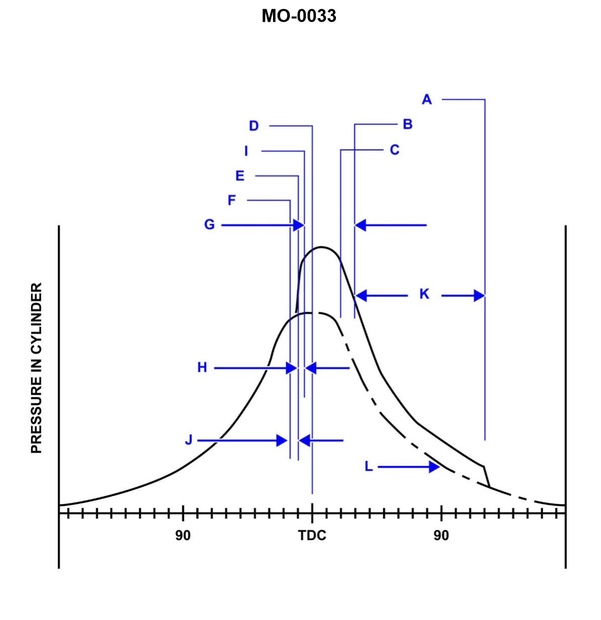
Question: On the cylinder indicator diagram illustrated, the dotted line indicated as 'L' is describing the _______________. Illustration MO-0033
A. cylinder pressure without injection
B. firing pressure at 90 degrees crank angle
C. beginning of compression
D. power expansion curve
The correct answer is A) cylinder pressure without injection. The dotted line labeled 'L' on the cylinder indicator diagram represents the cylinder pressure without injection. This means it shows the pressure in the cylinder due to compression and expansion of the air, without the additional pressure caused by the fuel injection and combustion process. The other answer choices are incorrect because: B) describes the firing pressure at a specific crank angle, C) refers to the start of compression, and D) represents the power expansion curve after combustion, which is a different part of the indicator diagram.
Question 23
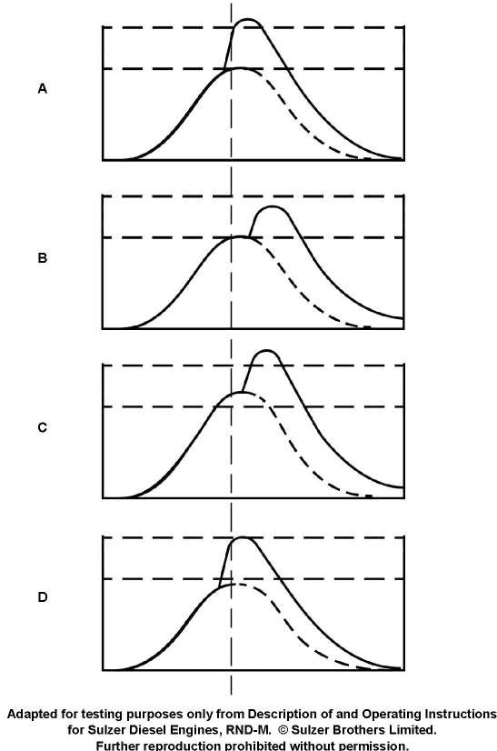
Question: Which of the indicator diagrams illustrated depicts the condition that should be corrected by retarding only the timing? Illustration MO-0029
A. A
B. B
C. C
D. D
The correct answer is A. The indicator diagram that depicts the condition that should be corrected by retarding only the timing is option A. This is because the indicator diagram in option A shows a late closing of the exhaust valve, which can be corrected by retarding the timing of the engine. Retarding the timing will cause the exhaust valve to close later, bringing the indicator diagram closer to the ideal. The other options (B, C, and D) show different engine conditions that would require other adjustments, such as changes to the fuel system or compression, and cannot be corrected by retarding the timing alone.
Question 24
Question: On the indicator card shown in the illustration, lines 'A' and 'B' indicate_______________. Illustration MO-0108
A. top dead center
B. bottom dead center
C. the end of injection
D. the end of ignition
The correct answer is A) top dead center. On the indicator card shown in the illustration MO-0108, lines 'A' and 'B' indicate the position of the piston at top dead center (TDC). This is the point where the piston reaches its highest position in the cylinder, which is a critical reference point for engine timing and performance. The other answer choices are incorrect because they do not accurately describe the information provided in the illustration.
Question 44
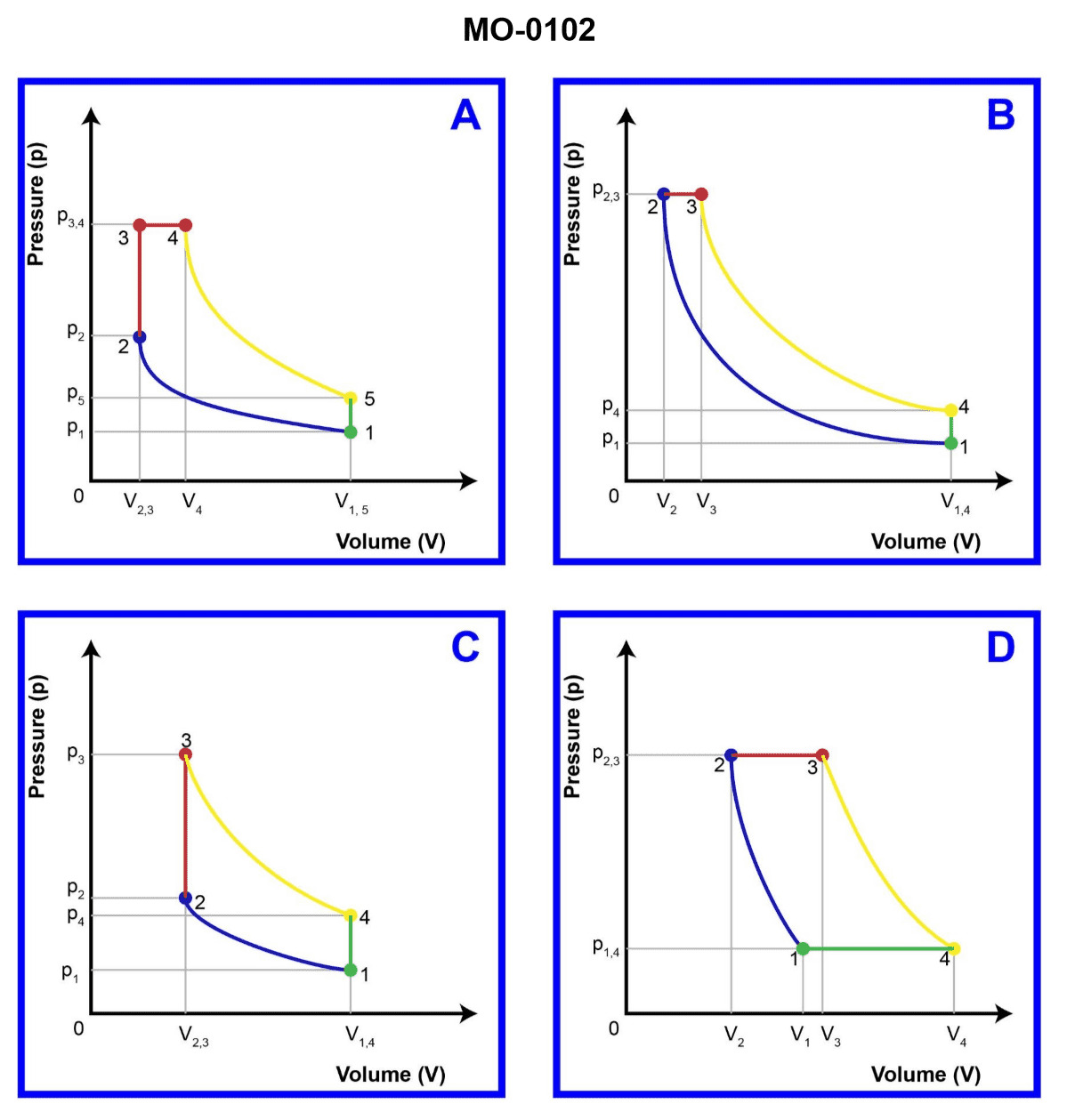
Question: The pressure-volume diagrams illustrated are of four internal combustion engine cycles. Which one represents the theoretical diesel cycle? Illustration MO-0102
A. A
B. B
C. C
D. D
The correct answer is B. The pressure-volume diagram in option B represents the theoretical diesel cycle, which is characterized by constant-pressure combustion. This is in contrast to the constant-volume combustion of the Otto cycle (gasoline engines), which is represented by the diagrams in options A, C, and D. The diesel cycle is the ideal thermodynamic cycle for compression-ignition, internal combustion engines, which is the operating principle of diesel engines. The constant-pressure combustion during the power stroke is a key feature that distinguishes the diesel cycle from other engine cycles.
Question 45
Question: If point #1 in the diagram shown is the beginning of gas compression, which of the cycles listed is being illustrated? Illustration MO-0036
A. Otto
B. Diesel
C. Gas Turbine
D. Rankine
The correct answer is B) Diesel. The diagram MO-0036 illustrates the Diesel cycle, which is characterized by the compression of air and the subsequent injection of fuel at the point of maximum compression. This results in the fuel-air mixture being ignited by the high temperature and pressure of the compressed air, rather than by an external ignition source as in the Otto cycle. The other options are incorrect because the Otto cycle uses an external ignition source, the Gas Turbine cycle uses continuous combustion, and the Rankine cycle is a thermodynamic cycle used in steam power plants, not internal combustion engines.
Question 51
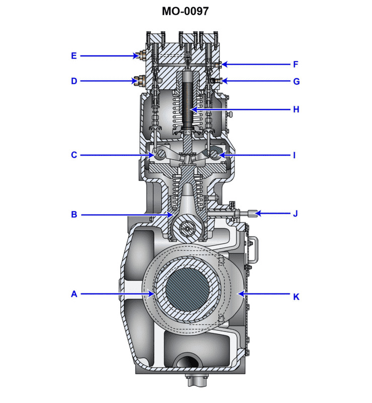
Question: The component shown in the illustration would be identified as a/an_______________. Illustration MO-0097
A. slow-speed engine cylinder liner lubricator
B. slow-speed engine fuel pump
C. centrifugal flyweight governor
D. injector cooling system pump
The correct answer is B) slow-speed engine fuel pump. The fuel pump is a critical component in a slow-speed engine that delivers fuel from the fuel tank to the engine's fuel injection system. It ensures a consistent and reliable supply of fuel to the engine, which is necessary for proper operation. The other answer choices are incorrect because they do not match the function of the component shown in the illustration. A slow-speed engine cylinder liner lubricator, a centrifugal flyweight governor, and an injector cooling system pump serve different purposes in the engine system and are not the component depicted in the illustration.
Question 52
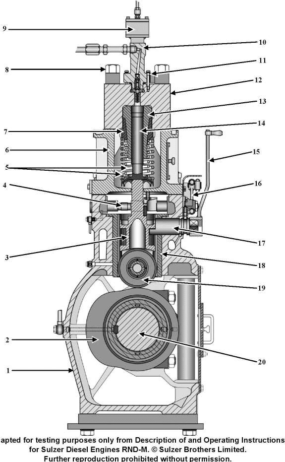
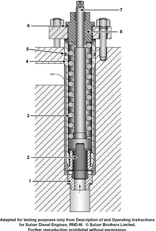
Question: The component identified as item No.15 is used to_______________. Illustration MO-0016
A. test injector popping pressure
B. stop fuel delivery to the injector
C. advance fuel pump timing
D. increase the fuel pump delivery pressure
The correct answer is B) stop fuel delivery to the injector. The component identified as item No. 15 in the illustration MO-0016 is a fuel shutoff valve, which is used to stop the fuel delivery to the injector when the engine is not running or during certain emergency situations. This allows the engine to be shut down quickly and safely. The other answer choices are incorrect because they do not accurately describe the function of the fuel shutoff valve. A) is incorrect as it describes the function of a fuel injector pressure tester, C) is incorrect as it describes the function of a fuel pump timing adjustment, and D) is incorrect as it describes the function of a fuel pump delivery pressure regulator.
Question 53
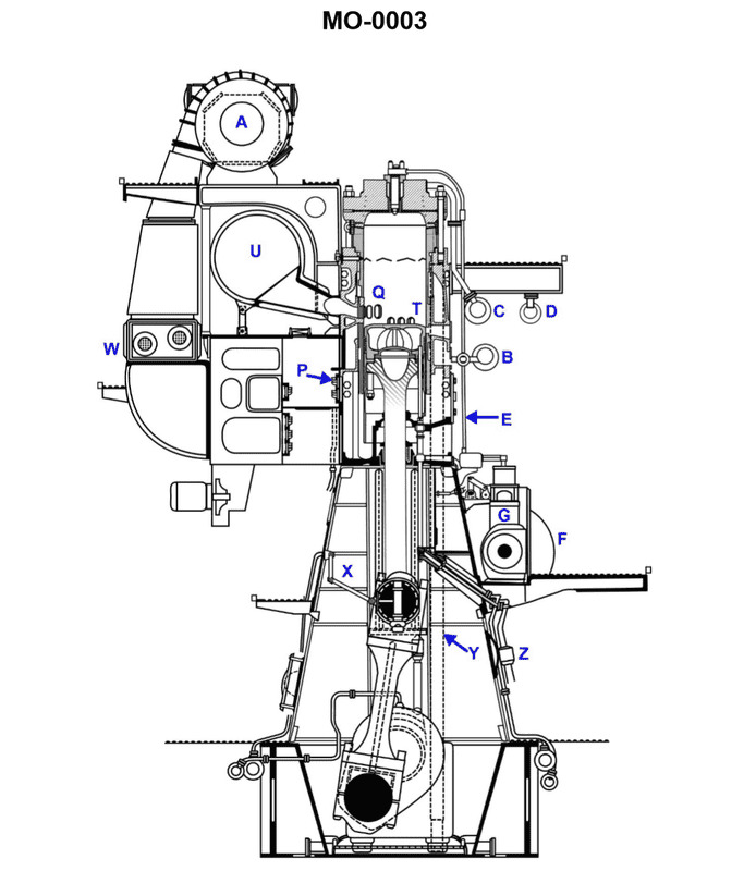
Question: In the large slow-speed main propulsion diesel engine shown in the illustration, the part labeled "G" is the_______________. Illustration MO-0003
A. fuel oil pump
B. jacket water pump
C. crankcase exhaust fan
D. lube oil pump
The correct answer is A) fuel oil pump. The fuel oil pump is responsible for delivering fuel from the fuel tank to the engine's fuel injection system. This is a critical component in a large slow-speed main propulsion diesel engine, as it ensures the proper amount of fuel is supplied to the engine for combustion. The other answer choices are incorrect because: B) the jacket water pump circulates coolant through the engine block, C) the crankcase exhaust fan removes combustion byproducts from the crankcase, and D) the lube oil pump circulates engine lubricating oil, none of which are the specific component labeled "G" in the provided illustration.
Question 54
Question: According to the illustration, initial timing of fuel injection into the cylinder is controlled with the component that is identified as the letter_______________. Illustration MO-0097
A. C
B. H
C. K
D. I
The correct answer is A. The illustration MO-0097 is related to the fuel injection system of a diesel engine. The component identified by the letter "C" controls the initial timing of fuel injection into the cylinder. This component is typically the fuel injection pump or fuel injector, which is responsible for delivering the fuel at the correct timing to the engine cylinder. The other answer choices are incorrect because they do not directly control the initial timing of fuel injection. Option B "H" may be related to the engine governor, option C "K" may be related to the fuel filter, and option D "I" may be related to the fuel line or fuel pump, but none of these components directly control the initial timing of fuel injection into the cylinder.
Question 55
Question: According to the illustration, fuel cutoff timing in the cylinder is controlled with the component that is identified as the letter_______________. Illustration MO-0097
A. C
B. H
C. K
D. I
The correct answer is D. The fuel cutoff timing in the cylinder is controlled by the component identified as the letter I, which is the fuel injection pump. The fuel injection pump is responsible for controlling the timing and delivery of fuel to the engine's cylinders, which directly affects the fuel cutoff timing in the cylinder. The other answer choices (A, B, and C) do not control the fuel cutoff timing in the cylinder. They represent different components of the engine system, such as the cylinder head (C), the camshaft (H), and the crankshaft (K), which do not directly control the fuel cutoff timing.
Question 56
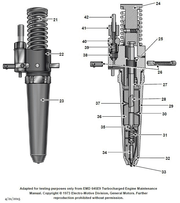
Question: Regarding the fuel injector shown in the illustration, the purpose of piece #38 is to_______________. Illustration MO-0059
A. adjust the fuel rack spring tension
B. filter the fuel
C. maintain fuel pressure at a preset level
D. relieve excess fuel pressure to the suction side of the pump
The correct answer is B) filter the fuel. The purpose of piece #38 in the fuel injector illustration MO-0059 is to filter the fuel. Fuel filters are a critical component in fuel injection systems, as they remove contaminants and impurities from the fuel before it reaches the injectors. This helps prevent damage to the sensitive fuel system components and ensures efficient and reliable engine operation. The other options are incorrect because they do not accurately describe the function of piece #38. Adjusting the fuel rack spring tension, maintaining fuel pressure, and relieving excess fuel pressure are different functions typically performed by other components in the fuel injection system.
Question 60
Question: Which type of diesel engine fuel nozzle is shown in the illustration? Illustration MO-0059
A. Multi-hole
B. Open
C. Self-cleaning
D. Pintle
The correct answer is A) Multi-hole. The multi-hole diesel engine fuel nozzle is the correct type shown in the illustration MO-0059. This type of nozzle is commonly used in diesel engines as it provides a finely atomized fuel spray pattern, which helps with efficient combustion and reduced emissions. The multiple small holes in the nozzle tip facilitate this atomization process. The other options are incorrect because: B) Open nozzles are not commonly used in modern diesel engines, C) Self-cleaning nozzles have additional features to prevent clogging, and D) Pintle nozzles have a central pin that controls the fuel spray pattern, which is different from the multi-hole design.
Question 66
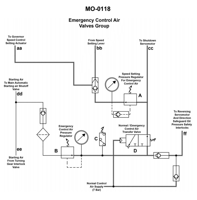
Question: The pneumatic circuit shown in the illustration is part of a control system used with large low-speed diesel engines. The arrangement may be used to control_______________. Illustration MO-0118
A. bridge tachometer variations
B. the proportional offset of the throttle signal
C. main engine speed
D. emergency clutching operations
The correct answer is C) main engine speed. The pneumatic circuit shown in the illustration is part of a control system used with large low-speed diesel engines, which are commonly used as the main propulsion engines for large ships. The purpose of this pneumatic circuit is to control the main engine speed, which is a critical function for regulating the power output and ensuring the engine operates within its designed parameters. The other answer choices are incorrect because they do not accurately reflect the primary purpose of this pneumatic control system. Specifically, it is not used to control bridge tachometer variations (A), the proportional offset of the throttle signal (B), or emergency clutching operations (D). The main function of this system is to govern the speed of the main propulsion engine.
Question 67
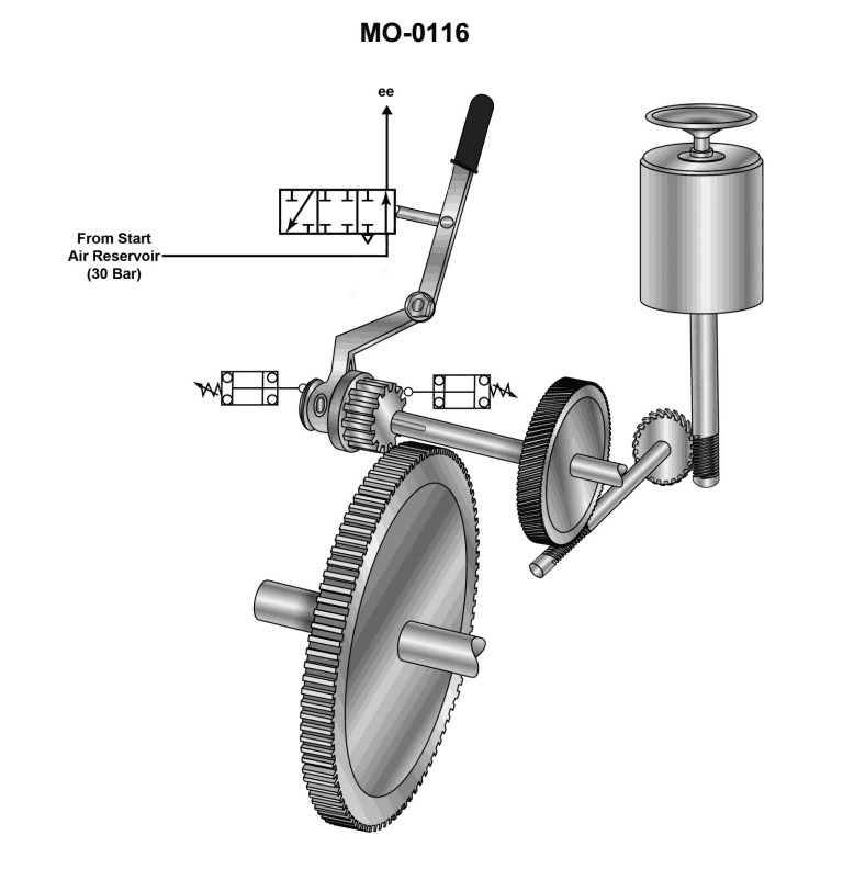
Question: The 3-position, 4-way directional control valve with a 30 bar output at "ee" as shown in the illustration (MO-0116) is a blocking valve associated with the engine turning gear. Which of the following statements describes its function when incorporated into a slow-speed diesel engine starting control air distributor as shown in the illustration (MO-0053)? Illustrations MO-0053 and MO-0116
A. The blocking valve is used to interrupt the supply air at port "C" when the turning gear is engaged
B. The blocking valve is used to interrupt the control air at port "A" when the turning gear is disengaged.
C. The blocking valve is used to interrupt the control air at port "A" when the turning gear is engaged
D. The blocking valve is used to interrupt the supply air at port "C" when the turning gear is disengaged.
The correct answer is C) The blocking valve is used to interrupt the control air at port "A" when the turning gear is engaged. The blocking valve is a 3-position, 4-way directional control valve that is used to control the flow of air in the slow-speed diesel engine starting control air distributor. When the turning gear is engaged, the blocking valve interrupts the control air at port "A", preventing the engine from being started. This is a safety feature to prevent the engine from being started while the turning gear is engaged, which could cause damage to the engine. The other answer choices are incorrect because they do not accurately describe the function of the blocking valve in this system. Option A is incorrect because the blocking valve interrupts the control air, not the supply air. Option B is incorrect because the blocking valve interrupts the control air when the turning gear is engaged, not disengaged. Option D is incorrect because the blocking valve interrupts the control air, not the supply air.
Question 68
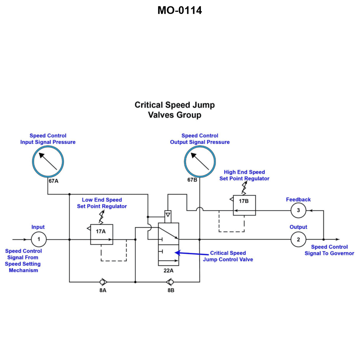
Question: Which of the following statements describes the operation of the circuit shown in the illustration? Illustration MO-0114
A. The output of "2" will always be less than the input at "1" by 0.35 bar
B. B
C. C
D. D
The correct answer is A) The output of "2" will always be less than the input at "1" by 0.35 bar. This is correct because the circuit shown in the illustration depicts a pressure-reducing valve, which is a device used to reduce the pressure of a fluid or gas from a higher inlet pressure to a lower, controlled outlet pressure. The pressure drop across the valve is typically around 0.35 bar, meaning the output pressure at "2" will be approximately 0.35 bar less than the input pressure at "1". The other answer choices are incorrect because they do not accurately describe the operation of a pressure-reducing valve. Choice B, C, and D do not provide the correct relationship between the input and output pressures of the circuit.
Question 69
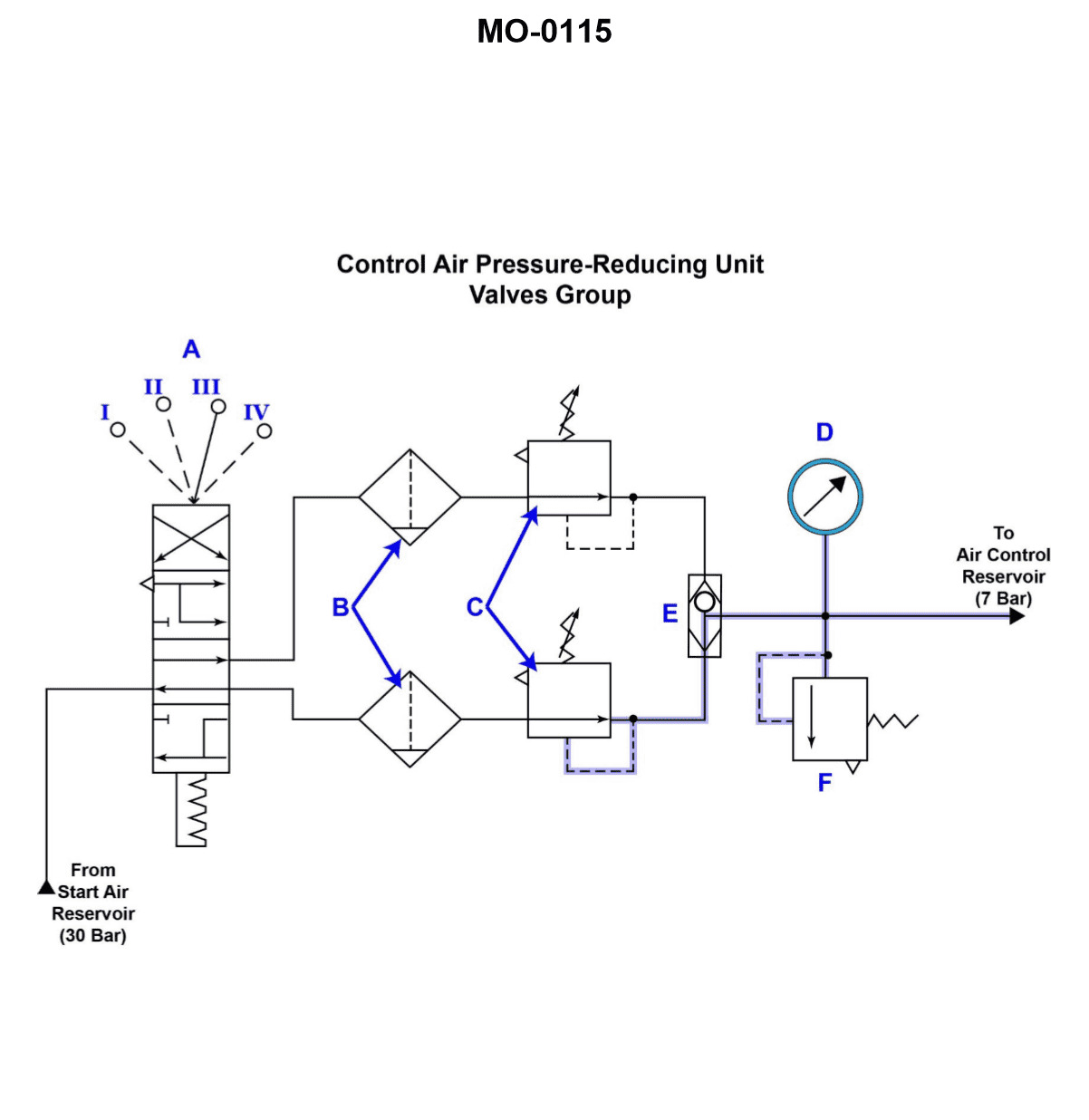
Question: The device represented by the symbol "B" in the illustration is used to_______________. Illustration MO-0115
A. remove all moisture from the system
B. lubricate the air supply
C. reduce the temperature of the air supply as a result of the heat of compression
D. remove most contaminants present in the air supply
The correct answer is D) remove most contaminants present in the air supply. The device represented by the symbol "B" in the illustration MO-0115 is an air filter, which is used to remove most contaminants from the air supply. This is a critical component in compressed air systems, as the air needs to be clean and free of particulates, oil, and other impurities to ensure the proper functioning and safety of the system. The other answer choices are incorrect because: A) does not describe the purpose of the air filter, B) refers to lubricating the air supply, which is not the function of the air filter, and C) refers to reducing the temperature of the air supply, which is also not the purpose of the air filter.
Question 71
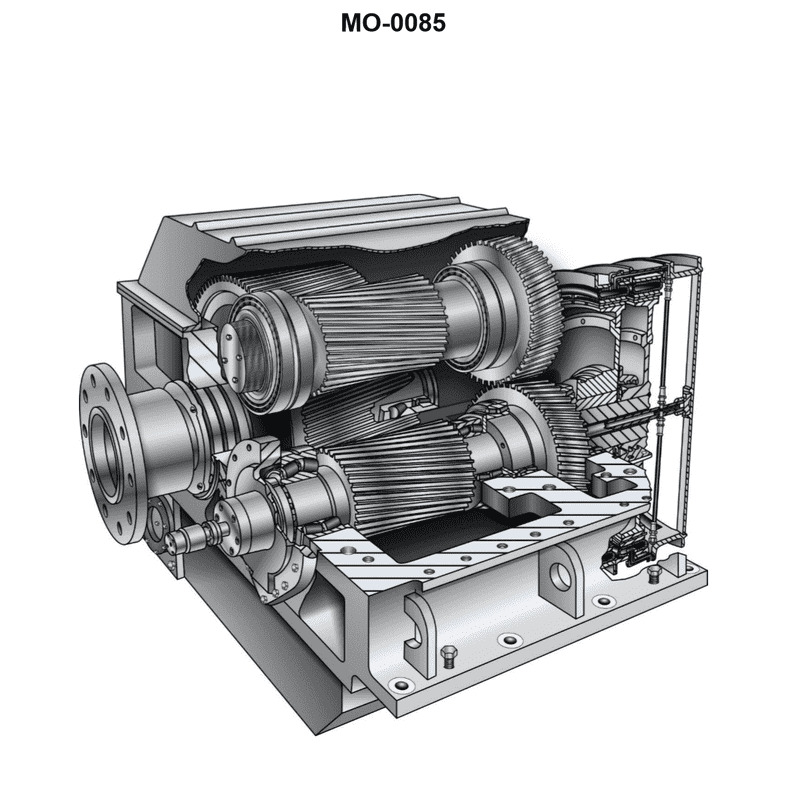
Question: In the reversing reduction gear shown in the illustration, the forward and reverse main pinions are in constant mesh with the main gear. This means the_______________. Illustration MO-0085
A. synchromesh coupling will maintain transition torque control
B. set that is clutched in will rotate as idlers driven from the main gear
C. idling gears rotate in a direction opposite to their rotation when carrying load
D. clutches are engaged by a reduction in control air pressure
The correct answer is C) idling gears rotate in a direction opposite to their rotation when carrying load. In a reversing reduction gear, the forward and reverse main pinions are in constant mesh with the main gear. This means that when the main gear is rotating, the forward and reverse pinions will also be rotating, even if they are not actively driving the system. When the pinions are idling (not clutched in), they will rotate in the opposite direction of their normal rotation when they are actively driving the system. This is a fundamental characteristic of the design of a reversing reduction gear. The other answer choices are incorrect because they do not accurately describe the behavior of the idling gears in a reversing reduction gear system.
Question 74
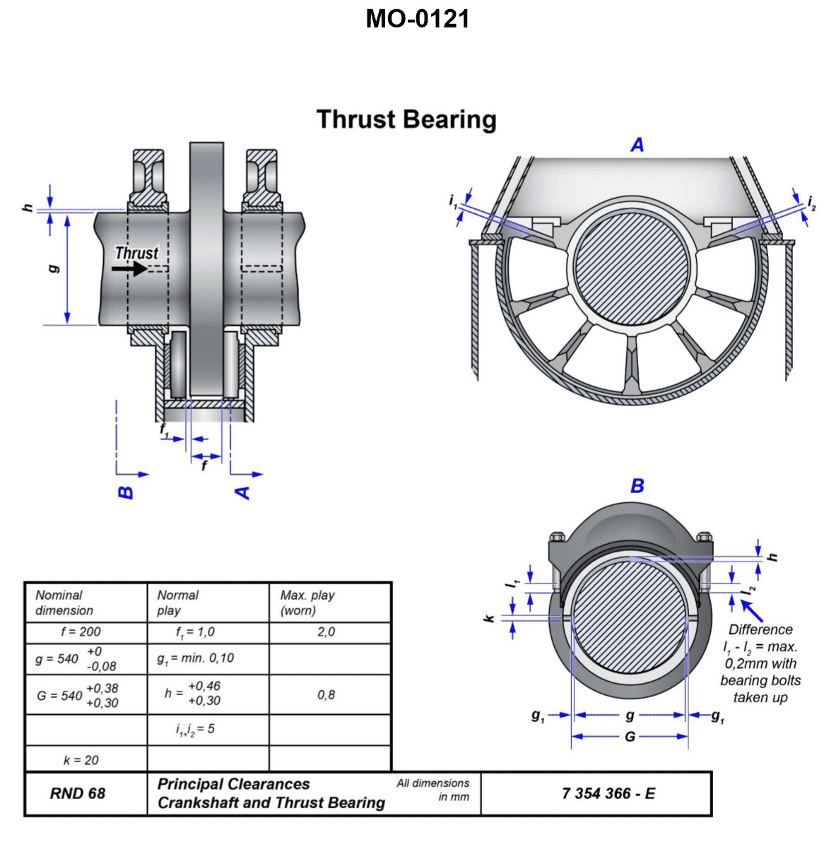
Question: The main engine thrust bearing shown in the illustration contains how many thrust shoes? Illustration MO-0121
A. 6
B. 10
C. 12
D. 20
The correct answer is C) 12 thrust shoes. The main engine thrust bearing typically contains 12 thrust shoes, which are the components responsible for supporting and distributing the thrust load generated by the engine. This configuration is a standard design for marine propulsion systems and is in accordance with the industry standards and practices for engine thrust bearing construction. The other answer choices are incorrect because 6 thrust shoes would be an unusually low number, 10 or 20 thrust shoes would be less common configurations, and 12 thrust shoes is the most prevalent and widely used design for this type of thrust bearing in marine applications.
Question 75
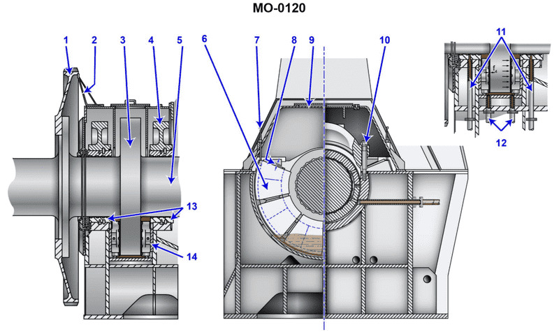
Question: How is lubrication provided to the device shown in the illustration? Illustration MO-0120
A. The lubrication system closely resembles the system used with standard line shaft bearings.
B. A separate system containing oil under extremely high-pressure is used due to its ability to provide a high film strength.
C. Only silicate ester based synthetic oils have the capability and necessary characteristics to be used in this type of application.
D. The lube oil enters through the supply pipes shown as #11 and eventually drains to the main engine sump.
The correct answer is D) The lube oil enters through the supply pipes shown as #11 and eventually drains to the main engine sump. This is the correct answer because the illustration MO-0120 appears to depict a main engine lubrication system, where the lubrication oil is supplied through designated pipes (labeled #11) and then drains back into the main engine sump after performing its lubricating function. This is the standard method of providing lubrication to the main engine components in a marine propulsion system. The other answer choices are incorrect because: A) does not accurately describe the lubrication system shown, B) indicates the use of an excessively high-pressure system which is unlikely for a main engine, and C) specifies the use of a specific lubricant type, which is not the focus of the question.
Question 76
Question: What type of bearing is shown in the illustration? Illustration MO-0120
A. Axial/radial bearing
B. Collar bearing
C. Kingsbury thrust bearing
D. Michell bearing
The correct answer is D) Michell bearing. The Michell bearing, also known as a thrust bearing, is a type of bearing that is designed to support axial loads or thrust loads. This type of bearing is commonly used in applications where there is a need to support heavy loads, such as in marine propulsion systems, which is relevant to the US Coast Guard Captain's License Examinations. The other answer choices are not correct in this context. Axial/radial bearings support both axial and radial loads, collar bearings are used to limit the axial movement of a shaft, and Kingsbury thrust bearings are a specific type of thrust bearing that is not the same as a Michell bearing.
Question 77
Question: What prevents the thrust bearing blocks shown in the illustration from rotating within the housing? Illustration MO-0120
A. The bearing blocks are massive and their weight provides sufficient force to prevent rotation.
B. Found within the thrust bearing cap or cover are extended protrusions to position the thrust shoe segments and maintain minimum clearance.
C. The bearing assembly is specifically designed to allow for rotation, permitting the transmittal of axial forces across a greater surface area and minimizing loading densities.
D. The thrust shoes are dovetailed into the collar.
The correct answer is B) Found within the thrust bearing cap or cover are extended protrusions to position the thrust shoe segments and maintain minimum clearance. The thrust bearing assembly in marine applications is designed to prevent the thrust bearing blocks from rotating within the housing. This is typically achieved through the use of extended protrusions or positioning features within the thrust bearing cap or cover. These protrusions help secure the thrust shoe segments in place and maintain the necessary minimum clearance, preventing the bearing blocks from rotating freely. The other answer choices are incorrect because: A) The weight of the bearing blocks alone is not sufficient to prevent rotation; C) The thrust bearing assembly is designed to transmit axial forces, not allow for rotation; and D) The thrust shoes are not typically dovetailed into the collar in this type of bearing arrangement.
Question 97
Question: Which area of the indicator diagram illustrated, indicates the ignition delay period in a diesel engine cylinder? Illustration MO-0033
A. G
B. H
C. J
D. K
The correct answer is C) J. The ignition delay period in a diesel engine cylinder is represented by the region labeled "J" on the indicator diagram illustrated in MO-0033. This period corresponds to the time between the start of fuel injection and the start of combustion, where the fuel is being injected and mixed with the air in the cylinder before igniting. The other options are incorrect because: A) G represents the compression stroke, B) H represents the expansion or power stroke, and D) K represents the exhaust stroke, none of which directly correspond to the ignition delay period.
Question 100
Question: On the cylinder indicator diagram illustrated, the maximum rise in pressure occurs during the period labeled as_______________. Illustration MO-0033
A. G
B. H
C. J
D. K
The correct answer is B) H. On the cylinder indicator diagram illustrated in MO-0033, the maximum rise in pressure occurs during the period labeled as H, which represents the compression stroke of the engine. During this stroke, the piston moves upward, compressing the air-fuel mixture in the cylinder, leading to a rapid increase in pressure within the cylinder. The other options are incorrect because: A) G represents the exhaust stroke, where the pressure is decreasing as the piston moves downward and the exhaust gases are expelled from the cylinder. C) J represents the power stroke, where the pressure is still high but has already reached its peak during the compression stroke (H). D) K represents the intake stroke, where the pressure is decreasing as the piston moves downward and the air-fuel mixture is drawn into the cylinder.
Question 103
Question: On the cylinder indicator diagram illustrated, the dotted line indicated as 'L' is describing the_______________. Illustration MO-0033
A. power expansion curve
B. beginning of compression
C. cylinder pressure without injection
D. firing pressure at 90 degrees crank angle
The correct answer is C) cylinder pressure without injection. The dotted line labeled 'L' on the cylinder indicator diagram represents the cylinder pressure without injection. This is the pressure curve in the cylinder during the compression and expansion strokes, excluding the effects of fuel injection. The other answer choices are incorrect because: A) The power expansion curve is the solid line on the diagram, not the dotted line labeled 'L'. B) The beginning of compression is not represented by the dotted line 'L'. D) The firing pressure at 90 degrees crank angle is not what the dotted line 'L' represents.
Question 104
Question: Which area of the indicator diagram illustrated, indicates the afterburning period in a diesel engine cylinder? Illustration MO-0033
A. G
B. H
C. J
D. K
The correct answer is D. The afterburning period in a diesel engine cylinder is indicated by the area K on the indicator diagram illustrated in MO-0033. This period represents the continued combustion of the fuel-air mixture after the main injection has ended, resulting in a slow decline in pressure and temperature within the cylinder. The other answer choices are incorrect because: - Areas G, H, and J do not specifically represent the afterburning period on the indicator diagram.
Question 105
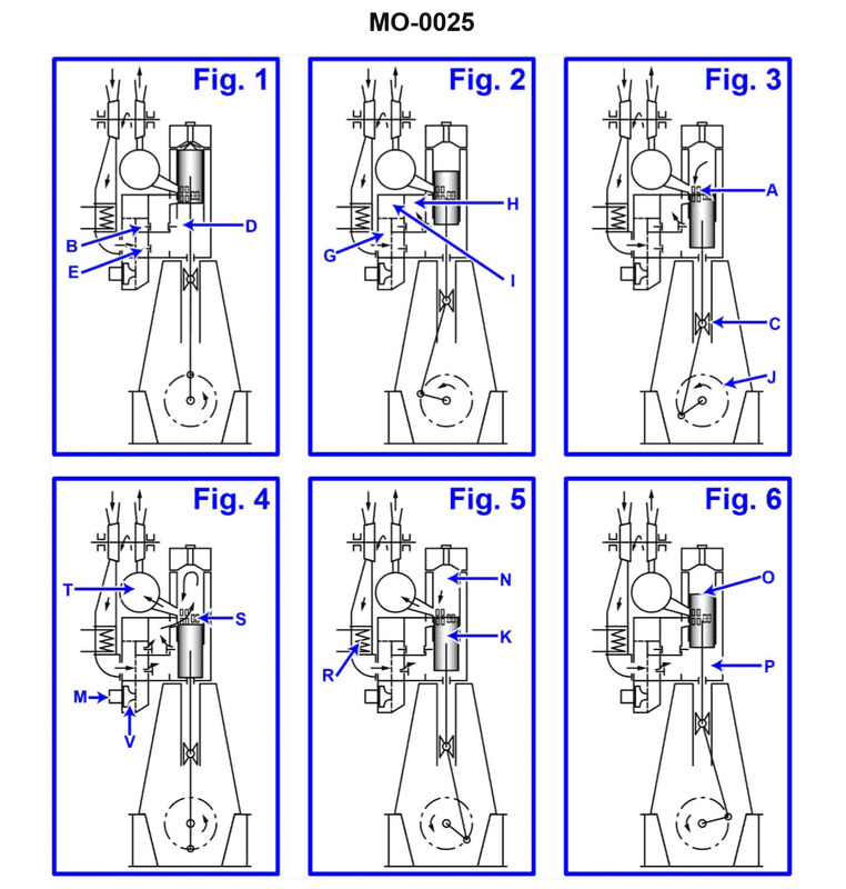
Question: Item labeled 'R' as shown in section 6 of the illustration is identified as the_______________. Illustration MO-0025
A. air filter
B. exhaust manifold
C. non-return scavenge valve
D. aftercooler
The correct answer is D) aftercooler. The item labeled 'R' in the illustration MO-0025 is identified as the aftercooler. The aftercooler is a heat exchanger that cools the compressed air from the turbocharger before it enters the engine's intake manifold. This cooling process increases the density of the air, allowing the engine to produce more power. The other answer choices, such as the air filter, exhaust manifold, and non-return scavenge valve, are not the components labeled 'R' in the given illustration.
Question 106
Question: In the illustrated engine, the fuel camshaft gear drive housing is indicated as letter_______________. Illustration MO-0003
A. B
B. F
C. G
D. Z
The correct answer is B) F. The fuel camshaft gear drive housing is indicated by the letter F in the illustration MO-0003. This can be determined by referencing the key or legend in the illustration, which labels the various components and their corresponding letters. The other answer choices are incorrect because they do not match the labeling provided in the illustration. A) B, C) G, and D) Z do not correspond to the fuel camshaft gear drive housing in this specific diagram.
Question 108
Question: In the diesel engine illustrated, what part is under compression when firing is taking place in a particular cylinder? Illustration MO-0003
A. Tie rod
B. Piston rod nut
C. Lubrication telescopes
D. Piston rod
The correct answer is D) Piston rod. When firing is taking place in a particular cylinder, the piston is under compression. The piston rod, which is connected to the piston, is the part that transmits the force generated by the combustion of the fuel-air mixture to the crankshaft, causing the engine to rotate. The other answer choices, such as the tie rod, piston rod nut, and lubrication telescopes, are not directly involved in the compression and power stroke of the cylinder during the firing process.
Question 109
Question: In the pressure-volume diagram shown in the illustration, the atmospheric pressure line is indicated by line_______________. Illustration MO-0035
A. A
B. B
C. C
D. de
The correct answer is C. The atmospheric pressure line is indicated by line C in the pressure-volume diagram shown in the illustration MO-0035. This is because the atmospheric pressure, which is the pressure exerted by the weight of the Earth's atmosphere, is a constant reference point on the diagram, and is typically represented by a horizontal line. The other answer choices are incorrect because: A) Line A does not represent the atmospheric pressure line. B) Line B does not represent the atmospheric pressure line. D) Line de does not represent the atmospheric pressure line.
Question 110
Question: Which of the indicator diagrams illustrated depicts the condition that should be corrected by retarding only the timing? Illustration MO-0029
A. A
B. B
C. C
D. D
The correct answer is A. The indicator diagram labeled A depicts a condition that should be corrected by retarding the engine timing. This is because the diagram shows a late-closing exhaust valve, which can be addressed by retarding the engine timing to allow the exhaust valve to close earlier in the cycle. The other options, B, C, and D, depict different conditions that would require different corrective actions, such as adjusting the valve clearances or checking for mechanical issues. Retarding the timing would not be the appropriate solution for those scenarios.
Question 112
Question: Which of the indicator diagrams illustrated indicates the condition that should be corrected by retarding the timing, and the fitting of thicker shims to the connecting rod? Illustration MO-0029
A. A
B. B
C. C
D. D
The correct answer is D. The indicator diagram shown in illustration MO-0029, option D, indicates the condition that should be corrected by retarding the timing and the fitting of thicker shims to the connecting rod. This is because the diagram shows a late closing of the exhaust valve, which can cause increased compression pressure and temperature, leading to reduced engine efficiency and potential engine damage. Retarding the timing and increasing the shim thickness can help correct this issue by adjusting the valve timing and reducing the compression ratio. The other options, A, B, and C, do not represent the specific condition that requires the corrective actions mentioned in the question.
Question 118
Question: In the slow-speed diesel engine shown in the illustration, the part labeled "E" is the_______________. Illustration MO-0003
A. high-pressure lube oil line
B. low-pressure lube oil line
C. high-pressure fuel line
D. low-pressure fuel line
The correct answer is C) high-pressure fuel line. In a slow-speed diesel engine, the part labeled "E" in the illustration MO-0003 represents the high-pressure fuel line. This line carries the high-pressure fuel from the fuel injection pump to the fuel injectors, which is a critical component in the diesel engine's fuel delivery system. The other answer choices are incorrect because: A) The high-pressure lube oil line is typically labeled with a different letter. B) The low-pressure lube oil line is a separate component from the high-pressure fuel line. D) The low-pressure fuel line is a different part of the fuel system and is not the component labeled "E" in the illustration.
Question 120
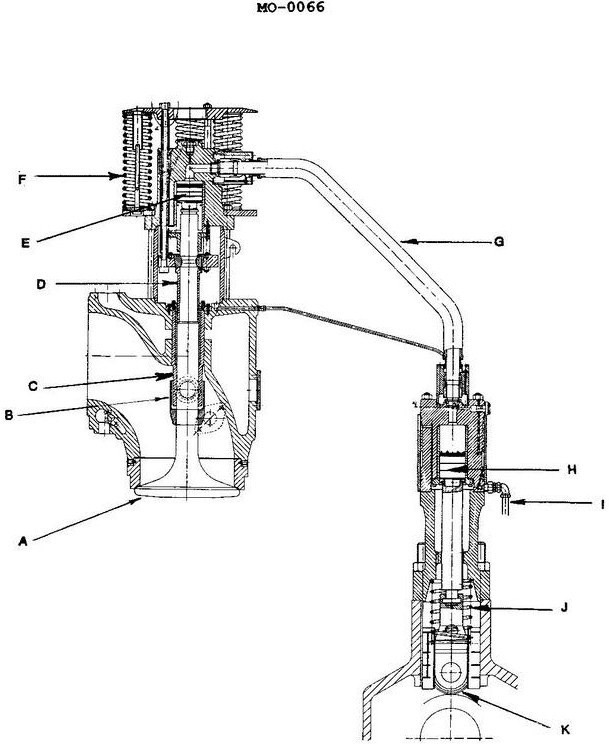
Question: The line identified as "I" in the illustration is used to_______________. Illustration MO-0066
A. deliver fuel oil to the injector
B. supply lubricating oil for actuating the exhaust valve
C. deliver cooling water to the exhaust valve actuating device
D. exhaust gas and vapors from the power cylinder
The correct answer is B) supply lubricating oil for actuating the exhaust valve. The line identified as "I" in the illustration MO-0066 is used to supply lubricating oil to the exhaust valve actuating device. This is necessary to ensure the smooth and efficient operation of the exhaust valve, which is a critical component in the engine's functioning. The other answer choices are incorrect because they do not accurately describe the purpose of the line labeled "I". Option A is incorrect as it refers to fuel oil delivery, which is not the function of this line. Option C is incorrect as it refers to cooling water, which is not the purpose of this particular line. Option D is incorrect as it refers to exhaust gas and vapors, which are not transported through this line.
Question 121
Question: Which letter represents the scavenging air system non-return valve in the illustration? Illustration MO-0003
A. P
B. Q
C. W
D. U
The correct answer is A) P. The scavenging air system non-return valve is represented by the letter P in the illustration MO-0003. This is based on the standard labeling conventions used in marine engineering diagrams, where the non-return valve in the scavenging air system is typically designated with the letter P. The other answer choices are incorrect because Q, W, and U likely represent different components in the overall system, such as valves, connections, or other equipment, but they do not specifically indicate the scavenging air system non-return valve.
Question 123
Question: In the diesel engine shown in the illustration, the purpose of the part labeled "P" is to _______________. Illustration MO-0003
A. boost the scavenge air pressure
B. ensure one way air flow into the air header
C. provide turbulence in the scavenge air
D. cool the scavenge air
The correct answer is B) ensure one way air flow into the air header. The part labeled "P" in the illustration is likely a check valve or non-return valve. The purpose of this valve is to allow air to flow in one direction from the scavenge air system into the air header, but prevent any backflow from the air header into the scavenge air system. This ensures that the scavenge air is directed properly into the engine cylinders. The other answer choices are incorrect because they do not accurately describe the primary function of this valve. Option A refers to boosting the scavenge air pressure, which is a different component's role. Option C describes providing turbulence, which is not the main purpose of this specific part. Option D refers to cooling the scavenge air, which is also not the primary function of this valve.
Question 126
Question: The part labeled "X" shown in the illustration is a_______________. Illustration MO-0003
A. fuel line
B. waterline
C. lube oil line
D. control linkage
The correct answer is C) lube oil line. The illustration MO-0003 is likely showing a diagram of a marine engine or propulsion system. The part labeled "X" is typically a lube oil line, which carries lubricating oil to various components of the engine to reduce friction and wear. The other answer choices are incorrect because: A) A fuel line would not be labeled as "X" in this type of illustration. B) The waterline is not a component of the engine system shown. D) The control linkage is a separate system from the lubrication system.
Question 127
Question: According to the illustration, fuel delivery to the cylinder is terminated and controlled with the component that is identified as the letter_______________. Illustration MO-0097
A. C
B. H
C. K
D. I
The correct answer is D. The component identified as letter "I" in the illustration MO-0097 is responsible for terminating and controlling fuel delivery to the cylinder. This is because "I" represents the fuel injector, which is the component that controls the timing and amount of fuel injected into the cylinder. The fuel injector is the final control point for the fuel supply, and its operation is what determines the fuel delivery to the cylinder. The other answer choices are incorrect because they do not represent the component responsible for controlling fuel delivery. "C" may represent the camshaft, "H" may represent the cylinder head, and "K" may represent the crankshaft, but none of these components directly control the fuel delivery to the cylinder.
Question 128
Question: Which of the following processes is indicated by the flow arrows shown in the illustration? Illustration MO-0026
A. Relief of excessively high-pressure gases from the cylinder.
B. Cooling water bypass flow to the heat sink.
C. Return flow of excess fuel oil from the injector.
D. Return air flow during start-up upon achieving ignition.
The correct answer is A) Relief of excessively high-pressure gases from the cylinder. The flow arrows in the illustration MO-0026 indicate the process of relieving excessively high-pressure gases from the cylinder, which is a safety mechanism required on marine diesel engines to prevent damage or explosion. This process is governed by regulations and best practices for marine engine operation and maintenance. The other options are incorrect because they do not match the process depicted by the flow arrows in the illustration. Option B refers to cooling water flow, option C refers to fuel oil return, and option D refers to air flow during engine start-up, none of which are represented by the flow arrows shown.
Question 130
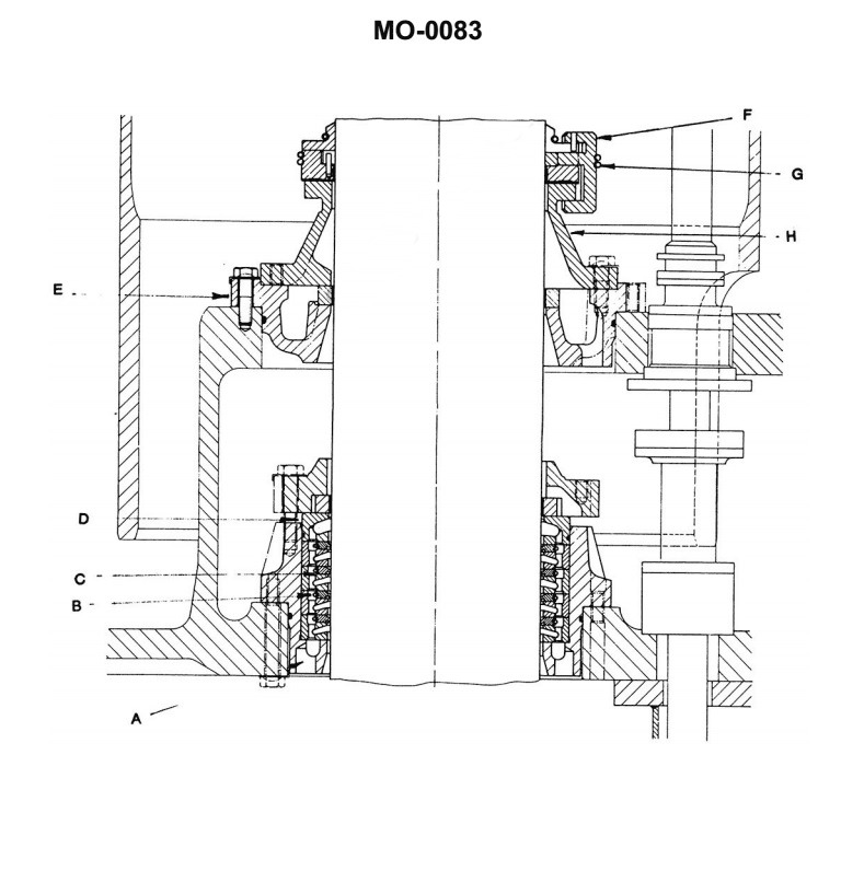
Question: There are two glands provided where the piston rod exits the cylinder shown in the illustration. The purpose of the top gland is to_______________. Illustration MO-0083
A. seal against scavenge air leakage
B. prevent crankcase oil leaking out
C. maintain crankcase vacuum
D. maintain crankcase pressure
The correct answer is A) seal against scavenge air leakage. The top gland where the piston rod exits the cylinder is designed to prevent leakage of the scavenge air from the cylinder. Scavenge air is the air used to purge the cylinder of exhaust gases during the engine's operation. The top gland forms a seal to keep this scavenge air from escaping, which would reduce the engine's efficiency. The other answer choices are incorrect because they do not accurately describe the primary purpose of the top gland. Option B is incorrect as the top gland does not prevent crankcase oil leakage. Option C is incorrect as the top gland does not maintain crankcase vacuum. Option D is incorrect as the top gland does not maintain crankcase pressure.
Question 131
Question: The diesel engine shown in the illustration, the exhaust manifold is indicated by the letter_______________. Illustration MO-0003
A. A
B. B
C. P
D. U
The correct answer is D. The exhaust manifold on the diesel engine shown in the illustration MO-0003 is indicated by the letter U. This is the correct identification based on the labeling provided in the illustration. The other answer choices are incorrect because: A) A does not correspond to the exhaust manifold in the illustration. B) B does not correspond to the exhaust manifold in the illustration. C) P does not correspond to the exhaust manifold in the illustration.
Question 133
Question: The exhaust ports shown in the illustration are identified with the letter '_______________'. Illustration MO-0003
A. B
B. Q
C. T
D. U
The correct answer is B) Q. The illustration MO-0003 shows different parts of a vessel, and the exhaust ports are identified with the letter "Q". This is the correct answer based on the information provided in the illustration. The other answer choices are incorrect because: A) B is not used to identify the exhaust ports in the illustration. C) T is not used to identify the exhaust ports in the illustration. D) U is not used to identify the exhaust ports in the illustration.
Question 136
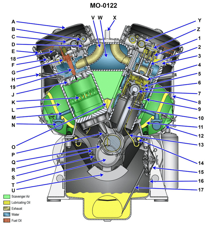
Question: The fuel injector for the diesel engine shown in the illustration, is identified as_______________. Illustration MO-0122
A. "19"
B. "H"
C. "M"
D. "Z"
The correct answer is A) "19". The fuel injector for the diesel engine shown in the illustration is identified as "19" based on the information provided in the image MO-0122. This component labeling convention is commonly used in marine engineering and engine systems to identify specific parts and their locations within the overall engine assembly. The other answer choices (B, C, D) do not correspond to the labeling shown in the provided illustration, and therefore are incorrect.
Question 137
Question: Which letter represents the top deck (valve) cover of the engine shown in the illustration? Illustration MO-0122
A. 'A'
B. 'H'
C. '8'
D. None of the above are correct.
The correct answer is A. The top deck (valve) cover of the engine shown in the illustration MO-0122 is represented by the letter 'A'. This is the correct answer based on the typical engine component labeling conventions used in the illustrations for US Coast Guard Captain's License Examinations. The other answer choices are incorrect because 'H' typically represents the fuel filter, '8' is not a standard label for any engine component, and there is a clearly labeled 'A' component that corresponds to the top deck (valve) cover of the engine in the provided illustration.
Question 138
Question: Device 'E' shown in the illustration is known as the_______________. Illustration MO-0122
A. lube oil manifold
B. extrusion tube assembly
C. overspeed trip shaft
D. fuel manifold
The correct answer is D) fuel manifold. The fuel manifold is a device that distributes fuel to the various components of the engine system. In the illustration MO-0122, Device 'E' is identified as the fuel manifold, which is responsible for delivering fuel from the fuel supply to the engine's fuel injection system or carburetor. The other answer choices are incorrect because: A) The lube oil manifold is a separate component that distributes lubricating oil to various engine parts. B) The extrusion tube assembly is not a common engine component. C) The overspeed trip shaft is a mechanism that prevents engine overspeed, not a fuel distribution system.
Question 139
Question: The diesel engine water inlet jumper illustrated is represented by the letter or number_______________. Illustration MO-0122
A. 'W'
B. 'M'
C. 'N'
D. '14'
The correct answer is B) 'M'. The diesel engine water inlet jumper illustrated in the image MO-0122 is represented by the letter 'M'. This is the standard designation used in marine engineering diagrams and schematics to identify the water inlet jumper, which is a component that connects the main cooling water inlet to the engine. The other answer choices are incorrect because 'W' is typically used to denote the water inlet, 'N' is not a common designation in this context, and '14' does not correspond to the specific component being asked about in the question.
Question 140
Question: Component 'U' of the diesel engine shown in the illustration is called the_______________. Illustration MO-0122
A. frequency tuner
B. crankshaft counterweight
C. frame stiffener
D. main bearing support assembly
The correct answer is B) crankshaft counterweight. The crankshaft counterweight is a critical component of a diesel engine that helps to balance the rotational forces and vibrations generated by the engine's crankshaft. It is designed to counteract the imbalance caused by the movement of the crankshaft, pistons, and connecting rods, ensuring smoother engine operation and reduced stress on the engine components. The other options are incorrect because: A) A frequency tuner is not a component of a diesel engine. C) A frame stiffener is a structural component, not a specific engine part. D) The main bearing support assembly is a different component that supports the crankshaft bearings, not the crankshaft counterweight.
Question 141
Question: The diesel engine wrist pin in the illustration is indicated by the component labeled_______________. Illustration MO-0122
A. '7'
B. '17'
C. 'G'
D. 'S'
The correct answer is A) '7'. The wrist pin, also known as the gudgeon pin, is the component that connects the connecting rod to the piston in a diesel engine. In the illustration MO-0122, the wrist pin is clearly labeled with the number '7', confirming that A) '7' is the correct answer. The other answer choices are incorrect because they do not correspond to the component labeled as the wrist pin in the illustration. B) '17' refers to a different engine component, C) 'G' is not a label used in the illustration, and D) 'S' is also not the label for the wrist pin.
Question 142
Question: Item '17' in the illustration is the dipstick. When should the length of the dipstick be changed? Illustration MO-0122
A. If the operating oil level of the engine is consistently below normal, it will be necessary to use a longer dipstick.
B. If sludge buildup on the bottom of the pan becomes excessive, it will become necessary to shorten the dipstick to accommodate for the false oil level reading.
C. When changing the oil in an operating engine, it may become necessary to use a longer stick to obtain the exact location of the oil level at all times.
D. In most situations this would never be done.
The correct answer is D) In most situations this would never be done. The length of the dipstick should not need to be changed. The dipstick is designed to accurately measure the oil level in the engine crankcase. Changing the length of the dipstick would provide inaccurate oil level readings, which could lead to engine damage if the oil level is not properly maintained. The dipstick length is set by the engine manufacturer and should not be altered. The other answer choices describe situations that would not require changing the dipstick length, as the oil level should be addressed through other means, such as adding or changing the oil, rather than modifying the dipstick.
Question 144
Question: The water inlet manifold for the diesel engine shown in the illustration is represented by the letter or number_______________. Illustration MO-0122
A. "M"
B. "N"
C. "W"
D. "13"
The correct answer is B) "N". The water inlet manifold for the diesel engine shown in the illustration MO-0122 is represented by the letter "N". This can be determined by examining the diagram and identifying the component labeled with the letter "N", which corresponds to the water inlet manifold based on the typical configuration of a diesel engine's cooling system. The other options are incorrect because "M" likely represents a different component, "W" is not a common label for the water inlet manifold, and "13" does not correspond to the lettered labeling system used in the illustration.
Question 145
Question: The diesel engine component labeled "3", shown in the illustration is called the_______________. Illustration MO-0122
A. scavenging air space
B. cylinder liner
C. head valve assembly
D. cylinder head
The correct answer is D) cylinder head. The cylinder head is the component labeled "3" in the illustration MO-0122. The cylinder head is the top part of the diesel engine cylinder, which houses the intake and exhaust valves, as well as the fuel injector. It is responsible for controlling the flow of air and fuel into and out of the cylinder during the engine's operating cycle. The other options are incorrect because: A) the scavenging air space is not a component of the engine, but rather the area where the fresh air enters the cylinder; B) the cylinder liner is the inner lining of the cylinder, not the cylinder head; and C) the head valve assembly is a separate component that controls the opening and closing of the intake and exhaust valves, not the entire cylinder head assembly.
Question 146
Question: The diesel engine connecting rods shown in the illustration are distinctively named_______________. Illustration MO-0122
A. fork and blade
B. male and female
C. hook and nail
D. left hand and right hand
The correct answer is A) fork and blade. The connecting rods in a diesel engine are distinctively named "fork and blade" due to their unique shape and design. The fork end of the connecting rod attaches to the crankshaft, while the blade end connects to the piston. This distinctive configuration allows the engine to efficiently transfer the power generated by the combustion process to the crankshaft, enabling the engine to operate. The other answer choices are incorrect because they do not accurately describe the specific naming convention for diesel engine connecting rods, which is the "fork and blade" design.
Question 147
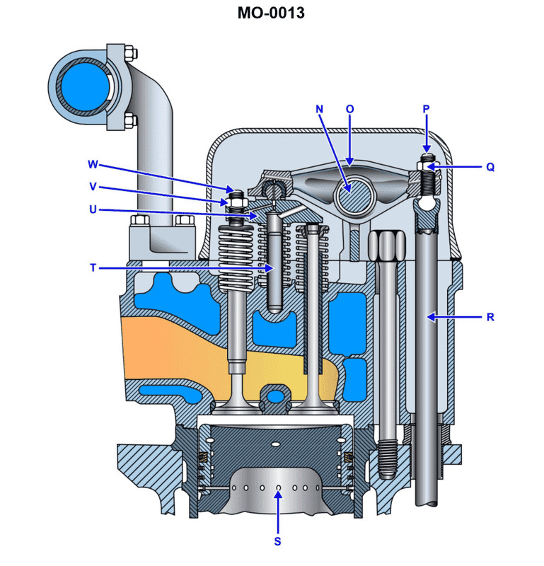
Question: Which of the listed cylinder head design features is shown in the illustration? Illustration MO-0013
A. The valve cages are provided for the exhaust valves.
B. The engine is equipped with a dry liner.
C. A gastight seal is provided by a gasket between the cylinder head and cylinder liner.
D. The engine cylinder head is fitted with replaceable valve seats.
The correct answer is D) The engine cylinder head is fitted with replaceable valve seats. This is the correct answer because the illustration MO-0013 shows a cylinder head design that features replaceable valve seats, which allow the valve seats to be replaced when they become worn or damaged. This design is common in marine engines to facilitate maintenance and extend the engine's lifespan. The other answer choices are incorrect because they do not accurately describe the features shown in the illustration. The valve cages are not provided for the exhaust valves (A), the engine does not have a dry liner (B), and a gastight seal is provided by a gasket between the cylinder head and cylinder block, not the cylinder liner (C).
Question 148
Question: Which of the following represents the diesel engine camshaft shown in the illustration and its relative rotating speed? Illustration MO-0122
A. "B" is the camshaft and it rotates at one-half of the crankshaft speed.
B. "B" is the camshaft and its rpm will match that of the flywheel.
C. "T" is the camshaft and its speed equals crankshaft speed.
D. "Y" is the main camshaft drive and rotates at crankshaft speed.
The correct answer is B) "B" is the camshaft and its rpm will match that of the flywheel. The camshaft in a diesel engine is responsible for opening and closing the engine's valves, and it is typically driven by the crankshaft at a reduced speed. In a four-stroke diesel engine, the camshaft rotates at half the speed of the crankshaft, as it takes two crankshaft revolutions to complete one full cycle of the engine. However, in the illustration provided (MO-0122), the "B" label is indicating the camshaft, and its speed is specified to match that of the flywheel, which is directly connected to the crankshaft. Therefore, the correct answer is that the camshaft labeled "B" rotates at the same speed as the flywheel. The other options are incorrect because they do not accurately describe the relationship between the camshaft and the crankshaft in the given illustration.
Question 149
Question: The diesel engine rocker arms shown in the illustration serve to_______________. Illustration MO-0122
A. convert rotational energy to reciprocating pressures
B. operate the exhaust and starting valves
C. open the exhaust valves and operate the unit injectors
D. open the intake and exhaust valves
The correct answer is C) open the exhaust valves and operate the unit injectors. The rocker arms in a diesel engine serve to convert the rotational motion of the camshaft into the reciprocating motion needed to open and close the engine's intake and exhaust valves. They also actuate the unit injectors, which are responsible for injecting fuel into the engine's cylinders. The other answer choices are incorrect because: A) rocker arms do not directly convert rotational energy to pressure, B) the rocker arms do not operate the starting valves, and D) while the rocker arms do open the intake and exhaust valves, they also have the additional function of operating the unit injectors.
Question 150
Question: The rocker arms of the diesel engine shown in the illustration are indicated by_______________. Illustration MO-0122
A. "C" and "Y"
B. "B"
C. "C"
D. "D"
The correct answer is A) "C" and "Y". The illustration MO-0122 clearly shows the rocker arms of the diesel engine labeled as "C" and "Y". The rocker arms are responsible for transferring the motion from the camshaft to the engine's valves, and they are a critical component in the proper functioning of the diesel engine. The other options are incorrect because: B) "B" does not indicate the rocker arms, C) "C" alone does not encompass all the rocker arms shown in the illustration, and D) "D" refers to a different component of the engine, not the rocker arms.
Question 151
Question: The injector rack of the diesel engine shown in the illustration is indicated by the component labeled_______________. Illustration MO-0122
A. "B"
B. "E"
C. "F"
D. "G"
The correct answer is D. The injector rack of the diesel engine shown in the illustration is indicated by the component labeled "G". The injector rack is a critical component in a diesel engine, as it is responsible for delivering the fuel to the engine's cylinders. The labeling in the provided illustration clearly identifies the injector rack as component "G", which makes this the correct answer. The other answer choices are incorrect because they label different components in the engine, such as the fuel pump ("B"), the engine block ("E"), and the fuel filter ("F"), which are not the injector rack.
Question 152
Question: Which letter represents the exhaust gas exit point for the diesel engine shown in the illustration? Illustration MO-0122
A. "K"
B. "J"
C. "N"
D. "V"
The correct answer is D. The illustration MO-0122 shows the components of a diesel engine, and the letter "V" represents the exhaust gas exit point. This is in accordance with the standard labeling conventions used in marine engineering diagrams, where the exhaust outlet is typically designated by the letter "V". The other answer choices are incorrect because "K" is not used to represent the exhaust gas exit point, "J" is likely used for another component, and "N" is not a standard label for this particular engine system.
Question 153
Question: The main lube oil manifold, for the diesel engine shown in the illustration, is represented by the letter or number_______________. Illustration MO-0122
A. "11"
B. "17"
C. "N"
D. "O"
The correct answer is D. The main lube oil manifold for the diesel engine shown in the illustration MO-0122 is represented by the letter "O". This is based on the standard conventions and labeling used in marine engineering schematics and diagrams, where the letter "O" is commonly used to denote the main lube oil manifold or system. The other answer choices, "11", "17", and "N", do not correspond to the standard labeling conventions for a main lube oil manifold and are therefore incorrect.
Question 155
Question: The diesel engine component labeled "1", shown in the illustration is called a/an_______________. Illustration MO-0122
A. external thread
B. exhaust valve spring
C. inlet valve spring
D. conical speed/surge prevention device
The correct answer is B) exhaust valve spring. The exhaust valve spring is responsible for closing the exhaust valve in a diesel engine, allowing the engine to properly expel the exhaust gases after the combustion cycle. This component is a critical part of the engine's valve train and is labeled as "1" in the provided illustration MO-0122. The other answer choices are incorrect because: A) external thread is not a engine component, C) inlet valve spring controls the intake valve, and D) conical speed/surge prevention device is not a standard diesel engine component.
Question 156
Question: The inlet valves for the diesel engine shown in the illustration are indicated by the letter or number_______________. Illustration MO-0122
A. "2"
B. "19"
C. "H"
D. none of the above are correct
The correct answer is D) none of the above are correct. The illustration MO-0122 is not provided, so without seeing the specific illustration, it is not possible to determine which letter or number corresponds to the inlet valves for the diesel engine. The answer choices given do not provide enough information to definitively identify the correct location on the illustration. Therefore, none of the answer choices can be confirmed as correct based on the information given.
Question 157
Question: The diesel engine component labeled "5", shown in the illustration is known as the_______________. Illustration MO-0122
A. heat sink space
B. piston crown
C. connecting rod end assembly
D. piston thrust washer
The correct answer is D) piston thrust washer. The piston thrust washer is the component labeled "5" in the diesel engine illustration MO-0122. This washer is responsible for guiding the piston as it moves within the cylinder, helping to maintain proper alignment and reduce wear on the piston and cylinder walls. The other answer choices are incorrect because: A) a heat sink space is not a specific engine component, B) the piston crown is the top of the piston, and C) the connecting rod end assembly is a separate component from the piston thrust washer.
Question 158
Question: What is the function of component "13" shown in the illustration? Illustration MO-0122
A. The inlet jumper directs cooling water to the cylinder liner.
B. The device delivers the oil for piston cooling, in addition to liner lubrication.
C. The water pipe is the mechanism in which the 'shaker' method of piston cooling is accomplished.
D. The sample tube monitors the cylinder for evidence of piston blow-by.
The correct answer is B) The device delivers the oil for piston cooling, in addition to liner lubrication. This is the correct answer because the component labeled "13" in the illustration MO-0122 is likely the oil supply pipe or line that provides lubricating and cooling oil to the piston and cylinder liner. Proper piston cooling and lubrication are critical for the safe and efficient operation of marine diesel engines, as required by US Coast Guard regulations. The other answer choices are incorrect because they do not accurately describe the function of the specific component shown in the illustration. Option A refers to cooling water, option C describes a different piston cooling method, and option D is monitoring for piston blow-by, which is a different engine function.
Question 165
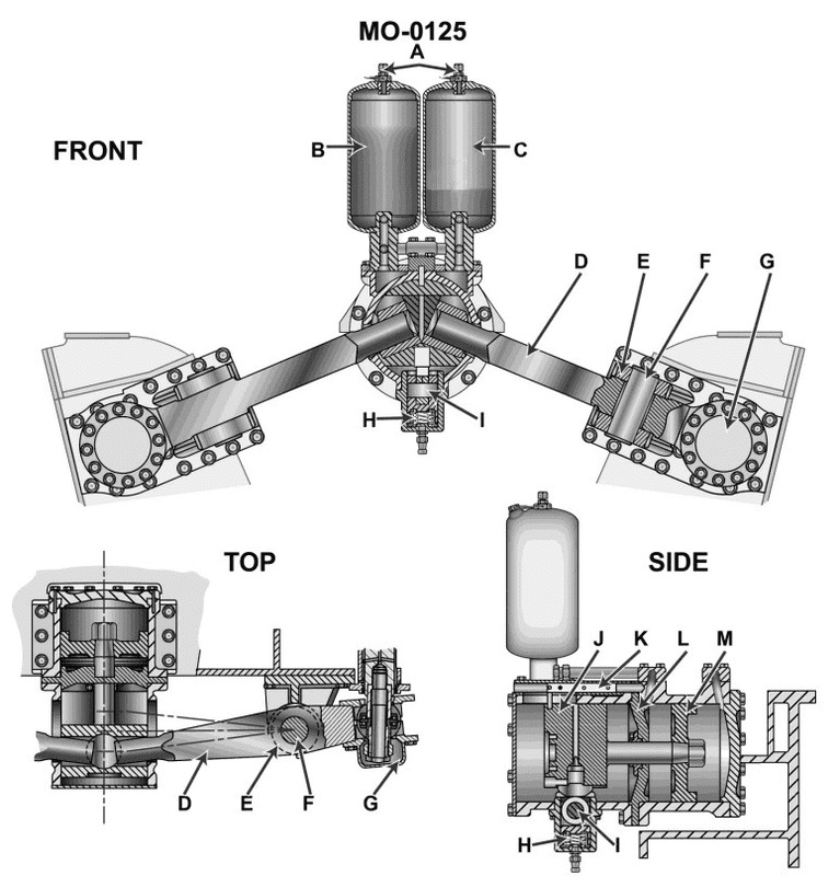
Question: The cylinders labeled "B" and "C" in the illustration are used to_______________. Illustration MO-0125
A. provide oil to lubricate component "F"
B. supply a specific volume of oil to the engine governor
C. provide the required quantity of grease at specified maintenance intervals
D. supply the force required to shift the engine camshafts axially to reverse engine rotation
The correct answer is D) supply the force required to shift the engine camshafts axially to reverse engine rotation. The cylinders labeled "B" and "C" in the illustration are likely part of the engine's reversing mechanism, which allows the engine to be operated in reverse. This mechanism uses hydraulic pressure to shift the camshafts axially, changing the valve timing and engine rotation direction. This is a common feature in marine engines to enable maneuvering and docking operations. The other answer choices are incorrect because they do not accurately describe the function of the "B" and "C" cylinders in the illustration. Providing oil to lubricate component "F", supplying oil to the engine governor, or providing grease at maintenance intervals are not the primary functions of these specific cylinders.
Question 166
Question: The component labeled "A" on the engine reversing device shown in the illustration, performs its function by transmitting_______________. Illustration MO-0125
A. an electric voltage which energizes solenoids to de-clutch the engine
B. a fuel oil pressure signal which reverses the engine governor control cylinder
C. a hydraulic pressure which shifts an alternate set of camshaft followers to ride on the engine camshaft
D. a pneumatic signal which activates a hydraulic control cylinder allowing the camshaft to shift axially
The correct answer is D) a pneumatic signal which activates a hydraulic control cylinder allowing the camshaft to shift axially. The component labeled "A" on the engine reversing device is responsible for transmitting a pneumatic signal that activates a hydraulic control cylinder. This allows the camshaft to shift axially, which in turn reverses the direction of the engine. The pneumatic signal is used to control the hydraulic system, rather than using an electric voltage, fuel oil pressure, or direct mechanical shifting of the camshaft followers. The other answer choices are incorrect because they do not accurately describe the function of the "A" component. Option A involves an electric voltage, option B involves a fuel oil pressure signal, and option C involves a direct hydraulic pressure shifting the camshaft followers, rather than the pneumatic-hydraulic system described in the correct answer.
Question 180
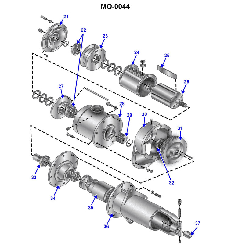
Question: The illustration is of a/an_______________. Illustration MO-0044
A. air driven starter motor assembly
B. power take-off driven, vane type, air compressor
C. air driven DC generator
D. battery powered, electric motor driven vane type, hydraulic pump
The correct answer is A) air driven starter motor assembly. This is the correct answer because the illustration, labeled MO-0044, depicts an air-driven starter motor assembly, which is a common component in marine propulsion systems. Air-driven starter motors are used to crank and start diesel engines, providing the initial rotation to get the engine running. The other answer choices, while describing other types of air-powered or hydraulic components, do not accurately match the specific illustration provided. The key distinguishing feature here is that the illustration depicts a starter motor assembly, which is responsible for initiating engine start-up, rather than a compressor, generator, or hydraulic pump.
Question 182
Question: During the starting of a diesel engine, compression gases are prevented from backing into the air starting system, shown in the illustration, by the_______________. Illustration MO-0046
A. cylinder air starting check valves
B. individual distribution valves
C. high-pressure in the starting air manifold
D. air starting control valve
The correct answer is A) cylinder air starting check valves. During the starting of a diesel engine, the cylinder air starting check valves prevent compression gases from backing into the air starting system. These check valves are one-way valves that allow air to flow from the air starting system into the engine cylinders, but not in the reverse direction. This prevents the high-pressure compression gases in the cylinders from being forced back into the air starting system, which could potentially damage the components in the air starting system. The other answer choices are incorrect because: B) individual distribution valves are not responsible for preventing backflow, C) the high pressure in the starting air manifold alone does not prevent backflow, and D) the air starting control valve controls the starting air supply but does not directly prevent backflow.
Question 183
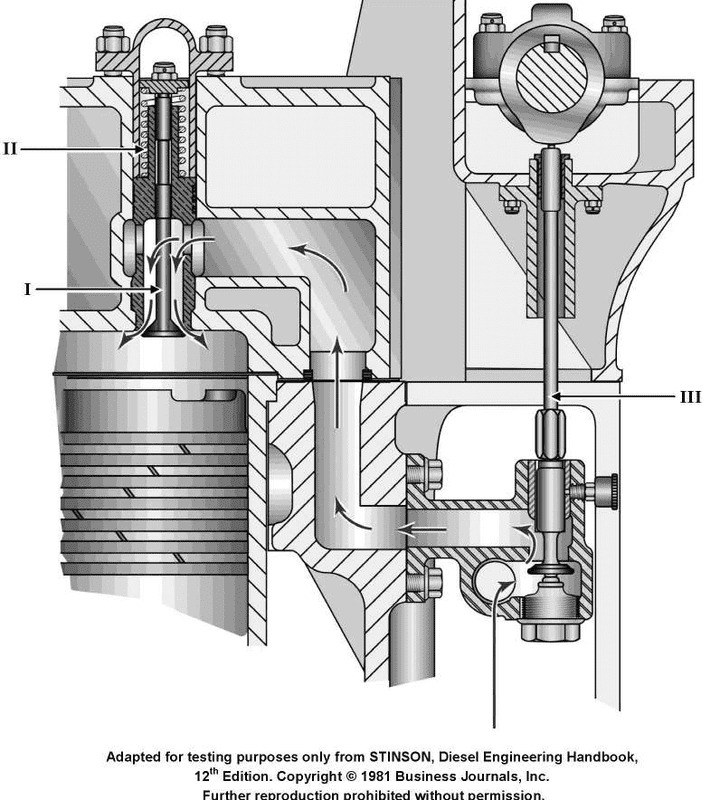
Question: Which of the following statements is true concerning the air starting valve, labeled "III", as shown in the illustration? Illustration MO-0046
A. During normal engine running, the air starting valve opens and closes constantly due to cam action.
B. The air starting valve is opened by cam action.
C. When starting air is secured, the air starting valve is closed.
D. When starting, the air starting valve is held open by air pressure.
The correct answer is B) The air starting valve is opened by cam action. The air starting valve, labeled "III" in the illustration, is a component in the engine's air starting system. This valve is responsible for allowing compressed air to enter the engine cylinder to facilitate starting. During normal engine operation, the air starting valve is not constantly opening and closing, as described in option A. When the engine is being started, the air starting valve is opened by the cam action of the engine, allowing the compressed air to flow into the cylinder and crank the engine. This makes option B the correct answer. Options C and D are incorrect, as the air starting valve is not closed when starting air is secured, nor is it held open by air pressure during the starting process.
Question 187
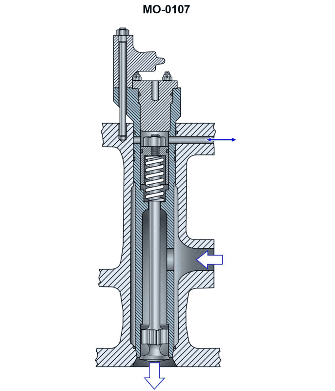
Question: In a direct cylinder admission air starting system, once the engine begins to fire, the air starting check valve illustrated, is closed by_______________. Illustration MO-0107
A. the starting air pressure
B. the spring force and cylinder pressure
C. a valve actuating cam
D. a pneumatic bellows assembly
The correct answer is B) the spring force and cylinder pressure. In a direct cylinder admission air starting system, once the engine begins to fire, the air starting check valve is closed by the spring force and the increasing cylinder pressure. As the engine starts, the cylinder pressure rises, which, combined with the spring force, pushes the check valve closed to prevent the air pressure from flowing back into the starting air system. This ensures that the engine can continue running on its own power without the need for the starting air supply. The other options are incorrect because: A) the starting air pressure alone does not close the valve, B) the spring force and cylinder pressure are the correct mechanism, C) a valve actuating cam is not involved in this process, and D) a pneumatic bellows assembly is not part of the direct cylinder admission air starting system.
Question 205
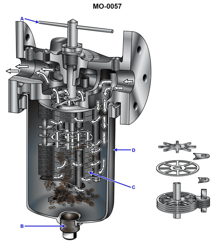
Question: How is the illustrated strainer element cleaned during engine operation? Illustration MO-0057
A. The drain plug is removed and the housing is drained.
B. The housing is removed and the element is cleaned with a solvent.
C. The T-handle is rotated.
D. The strainer element is removed, cleaned in kerosene or solvent, and dried with an air brush.
The correct answer is C) The T-handle is rotated. The illustrated strainer element is typically cleaned during engine operation by rotating the T-handle on the strainer housing. This allows the strainer element to be cleaned without shutting down the engine or removing the housing. Rotating the T-handle opens the strainer to the flow of fuel or oil, allowing contaminants to be flushed out while the engine is running. This is the standard procedure for cleaning this type of strainer element without disassembly. The other answer choices are incorrect because they describe more involved procedures that would require shutting down the engine. Draining the housing (A) or fully removing and cleaning the element (B, D) are not the typical method for cleaning this type of strainer during normal engine operation.
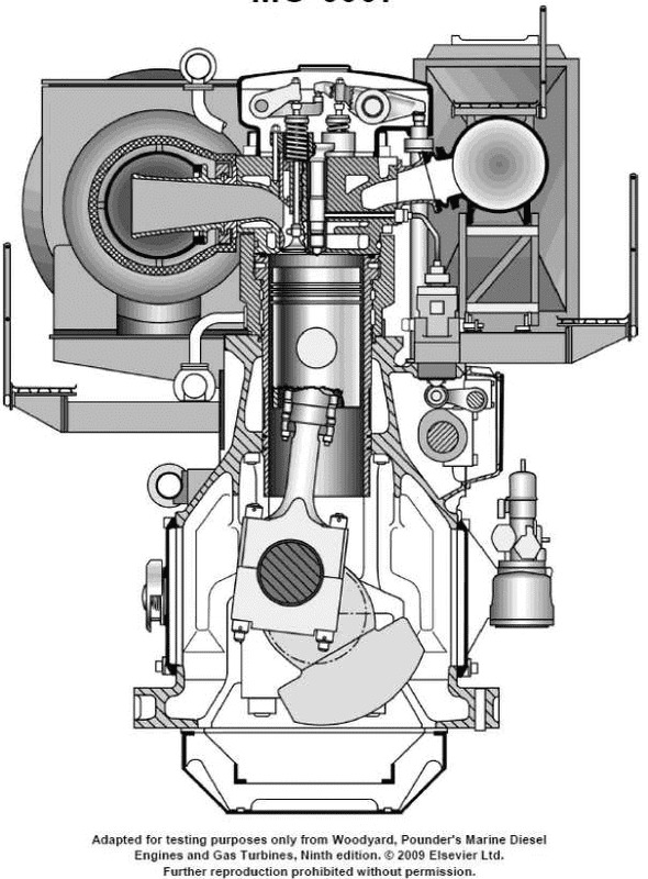
Question 221
Question: According to the diagram shown in the illustration, the lube oil system can best be described as a_______________. Illustration MO-0007
A. bypass system
B. dry sump system
C. wet sump system
D. shunt system
The correct answer is C) wet sump system. A wet sump system is a type of lubrication system where the oil is stored in a sump or reservoir at the bottom of the engine. This system uses a pump to draw oil from the sump and circulate it through the engine, allowing it to lubricate the various components. The illustration MO-0007 depicts a wet sump system, which is the most common type of lubrication system used in marine engines. The other options are incorrect because: A) A bypass system is a type of filtration system, not a lubrication system. B) A dry sump system has the oil stored in a separate tank, not in the engine sump. D) A shunt system is not a recognized type of lubrication system.
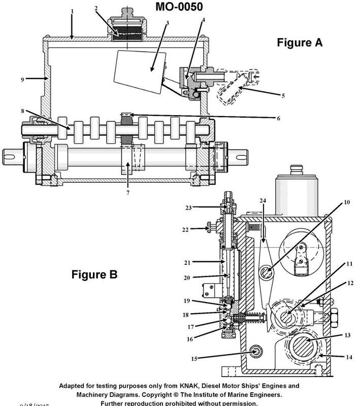
Question 239
Question: The illustrated device is used to_______________. Illustration MO-0050
A. supply cylinder lubricating oil to the engine
B. meter fuel oil to the injectors
C. admit the correct amount of starting air to the cylinders in proper order
D. actuate exhaust valves in the correct sequence
The correct answer is A) supply cylinder lubricating oil to the engine. This device is likely a lubricating oil pump, which is used to supply the necessary lubrication to the engine cylinders and other moving parts. Proper lubrication is critical for the safe and efficient operation of the engine, as it reduces wear and tear on the components. The other answer choices are incorrect because they describe different engine systems - B) is for the fuel system, C) is for the starting air system, and D) is for the exhaust valve actuation, which are not the function of the illustrated device.
Question 240
Question: The component labeled as part No.20 in the illustration is used to_______________. Illustration MO-0050
A. meter the amount of oil flow to the cylinder lubricating quill
B. adjust the timing of the cylinder lubricating oil to the cylinder
C. indicate the quantity of oil flow to the cylinder
D. prevent the backflow of oil and combustion gases
The correct answer is C) indicate the quantity of oil flow to the cylinder. The component labeled as part No.20 in the illustration MO-0050 is likely an oil flow meter or indicator. Its primary function is to measure and display the amount of lubricating oil being supplied to the cylinder, allowing the operator to monitor and adjust the oil flow as needed. This is an important component for ensuring proper lubrication and preventing excessive or insufficient oil supply to the cylinder. The other answer choices are incorrect because they do not accurately describe the primary function of this component. Option A refers to metering the oil flow, which is a different function from indicating the flow. Option B is about adjusting the timing of the oil supply, which is not the main purpose of this particular component. Option D is about preventing backflow, which is not the primary function either.
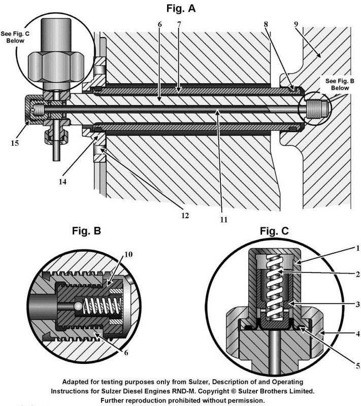
Question 245
Question: The device shown in figure "A" of the illustration is used to_______________. Illustration MO-0042
A. inject fuel into the cylinder
B. admit starting air to the cylinder
C. provide lubrication to the cylinder
D. provide an adapter to obtain combustion pressure readings
The correct answer is C) provide lubrication to the cylinder. The device shown in figure "A" of the illustration MO-0042 is likely a lubricator, which is used to provide lubrication to the cylinder of an engine. Proper lubrication is essential for the smooth and efficient operation of an engine, as it reduces friction and wear on the moving parts. The lubricator ensures that the necessary amount of oil or grease is supplied to the cylinder, which is crucial for maintaining the engine's performance and longevity. The other answer choices are incorrect because they do not accurately describe the function of the device shown in the illustration. Options A and B are related to fuel and air supply, respectively, while option D is for obtaining combustion pressure readings, which is not the purpose of the device depicted.
Question 246
Question: The device shown in the illustration is classified as a/an _______________. Illustration MO-0008
A. comparator type mist detector
B. exhaust gas vapor condenser
C. Ringelmann exhaust gas analyzer
D. reflective type explosion meter
The correct answer is A) comparator type mist detector. This is the correct answer because a comparator type mist detector is a device used to detect the presence and concentration of mist or fog in a system, which is likely what is being depicted in the illustration MO-0008. Comparator type mist detectors work by comparing the opacity of a sample to a known reference, allowing the concentration of the mist or fog to be determined. The other answer choices, such as an exhaust gas vapor condenser, Ringelmann exhaust gas analyzer, or reflective type explosion meter, are not relevant to the illustration and would not be the correct classification for the device shown.
Question 247
Question: The device shown in the illustration is a_______________. Illustration MO-0008
A. rotary type mist detector, designed for use in four-stroke, high-speed diesel engines
B. photoelectric, explosive gas indicator, for use in high-speed, two-stroke, trunk type piston engines
C. comparator type mist detector for large low-speed, crosshead type engines
D. level type explosimeter, for small medium-speed, trunk type piston engines
The correct answer is C) comparator type mist detector for large low-speed, crosshead type engines. This is the correct answer because the device shown in the illustration, MO-0008, is a comparator type mist detector, which is typically used in large, low-speed, crosshead type engines. Comparator type mist detectors are designed to monitor the oil mist concentration in the crankcase of these types of engines to detect potential lubrication issues. The other answer choices describe different types of devices that are not applicable to the device shown in the illustration. For example, option A describes a rotary type mist detector for high-speed diesel engines, while option B describes a photoelectric, explosive gas indicator for two-stroke, trunk type piston engines. Option D refers to a level type explosimeter for small, medium-speed, trunk type piston engines, which is also not the correct device.
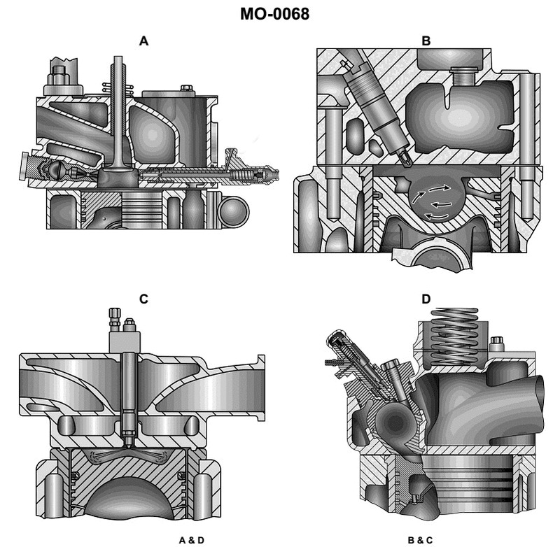
Question 253
Question: Which of the combustion chambers shown in the illustration is referred to as an "energy cell" used in some small diesel engines? Illustration MO-0068
A. A
B. B
C. C
D. D
The correct answer is A. The combustion chamber labeled as "A" in the illustration MO-0068 is referred to as an "energy cell" used in some small diesel engines. This term is commonly used to describe the compact, high-efficiency combustion chamber design found in certain lightweight and high-speed diesel engines, particularly those used in marine and off-highway applications. The other options (B, C, and D) represent different combustion chamber designs that are not specifically referred to as "energy cells" in the context of small diesel engines.
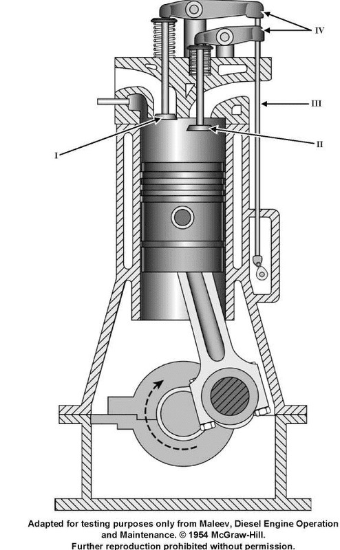
Question 261
Question: The combustion of fuel for the illustrated engine is initiated by_______________. Illustration MO-0020
A. fuel injection provided by a unit injector
B. individual Bosch fuel pumps
C. a spray of fuel into a turbulence combustion chamber
D. fuel sprayed into an energy cell
The correct answer is C) a spray of fuel into a turbulence combustion chamber. This is correct because the illustration MO-0020 likely depicts a diesel engine, where the combustion of fuel is initiated by spraying fuel into a turbulence combustion chamber. This process allows for efficient mixing of the fuel and air, leading to complete combustion. The other answer choices are incorrect because: A) fuel injection using a unit injector is more common in modern high-speed diesel engines, B) individual Bosch fuel pumps are used to supply fuel to the injectors, and D) an "energy cell" is not a standard component of a diesel engine's combustion system.
Question 262
Question: Which of the listed types of precombustion chambers is used in the diesel engine shown in the illustration? Illustration MO-0007
A. Turbulence chamber
B. Energy cell
C. Common rail
D. Open type
The correct answer is A) Turbulence chamber. The turbulence chamber is the type of precombustion chamber used in the diesel engine shown in the illustration MO-0007. This is because turbulence chambers are a common design for the precombustion chambers in medium-speed and high-speed diesel engines, which are commonly used in maritime applications like those overseen by the US Coast Guard. The other answer choices are not correct because: B) Energy cell is not a standard type of precombustion chamber, C) Common rail is a fuel injection system rather than a precombustion chamber design, and D) Open type precombustion chambers are less common in modern diesel engines.
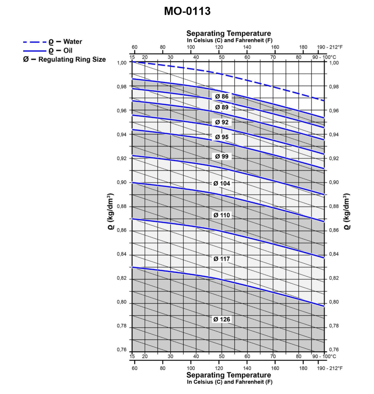
Question 269
Question: If a particular liquid has a specific gravity of 0.96 kg/dm3 at 77°F, what will be the specific gravity of the liquid, as determined from the graph shown in the illustration, if the temperature is increased to 167°F? Illustration MO-0113
A. 0.910 kg/dm3
B. 0.915 kg/dm3
C. 0.920 kg/dm3
D. 0.925 kg/dm3
The correct answer is D) 0.925 kg/dm3. The key to solving this problem is understanding how temperature affects the specific gravity of a liquid. As the temperature of a liquid increases, its specific gravity decreases. The graph provided in the illustration MO-0113 shows the relationship between temperature and specific gravity for this particular liquid. Given that the specific gravity of the liquid is 0.96 kg/dm3 at 77°F, and the temperature is increased to 167°F, the specific gravity can be determined from the graph to be 0.925 kg/dm3, which corresponds to answer choice D. The other answer choices are incorrect because they do not match the value indicated by the graph for the increased temperature of 167°F.
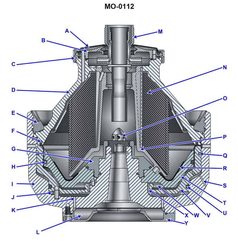
Question 274
Question: The device labeled "D", as shown in the illustration, is the bowl _______________. Illustration MO-0112
A. hood
B. top
C. cover
D. hub
The correct answer is B) top. The device labeled "D" in the illustration MO-0112 is the bowl top, which is the cover or lid of the bowl component of the device. The other answer choices are incorrect because: A) "hood" is not an accurate term for this component of the device. C) "cover" is too general and does not specifically describe the top or lid of the bowl. D) "hub" is not the correct term for this part of the device.
Question 275
Question: The discharge nozzle shown in the illustration, is indicated by the letter . Illustration MO-0112
A. A
B. K
C. S
D. X
The correct answer is C) S. The illustration MO-0112 is likely depicting components of a fire suppression system, and the letter 'S' is commonly used to indicate the discharge nozzle in such illustrations. The discharge nozzle is the component responsible for dispersing the fire suppression agent (e.g., water, foam, or dry chemical) onto the fire, making it a critical part of the system. The other answer choices (A, B, D) do not typically represent the discharge nozzle in these types of illustrations, which is why C) S is the correct answer.
Question 276
Question: The device labeled "B", shown in the illustration is known as the _______________. Illustration MO-0112
A. upper ring chamber
B. set of regulating rings
C. comminuting device
D. centripetal pump chamber cover
The correct answer is D) centripetal pump chamber cover. The device labeled "B" in the illustration MO-0112 is the centripetal pump chamber cover. This is the cover that encloses the centripetal pump, which is a type of pump used in various marine applications, including in the US Coast Guard. The centripetal pump chamber cover helps to protect and enclose the internal components of the pump. The other answer choices are incorrect because they do not accurately describe the device labeled "B" in the given illustration. The upper ring chamber, set of regulating rings, and comminuting device are different components that are not depicted in this particular illustration.
Question 277
Question: The area indicated by the letter "L" of the device shown in the illustration is properly called the _______________. Illustration MO-0112
A. pre-injection chamber
B. operating water reservoir
C. channeling chamber
D. injection chamber
The correct answer is D) injection chamber. The illustration MO-0112 is likely depicting a fuel injection system, and the area indicated by the letter "L" is the injection chamber where the fuel is injected into the engine. This is the correct terminology as the injection chamber is the specific part of the fuel injection system responsible for delivering the fuel to the engine. The other answer choices are not accurate. The pre-injection chamber, operating water reservoir, and channeling chamber are not the proper terms for the area indicated by "L" in this type of fuel injection system illustration.
Question 278
Question: The unit shown in the illustration is beginning the sludge discharge cycle. The operating liquid solenoid valve has been energized and space "J" is filling up. Which of the following actions should occur next? Illustration MO-0112
A. The liquid enters the opening space, controlled by the discharge port "S", thereby causing the sliding bowl bottom to move upwards.
B. The liquid enters via port "X" into the opening space with the net resultant force causing the piston slide to move down.
C. The liquid enters via port "X", travels through the closing chamber, and exits port "S", maintaining an upward force against the bowl bottom.
D. The liquid remains trapped in space "J", developing an upward force to open the bowl.
The correct answer is B. When the liquid solenoid valve is energized, the liquid enters via port "X" into the opening space. This creates a net resultant force that causes the piston slide to move down, initiating the sludge discharge cycle. Option A is incorrect because the sliding bowl bottom does not move upwards during this stage of the cycle. Option C is incorrect because the liquid does not exit through port "S" at this point. Option D is incorrect because the liquid is not trapped in space "J"; instead, it is being used to create the downward force on the piston slide.
Question 279
Question: The gasket "U" shown in the illustration, is used to seal the liquid space below the _______________. Illustration MO-0112
A. ring dam
B. inner bowl
C. outer bowl
D. sliding piston
The correct answer is D) sliding piston. The gasket "U" shown in the illustration MO-0112 is used to seal the liquid space below the sliding piston. The sliding piston is a key component in many mechanical devices, and ensuring a proper seal around it is crucial to prevent leaks and maintain the intended function of the system. The other answer choices are incorrect because they do not accurately describe the component that the gasket "U" is sealing. The ring dam, inner bowl, and outer bowl are different parts of the overall mechanical assembly, but they are not the specific component that the gasket "U" is designed to seal.
Question 280
Question: The device labeled "H", shown in the illustration is referred to as the _. Illustration MO-0112
A. upper chamber bowl gasket
B. centrifugation chamber bottom gasket
C. sliding piston upper seal
D. sliding piston lower seal
The correct answer is B) centrifugation chamber bottom gasket. The device labeled "H" in the illustration MO-0112 is the centrifugation chamber bottom gasket, which is responsible for sealing the bottom of the centrifugation chamber and preventing leaks. This component is critical in maintaining the proper functioning of the centrifugation process, as it ensures that the fluid being processed remains contained within the chamber. The other answer choices are incorrect because they do not accurately describe the function or location of the device labeled "H" in the given illustration. The upper chamber bowl gasket, sliding piston upper seal, and sliding piston lower seal are not the components being referred to in this question.
Question 281
Question: The device labeled 'C' shown in the illustration is known as the _______________. Illustration MO-0112
A. upper locking ring
B. lower paring device
C. upper paring gasket
D. pump lock
The correct answer is A) upper locking ring. The device labeled 'C' in the illustration MO-0112 is the upper locking ring, which is a component used to secure the upper paring device in place. The upper locking ring is responsible for keeping the upper paring device stationary and preventing it from moving during operation. The other answer choices are incorrect because: B) lower paring device refers to a different component, C) upper paring gasket is a separate sealing component, and D) pump lock is not a term associated with the device shown in the illustration.
Question 282
Question: Where does the shoot cycle operating liquid first come in contact with the rotating forces of the device shown in the illustration? Illustration MO-0112
A. While traveling under disc stack "N".
B. At the inlet cone labeled "O".
C. In the opening chamber labeled "L".
D. At the inlet orifice labeled "S".
The correct answer is C. In the illustration MO-0112, the shoot cycle operating liquid first comes in contact with the rotating forces of the device in the opening chamber labeled "L". This is the correct answer because the operating liquid enters the device through the inlet cone labeled "O", and then flows into the opening chamber labeled "L" where it encounters the rotating forces of the device. The other options are incorrect because the liquid does not come into contact with the rotating forces under the disc stack "N" (option A), at the inlet orifice labeled "S" (option D), or at any other location in the device.
Question 283
Question: What is used as the primary operating medium during the sludge discharge cycle, shown in the illustration? Illustration MO-0112
A. Light phase liquid
B. Heavy phase liquid
C. Hydraulic fluid
D. Water
The correct answer is D) Water. During the sludge discharge cycle, water is typically used as the primary operating medium. This is because water is an abundant, readily available, and inexpensive fluid that can effectively facilitate the movement and discharge of sludge from the system. The other options are not correct because: A) Light phase liquid and B) Heavy phase liquid are not commonly used as the primary operating medium for sludge discharge, and C) Hydraulic fluid is typically reserved for more specialized hydraulic systems, not for general sludge discharge operations.
Question 284
Question: The item indicated by the letter "F" of the device shown in the illustration is the . Illustration MO-0112
A. guide band
B. guide pin
C. locating dowel pin
D. upper bowl gasket
The correct answer is D) upper bowl gasket. The illustration MO-0112 is likely showing a device or component related to the US Coast Guard Captain's License Examinations. The item indicated by the letter "F" is the upper bowl gasket, which is a sealing element used to prevent leaks in the device. The other answer choices are not correct because: A) the guide band is a different component, B) the guide pin is also a different component, and C) the locating dowel pin is not the item indicated by "F" in the illustration.
Question 285
Question: What terminates the sludge discharge cycle of the device shown in the illustration? Illustration MO-0112
A. The solenoid valve opens, directs high-pressure fluid into the closing chamber, and results in an upward movement of the sliding piston.
B. The solenoid valve closes, reduces the water pressure to the paring chamber, and allows the spring force to move the sliding piston upward.
C. The solenoid valve closes, allows the water in the opening chamber to bleed off through "S", and the sliding piston moves upward due to the force developed in area "J".
D. The solenoid valve closes, allows the weight of the sliding piston to oppose the low water pressure, and moves it along the axis of the spindle.
The correct answer is C) The solenoid valve closes, allows the water in the opening chamber to bleed off through "S", and the sliding piston moves upward due to the force developed in area "J". This is the correct answer because when the solenoid valve closes, it stops the high-pressure water from entering the opening chamber. This allows the water in the opening chamber to bleed off through the "S" port, reducing the pressure in that chamber. The force developed in area "J" then causes the sliding piston to move upward, terminating the sludge discharge cycle. The other options are incorrect because they do not accurately describe the mechanism that terminates the sludge discharge cycle. Option A describes the valve opening to initiate the cycle, not terminate it. Options B and D do not accurately explain the forces and pressure changes that lead to the upward movement of the sliding piston.
Question 286
Question: The port "X" shown in the illustration allows water to enter the adjoining chamber. During what cycle of operation will this occur? Illustration MO-0112
A. Operating backflush cycle
B. Bowl retention cycle
C. Clarification cycle
D. Sludge discharge cycle
The correct answer is D) Sludge discharge cycle. During the sludge discharge cycle, the port "X" shown in the illustration allows water to enter the adjoining chamber. This is because the sludge discharge cycle is designed to expel accumulated sludge from the separator, and the port "X" facilitates this process by allowing water to enter and flush out the sludge. The other answer choices are incorrect because they do not relate to the sludge discharge cycle. The operating backflush cycle, bowl retention cycle, and clarification cycle do not involve the specific function of the port "X" as described in the question.
Question 287
Question: The wear liner shown in the illustration is indicated by the letter_______________. Illustration MO-0112
A. "G"
B. "N"
C. "P"
D. "R"
The correct answer is D) "R". The wear liner shown in the illustration MO-0112 is indicated by the letter "R". This is the correct answer based on the standard labeling and identification of components in marine engine illustrations and schematics. The other answer choices are incorrect because: A) "G" likely refers to a different component, not the wear liner. B) "N" is not used to indicate the wear liner in this illustration. C) "P" is also not the label used for the wear liner in this particular diagram.
Question 288
Question: The force developed by the liquid within space "J" of the device shown in the illustration depends upon_______________. Illustration MO-0112
A. the speed of the bowl and the condition of seal "H"
B. the angular velocity at which the liquid travels
C. the speed of the bowl and the condition of seal "U"
D. inertia forces during starting and stopping
The correct answer is C) the speed of the bowl and the condition of seal "U". The force developed by the liquid within space "J" of the device shown in the illustration depends on the speed of the bowl and the condition of the seal "U". As the bowl rotates at a certain speed, the liquid inside the bowl is subjected to centrifugal force, which creates a pressure difference between the inner and outer regions of the bowl. This pressure difference, in turn, depends on the speed of the bowl and the condition of the seal "U", which helps maintain the pressure differential. The other answer choices are incorrect because they do not accurately describe the factors that influence the force developed by the liquid within space "J".
Question 289
Question: The area indicated by the letter "W", shown in the illustration is correctly termed the_______________. Illustration MO-0112
A. closing chamber
B. parting chamber
C. upper sliding piston chamber
D. opening chamber
The correct answer is D) opening chamber. The opening chamber, indicated by the letter "W" in the illustration MO-0112, is the correct term for this part of the mechanism. This is because the opening chamber is where the piston moves to open the valve, allowing the flow of fluid or gas through the system. The other answer choices are not accurate terms for this specific component. The closing chamber, parting chamber, and upper sliding piston chamber do not accurately describe the function and location of the component labeled "W" in the illustration.
Question 290
Question: The device labeled "A", shown in the illustration, is known as the_______________. Illustration MO-0112
A. centripetal pump cover
B. bowl assembly hood
C. regulating ring
D. kinetic converter
The correct answer is C) regulating ring. The regulating ring is a device that is used to control the flow and pressure of fluids in various marine and industrial applications. In the context of the illustration MO-0112, the device labeled "A" is likely a regulating ring that is used to regulate the flow or pressure of a specific fluid or substance. The other answer choices are incorrect because they do not accurately describe the function or purpose of the device labeled "A" in the illustration. A centripetal pump cover, a bowl assembly hood, and a kinetic converter are all different types of components or devices that serve different purposes in various systems, and they do not match the description of the device shown in the illustration.
Question 291
Question: During normal operation, the liquid retained in space 'J' of the device shown in the illustration is_______________. Illustration MO-0112
A. directly forcing the sliding piston upward to keep the bowl closed
B. maintaining the bowl oil/water seal interface
C. lubricating the shaft bearings
D. maintaining oil pump pressure
The correct answer is A) directly forcing the sliding piston upward to keep the bowl closed. The liquid retained in space 'J' of the device shown in the illustration is used to apply upward force on the sliding piston, which in turn keeps the bowl closed during normal operation. This is a key function of the device to maintain its proper separation and containment capabilities. The other answer choices are incorrect because they do not accurately describe the primary purpose of the liquid in space 'J'. Options B, C, and D describe secondary functions that may be present, but are not the main role of the liquid in this specific part of the device.
Question 292
Question: Item "O" of the device shown in the illustration is the_______________. MO-0112
A. fair flow nut
B. inlet directional guide
C. spindle nut
D. impeller locking device
The correct answer is C) spindle nut. The spindle nut, labeled as item "O" in the illustration, is responsible for securing the impeller in place within the device. This is a critical component that ensures the proper and safe operation of the equipment. The other answer choices are incorrect because: A) A fair flow nut is not a component typically found in this type of device. B) The inlet directional guide is a separate component, likely labeled with a different letter. D) The impeller locking device is a different mechanism used to secure the impeller, distinct from the spindle nut.
Question 293
Question: Which of the following statements describes "N" shown in the illustration? Illustration MO-0112
A. the included angle of oil flow
B. the centrifuge disc stack
C. the sole direction of heavy phase flow
D. the relative size of the separation zone
The correct answer is B) the centrifuge disc stack. The illustration MO-0112 likely depicts a centrifuge used for oil-water separation, and the "N" symbol represents the centrifuge disc stack, which is a key component of the centrifuge. The disc stack is responsible for creating the centrifugal force that separates the oil and water phases within the centrifuge. The other answer choices are incorrect because they do not accurately describe the "N" symbol in the context of a centrifuge used for oil-water separation. Options A, C, and D do not directly correspond to the components or operation of a centrifuge as shown in the illustration.
Question 294
Question: During the normal operation of the centrifuge shown in the illustration, the operating liquid solenoid and bypass valves for the cleaning cycle should be in which position? Illustration MO-0112
A. The solenoid valve is closed and the bypass valve is open.
B. The solenoid valve is closed and the bypass valve is closed.
C. The solenoid valve is open and the bypass valve is closed.
D. The solenoid valve is open and the bypass valve is open.
The correct answer is B) The solenoid valve is closed and the bypass valve is closed. During the normal operation of the centrifuge, the operating liquid solenoid valve should be closed to prevent liquid from entering the centrifuge, and the bypass valve should also be closed to ensure that the liquid is properly processed through the centrifuge. This configuration ensures that the centrifuge operates as intended, with the liquid being separated or cleaned without any bypassing or leakage. The other options are incorrect because they do not properly describe the correct valve positions for the normal operation of the centrifuge. For example, having the solenoid valve open and the bypass valve closed (option C) would allow liquid to enter the centrifuge, while having both valves open (option D) would allow the liquid to bypass the centrifuge altogether.
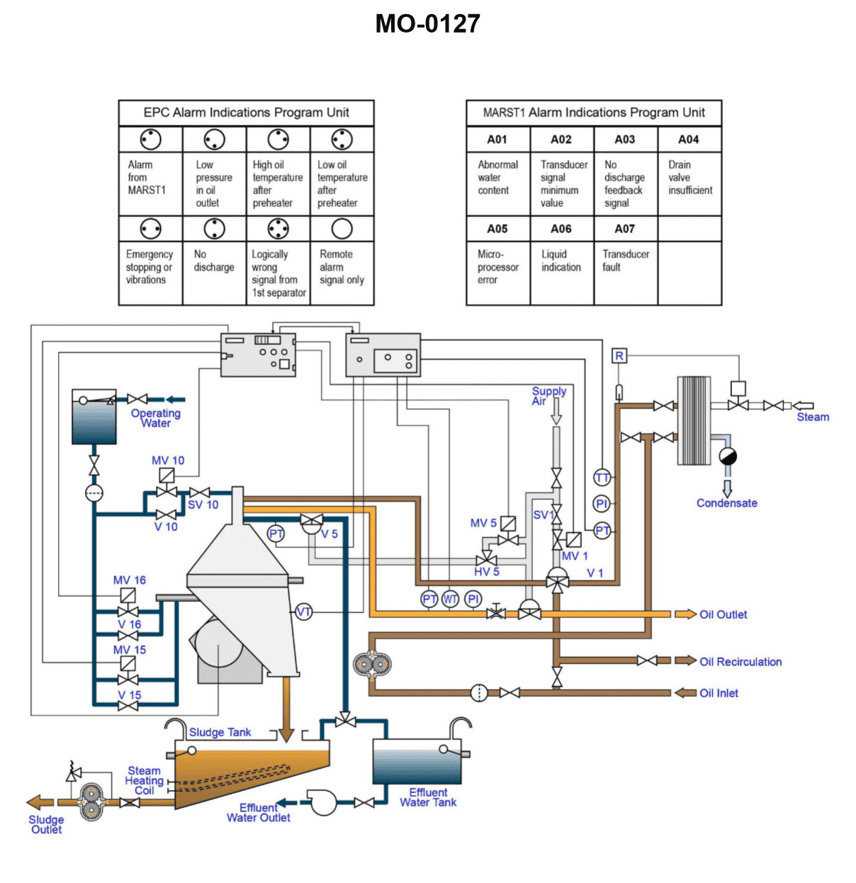
Question 297
Question: Which of the following precautions should be taken prior to starting the separator shown in the illustration? Illustration MO-0127
A. Make sure the separator is properly assembled.
B. Check for the correct oil level in the gear housing.
C. Release the bowl brake and confirm proper valve line up.
D. All of the above are correct.
The correct answer is D) All of the above are correct. This is the correct answer because all three precautions are necessary to safely start the separator shown in the illustration: 1) Making sure the separator is properly assembled ensures it is in good working order and will function as intended. 2) Checking the correct oil level in the gear housing is critical to proper lubrication and preventing damage to the separator. 3) Releasing the bowl brake and confirming proper valve line-up prepares the separator for safe start-up and operation. The other options are incorrect because they do not encompass all the necessary precautions that should be taken prior to starting the separator.
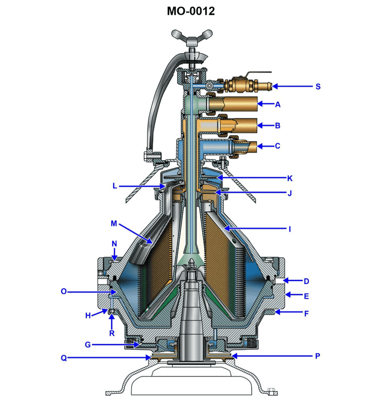
Question 298
Question: The device shown in the illustration can be automatically or manually desludged. The closing sequence at the end of the desludging cycle is initiated by opening which of the labeled components listed below? Illustration MO-0012
A. F
B. P
C. Q
D. R
The correct answer is C) Q. The closing sequence at the end of the desludging cycle is initiated by opening the component labeled Q. This is because Q is the valve that controls the opening and closing of the desludging cycle. By opening Q, the system is able to complete the desludging process and return to its normal operating state. The other options are incorrect because F, P, and R are not the components responsible for initiating the closing sequence of the desludging cycle. They likely serve other functions within the overall system, but do not directly control the completion of the desludging process.
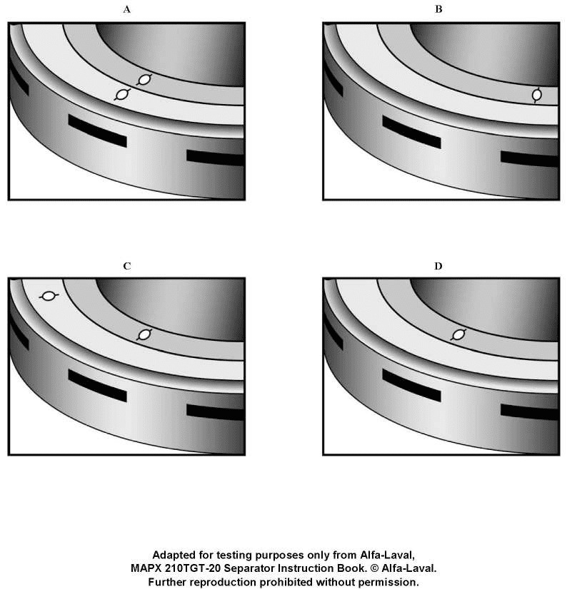
Question 299
Question: Which of the labeled figures illustrated, represents the correct alignment mark relationships of a properly reassembled centrifuge bowl? Illustration MO-0022
A. A
B. B
C. C
D. D
The correct answer is A. The alignment mark relationships of a properly reassembled centrifuge bowl are depicted in figure A. The alignment marks on the various components must be properly matched up to ensure the centrifuge is reassembled correctly and can operate safely. Figure A shows the correct alignment of these marks, while the other options do not represent the proper reassembly configuration. The alignment of these marks is a critical safety requirement specified in the operating procedures and maintenance manuals for centrifuge equipment. Failure to properly reassemble the centrifuge could lead to imbalance, vibration, or even catastrophic failure during operation, posing serious risks. Therefore, figure A is the correct representation of the proper alignment marks for a reassembled centrifuge bowl.
Question 300
Question: In the device shown in the illustration, the component lettered "A" is the_______________. Illustration MO-0012
A. seal water input port
B. heavy phase discharge port
C. light phase discharge port
D. dirty oil input port
The correct answer is D) dirty oil input port. This is because in the device shown in the illustration MO-0012, the component lettered "A" is the dirty oil input port where the contaminated oil enters the device for processing and separation. The other answer choices are incorrect because: A) is not the function of the component lettered "A", B) and C) refer to the discharge ports for the separated heavy and light phases, respectively, which are different components in the device.
Question 301
Question: How is oil supplied to the device shown in the illustration? Illustration MO-0127
A. An attached positive displacement pump supplies oil to the separator.
B. In this arrangement an independent pump is utilized.
C. The oil inlet paring disc creates a low-pressure in the suction piping.
D. This purifier as well as most others will be installed in the lower engine room to make use of gravitational forces.
The correct answer is B) In this arrangement an independent pump is utilized. The explanation is as follows: 1) Confirm the correct answer: B is the correct answer. 2) Explanation of the reasoning: In a typical oil purifier system, an independent pump is used to supply oil to the purifier device. This pump ensures that the oil is circulated through the purifier at the appropriate flow rate and pressure, which is necessary for the proper operation of the separation process. 3) Explanation of why other options are incorrect: Option A is incorrect because the purifier does not have an attached positive displacement pump - it relies on a separate, independent pump. Option C is incorrect because the low-pressure in the suction piping is not the mechanism that supplies oil to the purifier. Option D is incorrect because the location of the purifier in the engine room does not determine how the oil is supplied to the device. 4) Concise summary: The correct answer is B because an independent pump, separate from the purifier, is used to supply oil to the oil purifier device.
Question 302
Question: Which of the following statements represents the working principle of the water transducer used with the separator shown in the illustration? Illustration MO-0127
A. The capacitor completes part of the inductive circuit which monitors pressure changes.
B. The probe and sensor measure the dielectric constant through capacitive reactance of the process fluid.
C. As the water content in the oil decreases, the dielectric constant increases.
D. All of the above are correct.
The correct answer is B) The probe and sensor measure the dielectric constant through capacitive reactance of the process fluid. The water transducer in the separator system uses a capacitance-based measurement principle to detect the water content in the oil. As the water content in the oil changes, the dielectric constant of the fluid also changes. The probe and sensor in the transducer measure this change in dielectric constant through capacitive reactance, which allows the system to determine the water content. This is the working principle of the water transducer. The other options are incorrect because they do not accurately describe the working principle of the capacitive water transducer. Option A is incorrect as it describes an inductive circuit, while option C is incorrect as it states the relationship between water content and dielectric constant is opposite to the actual behavior.
Question 303
Question: Which of the following statements is accurate concerning the vibration sensing device used with the separator shown in the illustration? Illustration MO-0127
A. Vibration sensors are not used with centrifuges currently installed on diesel vessels due to excessive vibrations developed by the main propulsion units.
B. The vibration switch is sensitive to vibration in a direction horizontal to its mounting base and is normally installed low on the separator where movement is magnified.
C. The detector mechanism consists of an armature suspended on a flexure pivot and restrained from motion by a permanent magnet acting through a small air gap.
D. The detector is so arranged to prevent abnormal harmonic frequencies from being developed while the separator is passing through its critical speed range.
The correct answer is C. The explanation is as follows: 1. Confirm the correct answer: The correct answer is C) The detector mechanism consists of an armature suspended on a flexure pivot and restrained from motion by a permanent magnet acting through a small air gap. 2. Explain the reasoning: This description accurately depicts the typical vibration sensing device used with centrifugal separators on diesel vessels. The armature suspended on a flexure pivot and the permanent magnet restraint are the key components that allow the detector to sense abnormal vibrations and trigger an alarm or automatic shutdown. 3. Explain why the other options are incorrect: Option A is incorrect as vibration sensors are commonly used with centrifuges on diesel vessels. Option B is incorrect as the vibration switch is typically mounted to detect vertical vibrations, not horizontal. Option D is incorrect as the detector's purpose is to sense abnormal vibrations, not prevent critical speed range issues. 4. Concise explanation: The correct answer C accurately describes the vibration sensing device used with centrifugal separators on diesel vessels, which consists of an armature suspended on a flexure pivot and restrained by a permanent magnet to detect abnormal vibrations.
Question 304
Question: The temperature of the contaminated fuel oil fed to the centrifuge shown in the illustration should be _______________. Illustration MO-0012
A. 160°F to 180°F
B. 203°F to less than 212°F
C. greater than 212°F
D. selected according to the oil's viscosity index
The correct answer is B) 203°F to less than 212°F. This temperature range is typically required for the contaminated fuel oil fed to a centrifuge in order to reduce the oil's viscosity and facilitate the separation of contaminants. Operating the centrifuge within this temperature range helps ensure optimal performance and efficiency in the purification process. The other options are incorrect because: A) 160°F to 180°F may be too low to achieve the necessary viscosity reduction, C) greater than 212°F could lead to excessive vaporization, and D) selecting the temperature based solely on the viscosity index would not account for other factors that influence the optimal operating temperature.
Question 305
Question: All alarms occurring on the control unit of the device shown in the illustration will_______________. Illustration MO-0127
A. shut off the oil feed to the separator
B. be initiated by the water transducer or vibration switch
C. cause the separator to automatically enter the sludge discharge cycle
D. not be indicated in numerical order
A) shut off the oil feed to the separator is the correct answer. The reasoning is that alarms occurring on the control unit of the device shown in the illustration (likely an oil/water separator) are designed to automatically shut off the oil feed to the separator in order to prevent oil discharge overboard and protect the environment. This is a standard safety feature required by Coast Guard regulations for oil/water separation equipment used on vessels. The other answer choices are incorrect because: B) the alarms would not be initiated by the water transducer or vibration switch, but rather by sensors monitoring the separation process; C) the alarms would cause a shutdown, not an automatic sludge discharge cycle; and D) the alarms would be indicated in a specific order, not randomly.
Question 306
Question: The system shown in the illustration utilizes a water transducer which is_______________. Illustration MO-0127
A. a mechanical/electrical device with a variable DC output
B. located in the oil outlet piping
C. similar to those used in sonar systems
D. essential in monitoring the amount of water entering the separator
The correct answer is B) located in the oil outlet piping. The water transducer in the illustration is used to monitor the amount of water in the oil outlet piping of the system. This is a critical component to ensure that the separator is functioning properly and not allowing excessive water to pass through with the oil. The water transducer is a sensor that can detect the presence and level of water in the outlet, allowing the system to be adjusted or shut down if necessary to prevent water contamination. The other answer choices are incorrect because: A) the water transducer is not a variable DC output device, C) it is not similar to sonar transducers, and D) while it is essential for monitoring water, it is located in the outlet piping, not the inlet.
Question 307
Question: How may water be removed from the bowl of the separator as shown in the illustration? Illustration MO-0127
A. The water may be removed through the water drain valve or through the sludge ports during the sludge discharge cycle.
B. The separator is used to remove solids from the processed liquid; therefore the accumulation of water does not present a problem.
C. When the unit is secured and the bowl stops rotating, the water is drained off the bottom of the bowl through orifice ports.
D. Water may only be removed from the bowl when the unit is secured and the bowl hood is removed.
The correct answer is A) The water may be removed through the water drain valve or through the sludge ports during the sludge discharge cycle. This is the correct answer because separator systems are designed to remove water and sludge from the processed liquid. The water that accumulates in the separator bowl can be drained through the water drain valve, and any remaining sludge can be discharged through the sludge ports during the sludge discharge cycle. The other answer choices are incorrect because B) the separator is used to remove solids, not to accumulate water, C) the water is not drained through orifice ports when the unit is secured, and D) the water can be removed without removing the bowl hood.
Question 308
Question: The greatest difference between the centrifuge bowl shown in the illustration and that of a tubular bowl, with straight, vertical, interior surfaces, is that the illustrated unit_______________. Illustration MO-0012
A. is self-desludging
B. rotates at 1000 rpm higher than the old tubular bowl type
C. rotates at 1000 rpm slower than the old tubular bowl type
D. does not require a discharge ring when operated as a separator
The correct answer is A) is self-desludging. The key difference between the centrifuge bowl shown in the illustration and a traditional tubular bowl is that the illustrated unit has a self-desludging design. This means that the solids (sludge) are automatically discharged from the bowl during operation, without the need for a separate discharge ring. This is a more efficient and convenient design compared to the older tubular bowl type, which would require manual intervention to remove the accumulated sludge. The other options are incorrect because they do not accurately describe the primary difference between the two bowl designs. The rotational speed of the bowls is not specified in the question, and the lack of a discharge ring is a feature of the self-desludging design, not a separate requirement.
Question 309
Question: The diesel engine shown in the illustration has the highest fuel pressure developed in the part labeled _______________. Illustration MO-0003
A. E
B. X
C. Y
D. Z
The correct answer is A. The part labeled "E" in the illustration is the fuel injection pump, which is responsible for developing the highest fuel pressure in the diesel engine system. The fuel injection pump is the component that pressurizes the fuel to the high levels required for injection into the engine's cylinders. The other options (X, Y, and Z) likely represent other engine components, such as the fuel lines or the engine block, which do not generate the highest fuel pressure in the system. The fuel injection pump is the critical component that creates the necessary high-pressure fuel delivery for the engine to operate effectively.
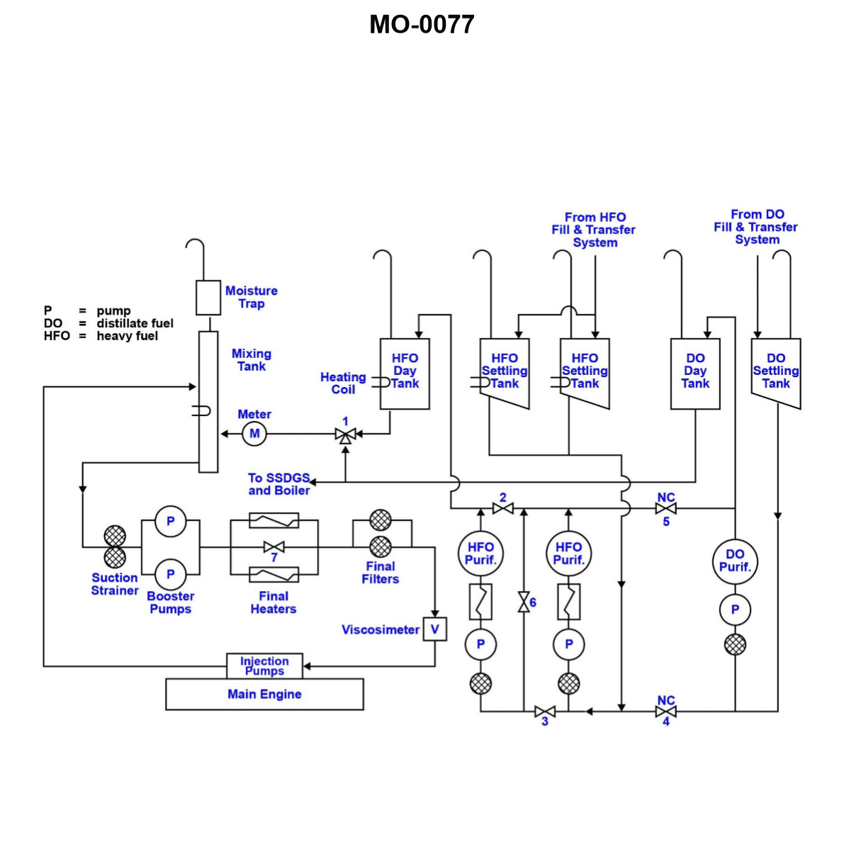
Question 311
Question: As shown in the illustration, the viscosimeter would be used to directly control the output of which of the following components? Illustration MO-0077
A. Outflow from HFO day tank.
B. Final heaters.
C. Injector pumps.
D. HFO purifiers.
The correct answer is B) Final heaters. The viscosimeter would be used to directly control the output of the final heaters. The viscosimeter measures the viscosity of the fuel, which is an important parameter for the proper operation of the final heaters. The final heaters are responsible for maintaining the fuel at the correct temperature and viscosity before it is injected into the engine. By using the viscosimeter to monitor and adjust the final heater output, the fuel can be maintained at the optimal viscosity for efficient combustion. The other answer choices are incorrect because the viscosimeter does not directly control the outflow from the HFO day tank (A), the injector pumps (C), or the HFO purifiers (D). These components have their own control systems that may use viscosity as an input, but the viscosimeter itself does not directly control their output.
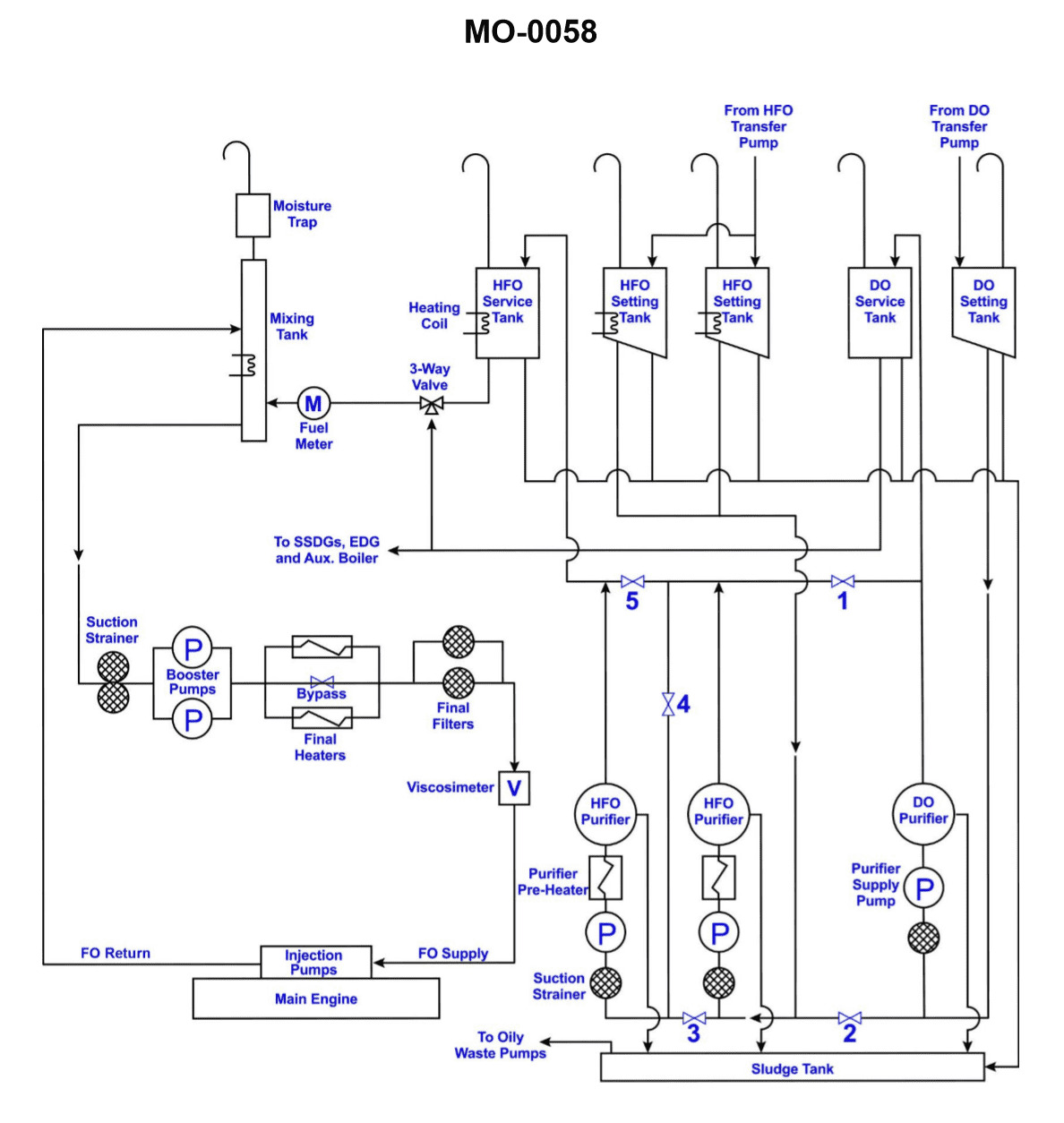
Question 312
Question: Heavy fuel oil used in the system shown in the illustration will have the lowest viscosity_______________. Illustration MO-0058
A. in the settling tank
B. at the transfer pump discharge
C. at the main engine fuel oil header
D. in the three-way valve
The correct answer is C) at the main engine fuel oil header. The viscosity of heavy fuel oil will be lowest at the main engine fuel oil header because this is the point where the fuel oil has been heated and conditioned the most. As the fuel oil travels through the system, it is typically heated to reduce its viscosity and improve its flow and atomization properties. The fuel oil will be at its lowest viscosity at the point closest to the main engine, which is the main engine fuel oil header. The other options are incorrect because the viscosity will be higher in the settling tank (A), at the transfer pump discharge (B), and in the three-way valve (D) due to the lower temperature and less conditioning of the fuel oil at these points in the system.
Question 313
Question: The purpose of the interlocked three-way valve shown in the illustration is to_______________. Illustration MO-0058
A. recirculate fuel through the heater during warm-up
B. control the rate of fuel oil flow to the engines
C. act as an emergency fuel shut off, regardless of the fuel being used
D. change fuel from heavy to light oil or vice versa while insuring that oil is returned to the proper day tank
The correct answer is D) change fuel from heavy to light oil or vice versa while ensuring that oil is returned to the proper day tank. The purpose of the interlocked three-way valve is to allow the switching of fuel types (heavy to light or vice versa) while ensuring that the fuel being switched away from is properly returned to its designated day tank. This prevents the inadvertent mixing of fuel types, which could damage the engines. The other options are incorrect because they do not fully capture the valve's primary function of facilitating fuel type changes while maintaining proper fuel routing.
Question 314
Question: If the separating temperature is to remain constant, what is the relationship between the specific gravity of the oil and the required size of the regulating ring? Illustration MO-0113
A. For a constant operating temperature, the greater the specific gravity of the oil the larger the regulating ring.
B. The specific gravity of the oil and the size of the regulating ring are related only during the initial design stages of the centrifuge.
C. With oils of greater specific viscosities it is proper to select smaller regulating rings regardless of the operating temperatures desired.
D. The larger sized regulating rings are designed to be used with oils of lower specific gravities.
The correct answer is D) The larger sized regulating rings are designed to be used with oils of lower specific gravities. The reasoning is that for a centrifugal separator to maintain a constant separating temperature, the size of the regulating ring needs to be adjusted based on the specific gravity of the oil. Oils with lower specific gravities require larger regulating rings to achieve the desired separating temperature, while oils with higher specific gravities need smaller regulating rings. This is because the size of the regulating ring impacts the flow rate and residence time of the oil in the centrifuge, which in turn affects the separating temperature. The other options are incorrect because A) is the opposite of the correct relationship, B) is not accurate as the specific gravity and regulating ring size are related during operation, not just initial design, and C) is incorrect as higher viscosity oils do not require smaller regulating rings for constant temperature operation.
Question 315
Question: Using the graph shown in the illustration, the oil being separated has a specific gravity of 0.87 kg/dm3 at 72.5°C. What will be the specific gravity if the temperature is lowered to 40°C? Illustration MO-0113
A. 0.872 kg/dm3
B. 0.882 kg/dm3
C. 0.892 kg/dm3
D. 0.902 kg/dm3
The correct answer is C) 0.892 kg/dm3. According to the graph shown in the illustration MO-0113, when the temperature of the oil is lowered from 72.5°C to 40°C, the specific gravity of the oil increases from 0.87 kg/dm3 to 0.892 kg/dm3. This is because the density of the oil increases as the temperature decreases, as per the relationship between temperature and density of liquids. The other options are incorrect because they do not accurately reflect the change in specific gravity based on the given temperature decrease, as shown in the provided graph.
Question 316
Question: From the graph shown in the illustration, if the separating temperature required is to be 167°F, and the specific gravity of the oil is 0.98 kg/dm3 at 59°F, what size regulating ring is required? Illustration MO-0113
A. 86 mm
B. 89 mm
C. 92 mm
D. 95 mm
The correct answer is C) 92 mm. The graph in the illustration MO-0113 shows the relationship between the specific gravity of the oil and the required regulating ring size to achieve a separating temperature of 167°F. Given that the specific gravity of the oil is 0.98 kg/dm3 at 59°F, the graph indicates that the required regulating ring size is 92 mm. The other answer choices are incorrect because they do not correspond to the correct regulating ring size for the provided specific gravity and separating temperature requirements, as indicated by the graph.
Question 317
Question: From the graph shown in the illustration, determine the size of the regulating ring required for the proper operation of the fuel oil centrifuge if the fuel oil specific gravity is 0.9 kg/dm3 at 68°F, and the separating temperature is 158°F. Illustration MO-0113
A. 86 mm
B. 104 mm
C. 110 mm
D. 117 mm
The correct answer is C) 110 mm. The size of the regulating ring required for the proper operation of the fuel oil centrifuge is determined by the fuel oil specific gravity and the separating temperature. The graph in the illustration shows the relationship between the regulating ring size, fuel oil specific gravity, and separating temperature. Based on the given information, with a fuel oil specific gravity of 0.9 kg/dm3 at 68°F and a separating temperature of 158°F, the correct regulating ring size is 110 mm. The other options are incorrect because they do not match the specific gravity and separating temperature values provided in the question. A regulating ring size of 110 mm is the appropriate choice for the given conditions.
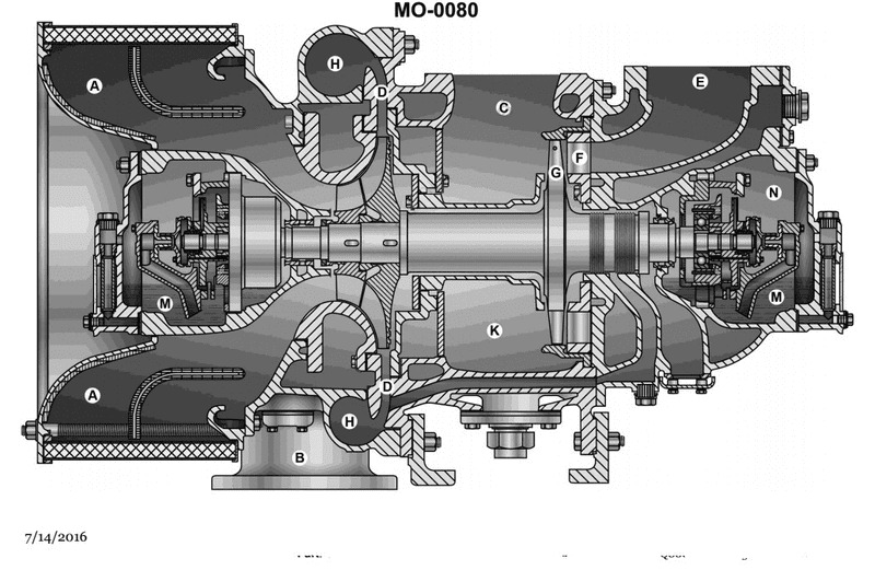
Question 323
Question: The section of the turbocharger which would be connected to the aftercooler inlet is labeled_______________. Illustration MO-0080
A. B
B. C
C. H
D. K
The correct answer is A) B. The section of the turbocharger that would be connected to the aftercooler inlet is labeled B. This is based on the illustration MO-0080, which shows the various components of a turbocharger system. The aftercooler is designed to cool the compressed air coming from the turbocharger before it enters the engine, and the connection point between the turbocharger and the aftercooler is labeled B in the illustration. The other options, C) H and D) K, represent different components of the turbocharger system, such as the turbine housing and the compressor housing, respectively, but they are not the specific section that connects to the aftercooler inlet.
Question 324
Question: Item labeled 'R' as shown in section 6 of the illustration is identified as the_______________. Illustration MO-0025
A. aftercooler
B. non-return scavenge valve
C. air filter
D. exhaust manifold
The correct answer is A) aftercooler. The aftercooler, labeled as 'R' in the illustration, is a critical component in the engine system that helps to cool the air after it has been compressed by the turbocharger. This cooling process increases the density of the air, allowing more air to enter the engine cylinders, which in turn improves engine efficiency and power output. The other options are incorrect because: B) The non-return scavenge valve is a different component that prevents the backflow of exhaust gases. C) The air filter is a separate component responsible for cleaning the intake air. D) The exhaust manifold is a different part that collects the exhaust gases from the engine cylinders.
Question 336
Question: In the engine shown in the illustration, the part labeled 'W' is cooled by _______________. Illustration MO-0003
A. lube oil
B. convection
C. air
D. sea water
The correct answer is D) sea water. In the engine illustration MO-0003, the part labeled 'W' is typically the engine block or cylinder heads, which are cooled by a sea water cooling system. This is a common cooling method used in marine diesel engines to dissipate the heat generated during the combustion process. The other answer choices are incorrect because lube oil (A) is used to lubricate the engine, not directly cool it, convection (B) is a general heat transfer mechanism but not the specific cooling method for this engine component, and air (C) is not the primary cooling medium for this type of marine engine.
Question 337
Question: The diesel engine shown in the illustration, which of the lettered parts listed is cooled by sea water? Illustration MO-0003
A. P
B. Q
C. W
D. Y
The correct answer is C) W. The diesel engine shown in the illustration MO-0003 has a sea water cooling system, where the sea water cools the engine. The part labeled "W" in the illustration represents the sea water intake, which is the point where the sea water enters the cooling system to absorb heat from the engine. The other answer choices, A) P, B) Q, and D) Y, do not directly represent the sea water cooling system of the diesel engine. They may represent other components of the engine, but they are not the specific part that is cooled by the sea water.
Question 338
Question: The large, slow-speed, main propulsion diesel engine shown in the illustration, the part labeled 'B' contains_______________. Illustration MO-0003
A. exhaust gas
B. oil
C. diesel oil
D. water
The correct answer is D) water. In a large, slow-speed, main propulsion diesel engine, the part labeled 'B' in the illustration MO-0003 contains the engine's cooling water system. The cooling water circulates through the engine block and other engine components to absorb the heat generated during the combustion process, preventing the engine from overheating. The other options are incorrect because: A) Exhaust gas would not be contained in this part of the engine. B) Oil would be contained in a separate lubrication system, not the cooling water system. C) Diesel fuel would be supplied to the engine through a separate fuel system, not the cooling water system.
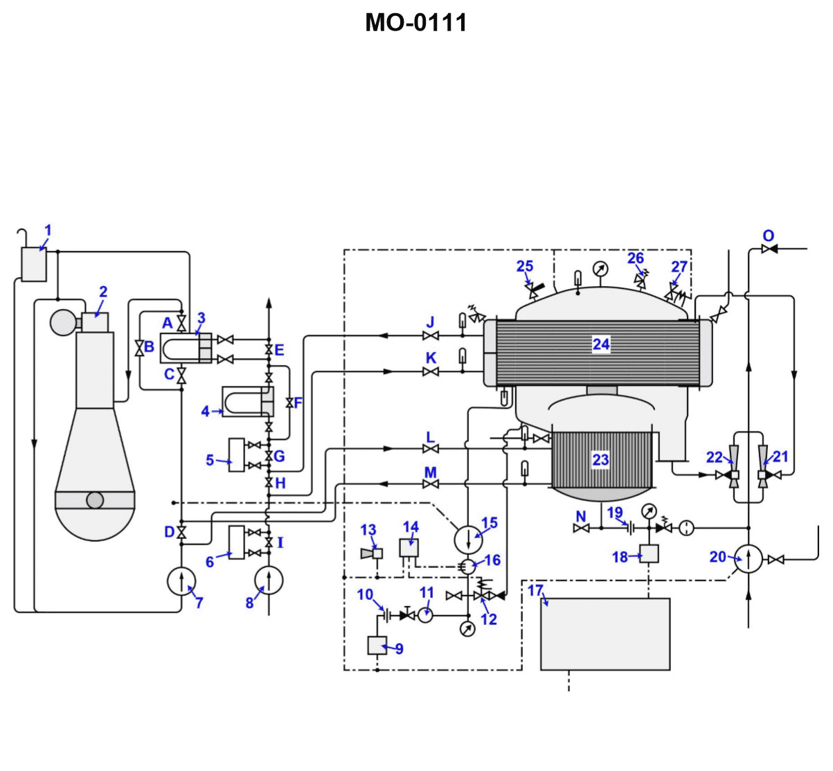
Question 340
Question: Which set of valves will be opened intentionally to remove heat from the main engine jacket cooling water system shown in the illustration? Illustration MO-0111
A. "A" and "C", "L" and "M"
B. "B" and "D", "L" and "M"
C. "G" and "H", "E" and "F"
D. "J" and "K", "G" and "H"
The correct answer is A) "A" and "C", "L" and "M". The main engine jacket cooling water system is designed to remove heat from the engine. To remove heat, the valves "A" and "C" would be opened to allow the flow of cooling water, and the valves "L" and "M" would be opened to allow the heated water to exit the system. This process helps regulate the temperature of the engine and prevent overheating. The other answer choices are incorrect because they do not correctly identify the valves that would be opened to remove heat from the main engine jacket cooling water system.
Question 341
Question: What is the function of the device labeled "3" shown in the illustration? Illustration MO-0111
A. The device specifically serves to remove the latent heat of vaporization from the jacket water.
B. The cooler removes sensible heat from the jacket water.
C. The heat exchanger serves to heat the jacket water during cold water operation.
D. The jacket water cooler is used to raise the temperature of the sea water flowing through it.
The correct answer is B) The cooler removes sensible heat from the jacket water. The jacket water cooler, labeled as "3" in the illustration, functions to remove the excess heat generated by the engine's combustion process from the jacket water. This helps maintain the engine at its optimal operating temperature by dissipating the sensible heat, which is the heat that raises the temperature of the jacket water, rather than the latent heat of vaporization. The other options are incorrect because: A) the device does not specifically remove latent heat of vaporization, C) the jacket water cooler is used to cool the jacket water, not heat it, and D) the purpose is to cool the jacket water, not raise the temperature of the sea water flowing through it.
Question 342
Question: What is the function of the item "7" shown in the illustration? Illustration MO-0111
A. This jacket water pump circulates fresh water throughout the engine cooling and distiller heating systems.
B. This circulating salt water pump will supply feedwater for the operation of the distiller.
C. This jacket water pump supplies the distiller with sea water feed while also powering the eductors.
D. This jacket water pump circulates salt water through the jacket water cooling system to provide engine cooling.
The correct answer is A. This jacket water pump circulates fresh water throughout the engine cooling and distiller heating systems. The pump labeled "7" in the illustration is responsible for circulating the fresh water coolant through the engine and the distiller's heating system, which is a common function of a jacket water pump on marine diesel engines. The other answer choices are incorrect because they describe functions of a different type of pump, such as a circulating salt water pump or an eductor-type pump, which would not be the primary function of the item labeled "7" in this particular illustration.
Question 344
Question: The operation of the lube oil cooler, shown in the illustration as item No.4, will be characterized by which of the following statements? Illustration MO-0111
A. The temperature of the lube oil entering the cooler will decrease whenever the distiller is on line.
B. The temperature of the sea water entering the cooler will be higher when operating with the distiller on line.
C. The pressure of the lube oil to the cooler will increase whenever the distiller is on line.
D. The pressure of the sea water to the lube oil cooler will increase with the distiller on line.
The correct answer is B) The temperature of the sea water entering the cooler will be higher when operating with the distiller on line. When the distiller is in operation, it generates heat to produce freshwater from seawater. This increased temperature of the seawater exiting the distiller will result in a higher temperature of the seawater entering the lube oil cooler, as the cooler utilizes this seawater to remove heat from the lube oil. The other options are incorrect because: A) The temperature of the lube oil entering the cooler would decrease regardless of the distiller being on or off, as that is the purpose of the cooler. C) The pressure of the lube oil to the cooler would not be affected by the distiller operation. D) The pressure of the seawater to the lube oil cooler would also not be affected by the distiller operation.
Question 345
Question: What is the primary function of item '15' shown in the illustration? Illustration MO-0111
A. It is the chemical cleaning pump used in conjunction with valve "12".
B. It removes the vapor condensed in area "23".
C. It removes the distillate condensed in area "24".
D. It is used to empty the evaporator section when there is tube leakage while the unit is secured.
The correct answer is C) It removes the distillate condensed in area "24". The primary function of item '15' shown in the illustration MO-0111 is to remove the distillate condensed in area "24" of the system. This is the correct answer based on the typical operation and components of a distillation system, where the condensed distillate is collected and removed for further processing or storage. The other answer choices are incorrect because: A) the chemical cleaning pump is typically a separate component, not labeled as item '15'; B) removing vapor condensation is generally handled by a different component; and D) emptying the evaporator section is not the primary function of item '15' in this particular illustration.
Question 346
Question: Which of the following statements represents the two major functions provided by the item labeled "20" shown in the illustration? Illustration MO-0111
A. The pump supplies the motive force to the ejectors and removes the excess distillate.
B. The pump is used to drain the shell when the unit is secured, in addition to powering the ejectors.
C. The pump provides for venting of associated equipment while also powering the ejectors.
D. The pump supplies the motive fluid to the ejectors in addition to supplying the feedwater to the distiller.
The correct answer is D. The pump supplies the motive fluid to the ejectors in addition to supplying the feedwater to the distiller. This is correct because the pump labeled "20" in the illustration is responsible for two primary functions - powering the ejectors that remove excess distillate, and supplying the feedwater to the distiller unit. The pump provides the motive force to drive the ejectors as well as delivering the necessary feedwater to the distillation system. The other options are incorrect because they do not fully capture the dual role of the pump in both powering the ejectors and supplying the feedwater, which are the two major functions provided by the item labeled "20" in the illustration.
Question 347
Question: The items labeled "21" and "22", shown in the illustration are used to remove_______________. Illustration MO-0111
A. distillate and non-condensable gases
B. non-condensable gases from two separate sections of the distiller
C. brine and jacket water from the condenser
D. non-condensable gases and brine
The correct answer is D) non-condensable gases and brine. The items labeled "21" and "22" in the illustration MO-0111 are used to remove non-condensable gases and brine from the distiller or evaporator system. Non-condensable gases, such as air and carbon dioxide, can accumulate in the system and reduce the efficiency of the distillation process. The brine, which is the concentrated saltwater left behind after the freshwater has been evaporated, also needs to be removed from the system. The other options are incorrect because they do not accurately describe the function of the items labeled "21" and "22". Option A is incorrect as it refers to the removal of distillate, which is the freshwater produced by the distillation process, rather than the non-condensable gases and brine. Options B and C are also incorrect as they do not fully capture the purpose of these items, which is to remove both non-condensable gases and brine from the system.
Question 348
Question: What occurs within the tubes of the device labeled "23" shown in the illustration? Illustration MO-0111
A. The feedwater flowing through the inside of the tubes is being heated by the jacket water on the outside of the tubes.
B. The heat from the jacket water passing within the tubes is being transferred to the feedwater on the outside of the tubes.
C. The heat of combustion from the engine is being transferred azeotropically, adding latent heat to the entering jacket water.
D. The heat being transferred is subliminal; therefore expansion is taking place within the tubes.
The correct answer is A) The feedwater flowing through the inside of the tubes is being heated by the jacket water on the outside of the tubes. This is the correct answer because the device labeled "23" in the illustration is likely a heat exchanger, where the jacket water from the engine is used to heat the feedwater before it enters the boiler. The heat from the jacket water passing on the outside of the tubes is transferred to the feedwater flowing through the inside of the tubes, increasing the temperature of the feedwater before it enters the boiler. The other answer choices are incorrect because B) describes the opposite heat transfer, C) refers to an azeotropic process which is not relevant here, and D) mentions subliminal heat transfer, which is not a real physical phenomenon.
Question 349
Question: Which of the following statements describes what will occur to the volume of water vapor as it is exposed to the lower temperatures existing in the device labeled "24" shown in the illustration? Illustration MO-0111
A. The volume is increased as condensation occurs at the tube surfaces.
B. The volume will increase if the valve labeled "J" is opened excessively, resulting in an increase of the distiller absolute pressure.
C. The volume is greatly reduced, contributing to condensation within the condenser.
D. The latent heat of condensation is removed causing the volume to increase.
The correct answer is C) The volume is greatly reduced, contributing to condensation within the condenser. The key is that as the water vapor is exposed to the lower temperatures in the device labeled "24", the volume of the water vapor will decrease. This is because the lower temperatures cause the water vapor to condense, resulting in a reduction in the overall volume of the water vapor. The condensation process removes the volume of the water vapor, contributing to the condensation within the condenser. The other options are incorrect because: A) Increasing volume due to condensation is the opposite of what occurs; B) Increasing the distiller pressure would not directly reduce the volume of the water vapor; and D) Removing latent heat of condensation would cause the volume to decrease, not increase.
Question 350
Question: Device "27" shown in the illustration is used to_______________. Illustration MO-0111
A. purge the unit of non-condensable gases
B. add de-scaling chemicals as needed
C. regulate maximum vacuum during normal operation
D. relieve excess pressure
The correct answer is C) regulate maximum vacuum during normal operation. The device "27" shown in the illustration is likely a vacuum regulator, which is used to control and limit the maximum vacuum level in the system. This is an important safety feature to prevent excessive vacuum conditions that could damage equipment or pose a hazard. The other answer choices are incorrect because: A) purging non-condensable gases is typically done by a different mechanism, B) adding descaling chemicals is not the function of this particular device, and D) relieving excess pressure is typically done by a pressure relief valve, not the vacuum regulator.
Question 351
Question: Which of the valve arrangements listed would be correct for operating the distillation plant shown in the illustration? Illustration MO-0111
A. Valves "C", "J", "K", "L", "M" open, valves "A", "B", "D", and "H" closed.
B. Valves "D", "H", "J", "K", "L", "M" open, valves "I", "G", "F", and "E" closed.
C. Valves "H", "J", "K", "L", "M" open, valve "D" closed.
D. Valves "J", "K", "L", "M" open, valves "D" and "H" closed.
The correct answer is D) Valves "J", "K", "L", "M" open, valves "D" and "H" closed. This is the correct answer because the illustration MO-0111 shows the distillation plant in operation, and the correct valve arrangement for this operation is to have valves "J", "K", "L", and "M" open to allow the flow of distilled water, while valves "D" and "H" should be closed to prevent the ingress of untreated water or the escape of distilled water. The other options are incorrect because they either have the wrong combination of open and closed valves, or they include valves that should be in the opposite state for the distillation plant to function properly.
Question 352
Question: Excess brine accumulated in the distiller, shown in the illustration, is removed during normal operation by_______________. Illustration MO-0111
A. opening the drain valve located to the left of orifice "19"
B. orifice "19" regulating the amount of feedwater entering the distiller, thereby preventing excess brine accumulation
C. the hydrokineter labeled "21"
D. the continuous action of ejector "22"
The correct answer is D) the continuous action of ejector "22". The illustration shows a distiller system, and in normal operation, excess brine is continuously removed by the action of the ejector labeled "22". The ejector uses the principle of the Venturi effect to create suction and draw the excess brine out of the distiller, preventing it from accumulating. This is the intended method for removing excess brine during regular operation. The other options are incorrect because: A) opening a drain valve is not the normal method for removing excess brine, B) orifice "19" regulates feedwater, not brine removal, and C) the hydrokineter labeled "21" is for measuring the density of the brine, not removing it.
Question 353
Question: During operation which device listed removes air and non-condensable gases from the unit shown in the illustration? Illustration MO-0111
A. "21"
B. "22"
C. "25"
D. "27"
The correct answer is A) "21". The device labeled "21" in the illustration MO-0111 removes air and non-condensable gases from the unit. This is typically an air vent or air release valve, which serves to eliminate air pockets and prevent air from building up in the system. This is an essential function to maintain the proper operation and efficiency of the equipment. The other answer choices are incorrect because they do not represent the component responsible for removing air and non-condensable gases from the unit. Devices labeled "22", "25", and "27" likely serve other functions, such as regulating pressure, controlling flow, or providing access for maintenance, but they do not specifically remove air and non-condensable gases.
Question 354
Question: The graphic dotted line between items "27", "12", "9", and "20", shown in the illustration, is used to indicate the use of_______________. Illustration MO-0111
A. electrical conduits and circuitry
B. thermal venting devices
C. ambient venting devices
D. single wire controls
The correct answer is A) electrical conduits and circuitry. The dotted line in the illustration indicates the routing of electrical conduits and circuitry between the labeled components. Electrical conduits are used to enclose and protect electrical wiring, ensuring safe and reliable power distribution throughout the system. The use of conduits is a standard practice in maritime and industrial applications to meet safety regulations and prevent damage to the electrical system. The other answer choices, such as thermal venting devices, ambient venting devices, and single wire controls, are not directly related to the purpose of the dotted line in the illustration, which is specifically indicating the path of electrical conduits and circuitry.
Question 355
Question: Excluding line losses, how many distinct pressure drops will occur as sea water flows through all the heat exchangers in the cooling system shown in the illustration? Illustration MO-0111
A. 3
B. 4
C. 5
D. 6
The correct answer is C) 5 distinct pressure drops. As sea water flows through the cooling system, it will experience pressure drops across each of the heat exchangers. Excluding line losses, there will be 5 distinct pressure drops: one each across the main engine heat exchanger, the lube oil cooler, the fuel oil cooler, the air compressor cooler, and the generator cooler. The other answer choices are incorrect because 3 pressure drops is too few, 4 pressure drops is missing one of the coolers, and 6 pressure drops would include additional unnecessary pressure drops.
Question 356
Question: Which device is used to prevent overpressurization of the illustrated distiller? Illustration MO-0111
A. "12"
B. "13"
C. "19"
D. "26"
The correct answer is D) "26". The device used to prevent overpressurization of the illustrated distiller is a pressure relief valve, which is typically labeled as item "26" in distiller system diagrams. This pressure relief valve is a safety mechanism that opens to release excess pressure and prevent the distiller from becoming overpressurized, which could lead to a dangerous situation. The other answer choices, such as "12", "13", and "19", represent different components of the distiller system, but they do not specifically function to prevent overpressurization.
Question 357
Question: Where is the latent heat obtained to create vapor from the feedwater in the illustrated distiller? Illustration MO-0111
A. During its contact period with heat exchanger "3".
B. Only as it passes through device "20".
C. From having passed through "23".
D. While it is in contact with device "24".
The correct answer is C) From having passed through "23". The latent heat required to create vapor from the feedwater in the illustrated distiller is obtained as the feedwater passes through device "23", which is likely a preheater or heat exchanger. As the feedwater passes through this component, it absorbs heat, which provides the necessary latent heat to transform the liquid water into vapor. This is a common process in distillation systems, where the feedwater is preheated before entering the main distillation chamber to improve efficiency and reduce energy consumption. The other options are incorrect because: A) The contact period with heat exchanger "3" does not directly generate the latent heat for vaporization; B) Device "20" is likely not the sole source of the latent heat; and D) Device "24" is likely the distillation chamber, where the vaporization occurs, rather than the source of the latent heat.
Question 358
Question: Which of the following statements describes the approximate relation between the feedwater entering the unit shown in the illustration and brine being removed? Illustration MO-0111
A. Seventy-five percent of the feedwater entering the unit is removed as brine.
B. The brine will be removed at a faster rate than feedwater entering to prevent the possibility of flooding.
C. Twenty-five percent of the feedwater entering the device is removed as brine.
D. The amount of feedwater entering the distiller is dependent upon the condition of device "7", while the amount of brine leaving is dependent upon the condition of device "21".
The correct answer is A) Seventy-five percent of the feedwater entering the unit is removed as brine. This is the correct answer because in a typical desalination process, around 75% of the feedwater entering the unit is removed as brine concentrate, while the remaining 25% is produced as freshwater. This ratio is a common design parameter for desalination systems, as it allows for efficient removal of salts and minerals while maximizing freshwater production. The other options are incorrect because B) suggests the brine removal rate would be faster than feedwater entry, which is not typical; C) states the brine removal is 25%, which is lower than the actual 75% ratio; and D) introduces irrelevant variables that do not directly describe the relationship between feedwater and brine removal.
Question 359
Question: Item "10" shown in the illustration is used to_______________. Illustration MO-0111
A. regulate flow from the drain pump
B. prevent damage to device "9" by reducing turbulence
C. direct the flow from the distillate pump
D. cancel the effects of improper regulation developed by device "11"
The correct answer is C) direct the flow from the distillate pump. In the context of a US Coast Guard Captain's License Examination, item "10" shown in the illustration MO-0111 is likely a valve or piping component used to control and direct the flow of distillate (purified water) from the distillate pump. This is a critical function to ensure the proper operation and distribution of the distillate within the system. The other answer choices are incorrect because: A) regulating the flow from the drain pump is not the primary function of item "10"; B) reducing turbulence is not the main purpose of this component; and D) item "10" does not directly cancel the effects of improper regulation by device "11".
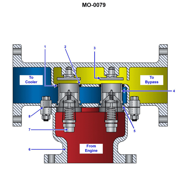
Question 363
Question: The thermostatic valve in the illustration is used for controlling the coolant temperature in a main propulsion diesel engine. Which of the following can be used to verify proper valve operation with the valve disassembled? Illustration MO-0079
A. Check spring compression values against data given in manufacturer's handbook.
B. Chemically analyze contents of power pellet.
C. Remove and examine the contents of the power pellet.
D. Place the thermostatic element in a container of water at various operating temperatures and note the movement of the valve stem.
The correct answer is D) Place the thermostatic element in a container of water at various operating temperatures and note the movement of the valve stem. This is the correct answer because the proper way to verify the operation of a thermostatic valve is to test the thermostatic element directly by exposing it to different temperatures and observing how the valve stem moves in response. This allows you to directly evaluate the functionality of the key component that controls the valve's operation. The other options are incorrect because A) checking spring compression values would not test the thermostatic element itself, B) analyzing the power pellet chemically would not directly evaluate valve operation, and C) removing and examining the power pellet would also not test the thermostatic element's function.
Question 379
Question: The diesel engine shown in the illustration, is provided with an auxiliary blower to_______________. Illustration MO-0003
A. provide scavenge air pressure at low load
B. maintain a positive pressure on the crankcase
C. increase scavenge air pressure at full load
D. maintain a vacuum on the crankcase
The correct answer is A) provide scavenge air pressure at low load. The auxiliary blower in the diesel engine illustration is used to provide additional air pressure to the engine's scavenge air system, particularly at low engine loads. This helps ensure sufficient air flow through the engine cylinders, which is crucial for complete combustion and efficient operation, especially when the engine is not generating enough natural air flow on its own at low loads. The other answer choices are incorrect because: B) maintaining a positive pressure on the crankcase is not the primary function of the auxiliary blower, C) increasing scavenge air pressure at full load is not necessary as the engine's natural air flow is sufficient at high loads, and D) maintaining a vacuum on the crankcase is not the role of the auxiliary blower.
Question 383
Question: Air scavenging of the cylinder shown in the illustration begins between figures_______________. Illustration MO-0025
A. 2 and 3
B. 3 and 4
C. 4 and 5
D. 5 and 6
The correct answer is B) 3 and 4. The air scavenging of the cylinder shown in the illustration begins between figures 3 and 4. This is because the piston is moving downwards in figure 3, drawing in a fresh air charge, and then in figure 4 the piston is moving upwards, expelling the exhaust gases and allowing fresh air to enter the cylinder. The other answer choices are incorrect because: A) Air scavenging does not begin between figures 2 and 3, as the piston is still moving downwards in figure 2. C) Air scavenging does not begin between figures 4 and 5, as the piston is already in the upward stroke in figure 4. D) Air scavenging does not begin between figures 5 and 6, as the piston is already in the downward stroke in figure 5.
Question 390
Question: Regarding the turbocharger shown in the illustration, the part labeled "B" would be attached to the_______________. Illustration MO-0080
A. nozzle ring
B. silencer outlet
C. exhaust manifold
D. aftercooler inlet
The correct answer is D) aftercooler inlet. The part labeled "B" in the illustration MO-0080 would be attached to the aftercooler inlet. The aftercooler is a critical component of the turbocharger system, as it helps to cool the compressed air coming from the turbocharger before it enters the engine. This cooling process increases the density of the air, which improves the engine's efficiency and power output. The other answer choices are incorrect because they do not accurately represent the component that part "B" would be connected to. The nozzle ring, silencer outlet, and exhaust manifold are not the correct locations for this particular part within the turbocharger system.
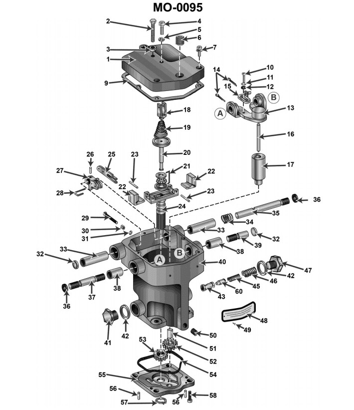
Question 394
Question: If governor Item No.19 in the illustration were to break on a diesel engine operating under full load, the engine RPM will_______________. Illustration MO-0095
A. increase until the overspeed trip actuated
B. hunt until stabilized by droop rod
C. decrease to a slightly lower value
D. remain the same until manually changed
The correct answer is C) decrease to a slightly lower value. If governor Item No.19 in the illustration were to break on a diesel engine operating under full load, the engine RPM would decrease to a slightly lower value. This is because the governor is responsible for maintaining the engine RPM at the desired setpoint. When the governor fails, the engine is no longer able to maintain the full load RPM, and the RPM will drop slightly to a new, lower equilibrium value. The other answer choices are incorrect. The engine RPM would not increase until the overspeed trip actuated (A), as the governor failure would cause a decrease in RPM, not an increase. The engine would not "hunt until stabilized by droop rod" (B), as the droop rod is part of the governor system that has failed. The RPM would not remain the same until manually changed (D), as the governor failure would immediately cause the RPM to decrease.
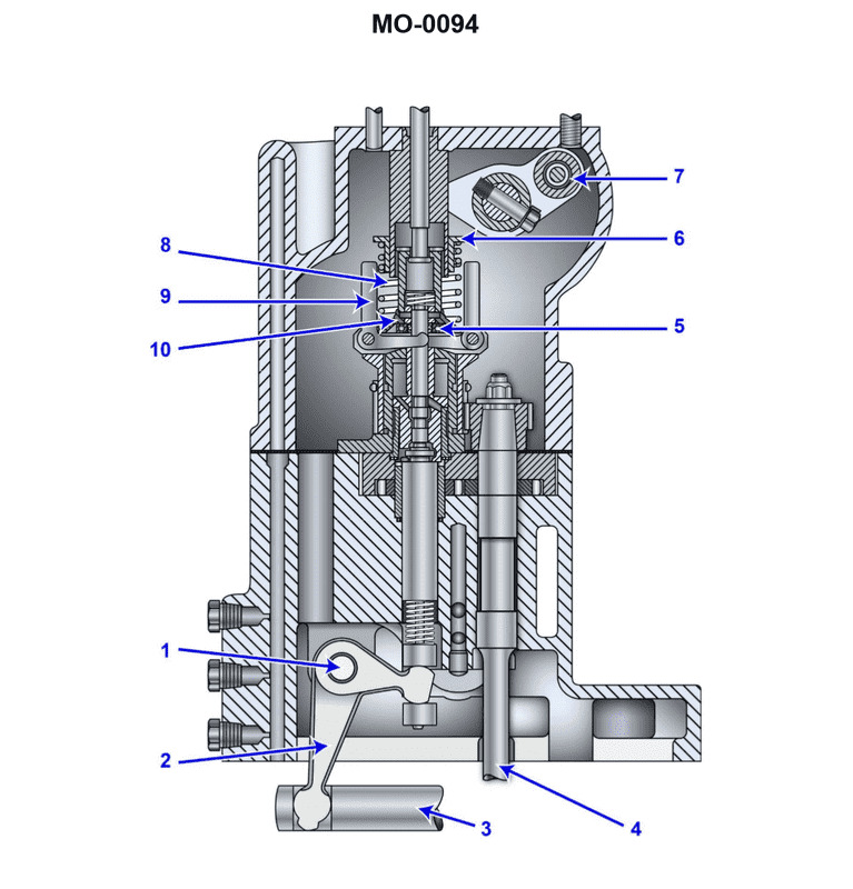
Question 395
Question: In the illustrated auxiliary diesel engine governor, decreasing the distance between piece No.6 and piece No.10 will affect the engine by_______________. Illustration MO-0094
A. decreasing the speed
B. increasing the speed
C. increasing the speed droop setting
D. decreasing the overspeed trip setting
The correct answer is B) increasing the speed. In the illustrated auxiliary diesel engine governor, decreasing the distance between piece No. 6 and piece No. 10 will increase the speed of the engine. This is because piece No. 6 is the speed setting device, and reducing the distance between it and piece No. 10, which is the spring, will increase the tension on the spring. This increased spring tension will cause the governor to apply less force to the fuel system, allowing the engine to run at a higher speed. The other answer choices are incorrect because: A) Decreasing the distance would increase the speed, not decrease it. C) Increasing the speed droop setting is not the same as increasing the speed. D) Decreasing the overspeed trip setting is not related to the change in distance between the pieces.
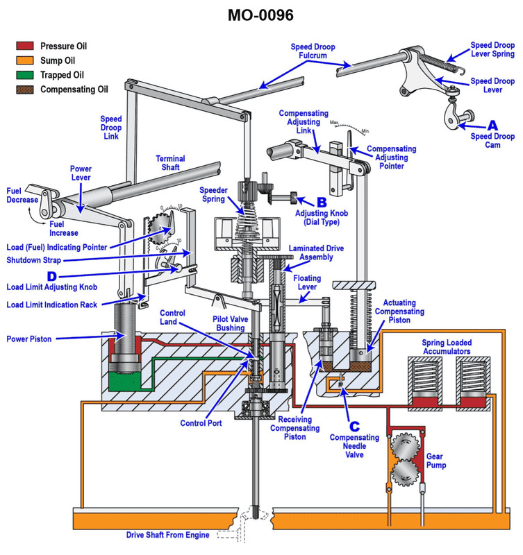
Question 396
Question: Which of the following statements is correct concerning the operating function of the governor shown in the illustration? Illustration MO-0096
A. The dial type adjusting knob
B. is used for setting speed droop and damping out hunting.
C. Excess oil under high-pressure is released from the spring loaded accumulators to the sump.
D. The speed droop lever spring prevents the engine from racing or hunting by arresting the movement of the power piston after a speed change.
The correct answer is D) The speed droop lever spring prevents the engine from racing or hunting by arresting the movement of the power piston after a speed change. This is correct because the governor's primary function is to maintain a constant engine speed by adjusting the fuel supply in response to load changes. The speed droop lever spring helps dampen speed fluctuations and prevent the engine from overshooting the desired speed, which could lead to engine damage or instability. The other options are incorrect - option A refers to a different component, option B describes a different function of the governor, and option C does not accurately describe the role of the accumulators in the governor system.
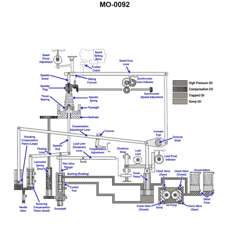
Question 405
Question: As the load is being decreased on the engine controlled by the governor shown in the illustration, the_______________. Illustration MO-0092
A. right hand end of the floating lever will move up
B. speeder rod will move down
C. pilot valve plunger will move down
D. oil pressure under the power piston will increase
The correct answer is A) the right-hand end of the floating lever will move up. As the load on the engine is decreased, the engine speed will increase. This causes the right-hand end of the floating lever to move upwards, which in turn causes the speeder rod to move downwards. This downward movement of the speeder rod reduces the amount of fuel delivered to the engine, bringing the engine speed back to the desired setting. The other answer choices are incorrect because: B) the speeder rod will move down (as explained above), C) the pilot valve plunger will not move down, and D) the oil pressure under the power piston will decrease, not increase, as the load on the engine is reduced.
Question 406
Question: The function of the synchronizing motor on the generator governor illustrated is to_______________. Illustration MO-0092
A. drive the terminal shaft at a set speed
B. turn the governor drive shaft during start-up
C. provide remote control for speed adjustment
D. power the generator synchronizing lamps
The correct answer is C) provide remote control for speed adjustment. The synchronizing motor on the generator governor is responsible for remotely controlling the speed adjustment of the generator. This allows the generator's speed to be adjusted from a remote location, which is important for synchronizing the generator with the power grid. The synchronizing motor does not directly drive the terminal shaft (A), turn the governor drive shaft during start-up (B), or power the generator synchronizing lamps (D). These other options are incorrect as they do not accurately describe the primary function of the synchronizing motor in the generator governor system.
Question 407
Question: The governor, shown in the illustration, will have its preset speed droop altered whenever_______________. Illustration MO-0092
A. the compensating lever fulcrum is changed
B. the speed droop lever fulcrum is changed
C. the speeder spring tension is changed
D. all of the above
The correct answer is B) the speed droop lever fulcrum is changed. The speed droop of a governor is the reduction in speed that occurs as the load on the engine increases. The speed droop lever fulcrum determines the amount of speed droop, so changing the position of this fulcrum will alter the preset speed droop of the governor. The other options are incorrect because changing the compensating lever fulcrum or the speeder spring tension would not directly affect the preset speed droop - these adjustments would impact other governor characteristics rather than the speed droop specifically.
Question 416
Question: When installing the bearing cap on the device shown in the illustration, which of the precautions listed must be observed? Illustration MO-0121
A. Once the bearing cap is properly torqued, measure the end gap dimensions to ascertain even tightening of the cap.
B. If the device is covered with abrasive material or contaminates, the unit may be reassembled, provided an abnormal method of reassembly is followed.
C. Prior to installing the cap, position the thrust shoes in their proper locations.
D. After applying anti-seize to the external threads, torque one side at a time to the appropriate values using a quality torque wrench.
The correct answer is A) Once the bearing cap is properly torqued, measure the end gap dimensions to ascertain even tightening of the cap. This is the correct answer because it is important to ensure the bearing cap is tightened evenly to prevent damage to the bearing or other components. Measuring the end gap dimensions after torqueing the cap allows the technician to verify the cap has been tightened properly and evenly. The other options are incorrect because: B) Reassembling a device with contaminants is generally not recommended, as it can lead to premature failure; C) Positioning the thrust shoes in the proper locations is important, but it does not directly relate to installing the bearing cap; and D) Torqueing one side at a time is not necessary for a bearing cap installation.
Question 417
Question: What is the normal bearing clearance permitted at the horizontal axis of the shaft for the bearing shown in the illustration? Illustration MO-0121
A. The clearance is determined by the thickness of the hydrodynamic wedge formed and is not usually measured while underway.
B. The tolerances established are dependent on machining processes used and will vary amongst manufacturers.
C. The normal play on both sides of the shaft will be one tenth of a millimeter.
D. The clearance on one side of the shaft at the axis will be one twentieth of a millimeter.
The correct answer is C) The normal play on both sides of the shaft will be one tenth of a millimeter. This is the correct answer because the typical bearing clearance for a marine shaft bearing is around 0.1 mm (one tenth of a millimeter) on each side of the shaft, which allows for proper lubrication and movement of the shaft within the bearing. This clearance is a standard specification that is commonly used in the design and manufacture of marine propulsion systems. The other answer choices are incorrect because: A) The clearance is not determined by the hydrodynamic wedge, but rather by engineering specifications. B) The tolerances are standardized and do not vary significantly between manufacturers. D) The clearance of one twentieth of a millimeter (0.05 mm) is too small and not the normal specification for this type of bearing.
Question 418
Question: After following the prescribed procedures to measure the thrust bearing clearance shown in the illustration, the distance "F" is determined to be 200 mm, and 'f1' is 2.3 mm. Which of the following statements describes the condition indicated by these dimensions? Illustration MO-0121
A. These dimensions indicate the presence of flourishing marks on the thrust shoes; the marks becoming visible as the distance at 'f1' increases.
B. It is possible for the shaft to move axially 2.3 mm during astern operation and relates to an excess movement of 1.3 mm, 0.3 mm beyond the maximum worn play.
C. The loading ratio, or shaft diameter divided by collar surface area is within 2.7:1.
D. The total active thrust area is 202.3 mm, well within the standards set forth by the GSMA (German Society for Machining Accuracy).
The correct answer is B. These dimensions indicate that the shaft is able to move axially 2.3 mm during astern operation, which is 1.3 mm more than the maximum worn play typically allowed. This excess axial movement of the shaft suggests potential issues with the thrust bearing clearance and requires further inspection or adjustment to bring it within the recommended specifications. The other answer choices are incorrect because: A) Flourishing marks on the thrust shoes are not directly indicated by the given dimensions. C) The loading ratio is not provided, so this statement cannot be verified. D) The total active thrust area of 202.3 mm does not necessarily fall within any specific standards without more context.
Question 425
Question: When tightening the lock ring "G" of the device shown in the illustration, two events are simultaneously accomplished. Which of the following statements represents these events? Illustration MO-0112
A. The lock ring insures proper contact between the bowl top and the sliding bowl bottom, in addition to compressing the disc stack.
B. The lock ring forces the disc stack onto the spindle, providing a positive means of rotation and locating the bowl top to seal the separation chamber.
C. When tightened, the lock ring allows for movement of the sliding piston and positions the sliding piston within the bowl bottom.
D. The lock ring insures proper positioning of the disc stack and maintains a positive contact of the bowl top and bowl bottom.
The correct answer is C. When tightening the lock ring "G" of the device shown in the illustration, it allows for movement of the sliding piston and positions the sliding piston within the bowl bottom. This is correct because the lock ring is responsible for securing the sliding piston or bowl bottom in place, enabling the proper operation of the device. Tightening the lock ring ensures the sliding piston can move freely within the bowl bottom, which is a critical function for the device to work as intended. The other answer choices are incorrect because they do not accurately represent the specific events that occur when tightening the lock ring. The lock ring does not directly ensure contact between the bowl top and bottom, compress the disc stack, or maintain the positioning of the disc stack, as described in the other options.
Question 426
Question: After removing the bowl hood of the device shown in the illustration, excessive quantities of sludge are visible. Which of the following statements represents the approach to rectify the situation? Illustration MO-0112
A. Disassemble the entire unit, clean all components, replace all defective discs and use the proper lubricant where required.
B. Steam clean the components in place, check for proper alignment, using the match marks provided, reassemble and restart the unit.
C. Remove only the disc stack, separate all the discs, clean with steel wool and solvent, replace the disc stack ensuring it is located by use of the dowel pin shown.
D. Disassemble the entire unit, clean all components, replace any defective gaskets and use the proper lubricants where required.
The correct answer is D) Disassemble the entire unit, clean all components, replace any defective gaskets and use the proper lubricants where required. This is the correct approach because excessive sludge buildup in a device typically indicates that the entire unit needs to be disassembled, cleaned, and serviced. Merely steam cleaning or partially disassembling the components may not address the root cause of the sludge buildup. Thoroughly cleaning all parts, replacing any worn or defective gaskets, and using the proper lubricants is the best way to rectify the situation and restore the device to proper working order. The other options are incorrect because they either do not involve a complete disassembly and cleaning (B and C) or they do not mention replacing defective gaskets and using the proper lubricants (A).
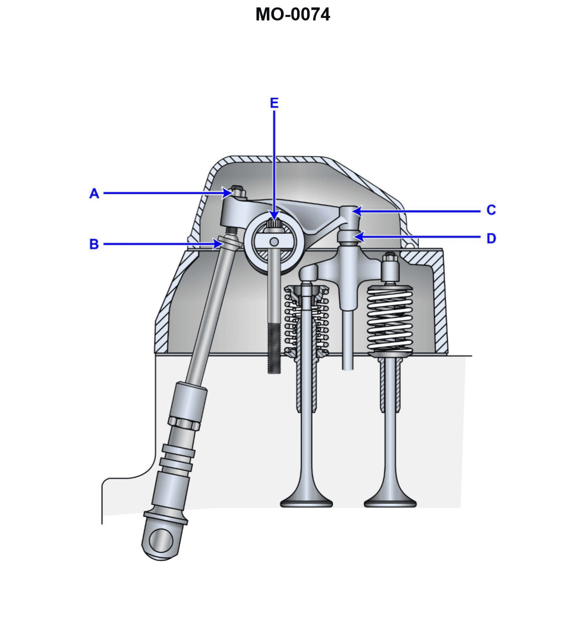
Question 432
Question: When inspecting the valve mechanism shown in the illustration, normal maintenance would include_______________. Illustration MO-0074
A. mechanically adjusting the valve at point "D"
B. mechanically adjusting the valve at point "E"
C. changing the tappet clearance as measured between points "A" and "B"
D. measuring the cold valve clearance between components "C" and "D"
The correct answer is D) measuring the cold valve clearance between components "C" and "D". The valve clearance, which is the gap between the valve stem and the rocker arm, needs to be checked and adjusted as part of normal maintenance on the valve mechanism. Measuring the cold valve clearance between components "C" and "D" is the appropriate procedure, as this ensures the valve is opening and closing properly. The other options, such as adjusting the valve at points "D" or "E", or changing the tappet clearance, are not the correct maintenance steps for this particular valve mechanism.
Question 434
Question: Which of the following statements would apply when checking the valve clearance of the unit shown in the illustration? Illustration MO-0074
A. Tappet clearance is measured between points "A" and "B".
B. Cold valve clearance is measured between components "C" and "D".
C. The valve is mechanically adjusted at point "D".
D. The valve is mechanically adjusted at point "E".
The correct answer is B) Cold valve clearance is measured between components "C" and "D". This is correct because the valve clearance is typically measured between the valve stem and the rocker arm or tappet, which correspond to components "C" and "D" in the illustration. The valve clearance is checked when the engine is cold to ensure proper adjustment and to prevent damage to the valve train components during operation. The other options are incorrect because A) refers to the tappet clearance, which is not the same as the valve clearance, C) and D) refer to the adjustment points, not the measurement locations.
Question 445
Question: Which of the following statements describes what will occur if the annular spaces, indicated by the letter "K" of the device shown in the illustration, became restricted? Illustration MO-0112
A. The bowl will fail to close, but the unit will be capable of shooting while in operation.
B. Operating water will be supplied through port "S".
C. The unit will not start due to pressure/time delay relays.
D. The bowl will fail to close when starting and the unit will not shoot when operating.
The correct answer is D) The bowl will fail to close when starting and the unit will not shoot when operating. This is correct because if the annular spaces (indicated by the letter "K") become restricted, it will prevent the proper operation of the device. Specifically, the restricted annular spaces will prevent the bowl from closing properly, which is necessary for the unit to start and operate. Without the bowl closing, the unit will not be able to shoot when in operation. The other options are incorrect because they do not accurately describe the consequences of the annular spaces becoming restricted. Option A is incorrect because the bowl failing to close would prevent the unit from operating at all. Option B is incorrect because the restricted annular spaces would not cause water to be supplied through a different port. Option C is incorrect because the restricted annular spaces would not trigger pressure/time delay relays, but rather prevent the proper functioning of the device.
Question 446
Question: As shown in the illustration, which of the following conditions would be responsible for a "low-pressure in oil outlet" alarm to be indicated? Illustration MO-0127
A. Throughput too low
B. Separating temperature too low
C. Controller setpoint changed
D. Emergency stop button not reset
The correct answer is A) Throughput too low. A low-pressure alarm in the oil outlet would indicate that the oil flow or throughput is too low. This could be caused by a blockage or restriction in the oil line, a malfunctioning pump, or other issues that reduce the oil flow. Separating temperature, controller setpoint, and the emergency stop button are not directly related to causing a low-pressure alarm in the oil outlet. The other answer choices are incorrect because they do not directly impact the oil outlet pressure. A low separating temperature, changed controller setpoint, or an un-reset emergency stop button would not independently trigger a low-pressure alarm in the oil outlet.
Question 447
Question: While operating the fuel oil centrifuge shown in the illustration, the bowl fails to open for sludge ejection. The probable cause is that_______________. Illustration MO-0012
A. one or more of the sludge ports is partially clogged
B. the operating water pressure is too high
C. the bowl disk set is clogged
D. the seal ring on the operating slide is defective
The correct answer is D) the seal ring on the operating slide is defective. The seal ring on the operating slide is responsible for maintaining the proper pressure within the centrifuge bowl during operation. If this seal ring is defective, it can cause a loss of pressure, preventing the bowl from opening properly for sludge ejection. This is the most likely cause of the issue described in the question. The other answer choices are incorrect because they do not directly address the issue with the seal ring. Clogged sludge ports (A) or a clogged bowl disk set (C) would not necessarily prevent the bowl from opening, and high operating water pressure (B) is not the primary cause of the problem described.
Question 448
Question: While operating the fuel oil centrifuge shown in the illustration, the fuel oil is being continuously ejected with the sludge and the seal water. The probable cause is the _______________. Illustration MO-0012
A. gravity disk inside diameter is too large
B. gravity disk inside diameter is too small
C. back pressure is too low
D. incorrect number of disks have been placed in the disk stack
A) gravity disk inside diameter is too large is the correct answer. The gravity disk inside the centrifuge is responsible for separating the fuel oil from the sludge and water. If the gravity disk's inside diameter is too large, it will not create enough centrifugal force to effectively separate the fuel oil, causing it to be continuously ejected with the sludge and seal water. The other options are incorrect because: B) a too small gravity disk diameter would have the opposite effect, creating excessive centrifugal force; C) low back pressure would not directly cause the fuel oil to be ejected with the sludge; and D) the number of disks in the stack would not affect the separation caused by the gravity disk's diameter.
Question 451
Question: The thrust bearing shown in the illustration has over eight years of ahead running time. Measurements show "i1" is 4 mm and "i2" is 1 mm. Which of the following conditions is indicated and what steps should be taken, if any? Illustration MO-0121
A. No appreciable wear has occurred, and the proper maintenance procedures should continue to be followed.
B. A wear rate of 1.6 mm per year occurred. Although not excessive, this condition may require more frequent monitoring.
C. The stops in which the thrust bearing block rides are worn, and it is necessary to return these to their original specifications.
D. A wear rate of 1.6 mm per year is excessive and requires immediate assistance from the manufacturer’s field support.
The correct answer is A) No appreciable wear has occurred, and the proper maintenance procedures should continue to be followed. The reasoning is that the measured "i1" of 4 mm and "i2" of 1 mm indicate the thrust bearing has only 3 mm of wear over the 8 years of operation, which is a very low wear rate. This suggests the thrust bearing is still within its normal operating parameters and does not require any special attention beyond the proper maintenance procedures. The other options are incorrect because they indicate excessive wear or issues that are not supported by the provided information.
Question 458
Question: A propulsion engine, using the speed control circuit shown in the illustration, fails to function at speeds lower than the low end of the critical speed range. Which of the following statements describes what should be done to correct this malfunction? Illustration MO-0114
A. Device 17A needs to be replaced, repaired, or reset to the setpoint coinciding with the RPM value for the low end of the critical speed range.
B. The critical speed range will be varied as the setpoints of 17A or 17B are reset, therefore, another segment of the speed control circuit must be repaired.
C. To increase the critical speed range of the engine, reduce the setpoint of 17A and 17B respectively, to 0.80 bar and 1.0 bar.
D. Both 17A and 17B need to be reset to decrease the critical speed range, although this procedure will increase the operating range of the engine.
The correct answer is A) Device 17A needs to be replaced, repaired, or reset to the setpoint coinciding with the RPM value for the low end of the critical speed range. This is the correct answer because if the propulsion engine fails to function at speeds lower than the low end of the critical speed range, it indicates an issue with the speed control circuit, specifically with device 17A. Device 17A is likely malfunctioning or not set to the proper RPM value for the low end of the critical speed range, which is preventing the engine from operating at those lower speeds. Resetting or repairing 17A should correct the issue and restore the engine's functionality within the critical speed range. The other options are incorrect because they either suggest adjusting the wrong components (options B and D) or do not address the root cause of the problem (option C).
Question 459
Question: What would be the first indication that a tube leak has occurred in area '23'? Illustration MO-0111
A. The level in area '1' would decrease.
B. The level in area '1' would increase.
C. The level in area '3' would decrease.
D. The level in area '3' would increase.
The correct answer is A) The level in area '1' would decrease. If there is a tube leak in area '23', this would cause the fluid level in that area to decrease. Since area '1' is connected to area '23' through internal piping, the drop in level in area '23' would result in a corresponding decrease in the level of area '1'. This is because the fluid would be lost from the overall system through the tube leak in area '23'. The other options are incorrect because a tube leak in area '23' would not directly impact the levels in areas '3' or cause the level in area '1' to increase. The key is that the tube leak would result in a fluid loss, leading to a decrease in the level of the connected area '1'.
Question 460
Question: If the wearing rings of device '7' shown in the illustration become worn, how will the evaporation rate in '23' be affected? Illustration MO-0111
A. The rate of evaporation will decrease.
B. The rate of evaporation is dependent on the level of vacuum maintained within the unit, and not the flow of water to the unit.
C. Device '7' does not use wearing rings, as these are normally positive displacement pumps.
D. The rate of evaporation will not be affected as the standby pump; labeled '8' will be used instead.
The correct answer is A) The rate of evaporation will decrease. The wearing of the rings in device '7' will affect the flow of water to the evaporation unit labeled '23'. As the rings wear, the pump's efficiency will decrease, reducing the amount of water flowing to the evaporation unit. This decreased water flow will directly impact the evaporation rate, causing it to decrease. The other answer choices are incorrect: B) The evaporation rate is dependent on the water flow, not just the vacuum level. C) Device '7' is likely a centrifugal or other type of pump that does use wearing rings. D) The standby pump '8' would not be used unless the primary pump '7' failed completely.
Question 461
Question: Which of the conditions listed would indicate a large condenser tube leak within the distiller shown in the illustration? Illustration MO-0111
A. The activation of the salinity monitoring equipment's annunciator circuit.
B. A decrease in the level of the main engine expansion tank as indicated by a low level alarm.
C. An increase in distiller output resulting from the combination of jacket water and the distillate produced.
D. A slow continuous rise in the lube oil cooler outlet temperature indicated at device "4".
The correct answer is A) The activation of the salinity monitoring equipment's annunciator circuit. A large condenser tube leak within the distiller would allow seawater to mix with the distillate, increasing the salinity of the distillate. This would trigger the activation of the salinity monitoring equipment's annunciator circuit, which is designed to detect and alert the operator to such a leak. The other options are incorrect because: B) A decrease in the main engine expansion tank level is not directly related to a condenser tube leak in the distiller. C) An increase in distiller output is not a reliable indicator of a condenser tube leak. D) A rise in the lube oil cooler outlet temperature is not caused by a condenser tube leak in the distiller.
Question 462
Question: If valve "D" is opened during the normal operation of the distiller shown in the illustration, which of the events listed will occur? Illustration MO-0111
A. The jacket water cooler will be overloaded, eventually causing a critical engine alarm.
B. The amount of vapor formed in the evaporator will increase.
C. The output of pump "7" will increase with a corresponding increase in pressure.
D. The amount of vapor being formed in the evaporator will decrease.
The correct answer is D) The amount of vapor being formed in the evaporator will decrease. Opening valve "D" during normal operation of the distiller would allow some of the vapor being formed in the evaporator to escape, rather than being directed through the system. This would reduce the overall amount of vapor being generated, as the evaporator's capacity to produce vapor would be compromised. The other answer options are incorrect because: A) Opening valve "D" would not overload the jacket water cooler or cause an engine alarm. B) Opening valve "D" would decrease, not increase, the amount of vapor formed in the evaporator. C) Opening valve "D" would not increase the output or pressure of pump "7".
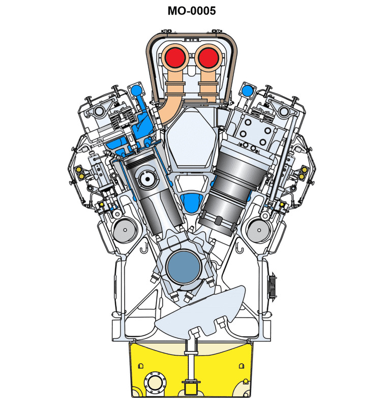
Question 488
Question: The diesel engine shown in the illustration can be fitted with a pyrometer at each exhaust elbow. If one of the cylinder pyrometers is reading significantly higher than the others, which of the following should be your FIRST action? Illustration MO-0005
A. Check the pump rack setting.
B. Examine the water outlet header for evidence of blockage.
C. Replace the fuel injector nozzle.
D. Examine the exhaust valves for evidence of burning.
The correct answer is A) Check the pump rack setting. If one cylinder's pyrometer is reading significantly higher than the others, this indicates an issue with that cylinder's fuel delivery. The first step should be to check the pump rack setting, as this controls the amount of fuel injected into each cylinder. An issue with the pump rack setting could be causing uneven fuel distribution, leading to the observed temperature discrepancy. The other options are not the correct first step. Checking for exhaust blockage (B), replacing the fuel injector nozzle (C), or examining the exhaust valves (D) are all potential troubleshooting steps, but they should not be the immediate first action. Checking the pump rack setting is the most logical and direct way to address the issue indicated by the uneven pyrometer readings.
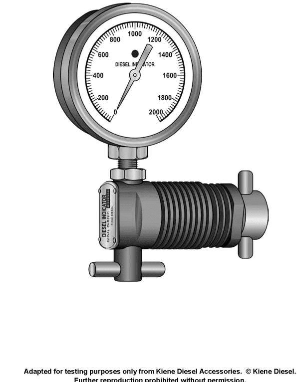
Question 489
Question: The instrument shown in the illustration would be used on a diesel engine to_______________. Illustration MO-0031
A. measure cylinder compression or firing pressures
B. balance exhaust gas temperature readings
C. measure exhaust gas pressure
D. measure concentration of chromate in jacket water
The correct answer is A) measure cylinder compression or firing pressures. The instrument shown in the illustration MO-0031 is a compression gauge, which is used to measure the compression or firing pressures within the cylinders of a diesel engine. This measurement is an important diagnostic tool to assess the condition of the engine, as it can indicate issues such as worn piston rings, leaking valves, or other mechanical problems. The other answer choices are incorrect because they do not accurately describe the function of a compression gauge. Options B and C relate to measuring exhaust gas parameters, while option D refers to testing the coolant, neither of which is the primary purpose of the instrument depicted in the illustration.
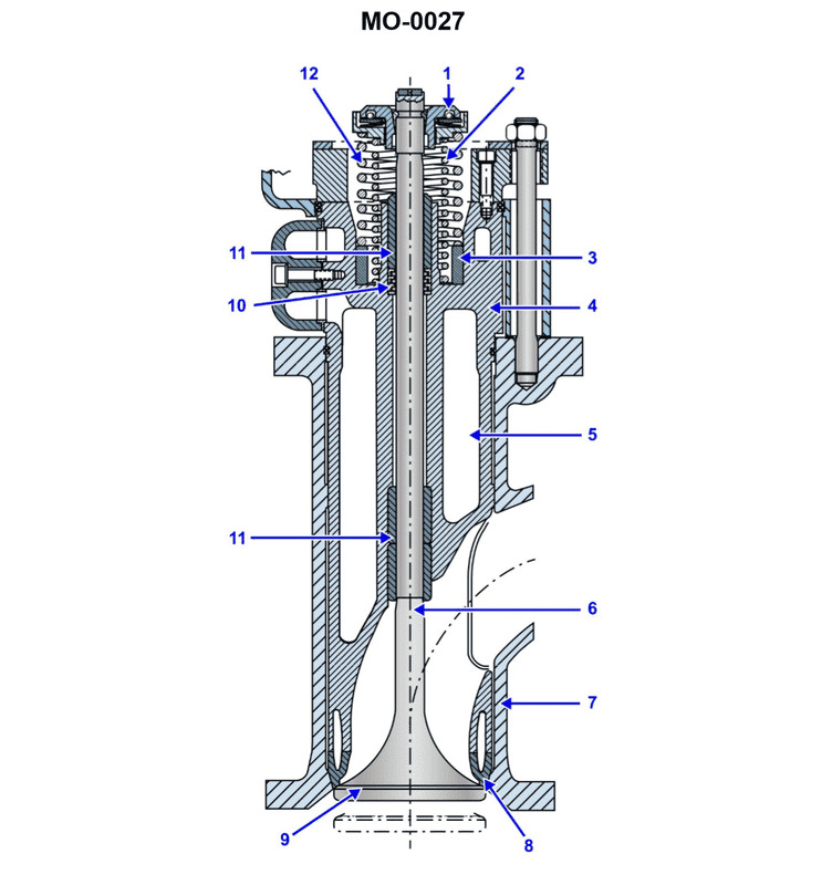
Question 494
Question: Excessive wear at part No.11, shown in the illustration would result in _______________. Illustration MO-0027
A. improper timing
B. increased oil consumption
C. lost compression
D. low oil pressure
The correct answer is B) increased oil consumption. Excessive wear at part No. 11, which is likely a component of the engine's lubrication system, would result in increased oil consumption. When engine parts experience excessive wear, it can lead to oil leaks or reduced oil sealing, causing the engine to consume more oil than normal. This is because the worn parts are no longer able to contain the oil within the engine's internal components effectively. The other options are incorrect because: A) improper timing is not directly related to excessive wear at part No. 11, C) lost compression is more likely due to issues with the engine's cylinder or piston sealing, and D) low oil pressure is a symptom that could result from the increased oil consumption, but is not the direct cause.
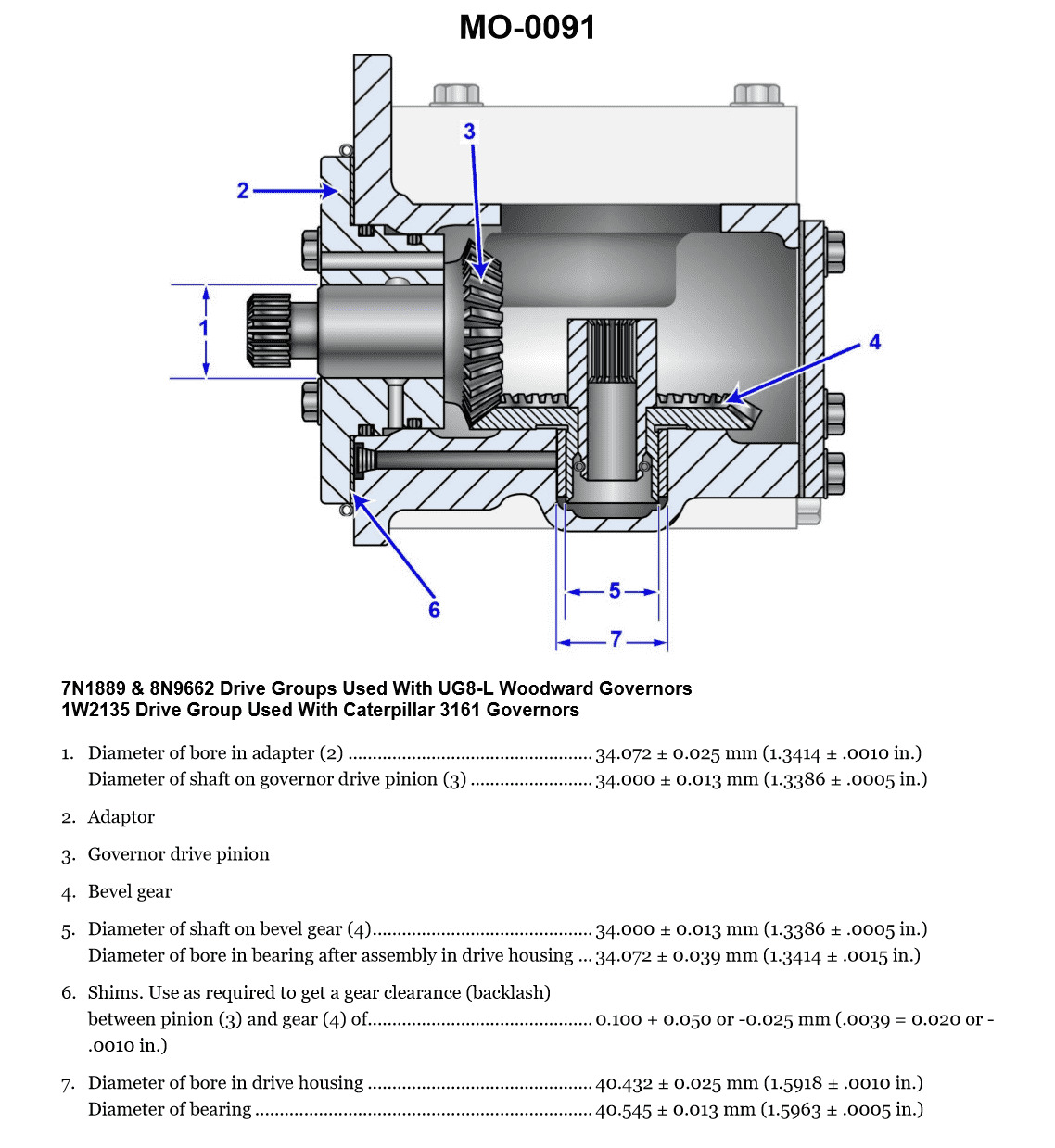
Question 495
Question: The gear drive, shown in the illustration, can have the backlash determined best by using a_______________. Illustration MO-0091
A. lead wire
B. feeler gauge
C. lash indicator
D. red dye indicator
The correct answer is B) feeler gauge. A feeler gauge is the best tool to determine the backlash in a gear drive, as it allows for precise measurement of the clearance between the gear teeth. Backlash is the amount of play or looseness in the gear system, and it needs to be within the manufacturer's specified limits to ensure proper gear operation and prevent excessive wear. The other options are not as suitable for accurately measuring backlash. Lead wire and lash indicators are not designed for this specific purpose, and a red dye indicator would not provide a quantitative measurement of the backlash.
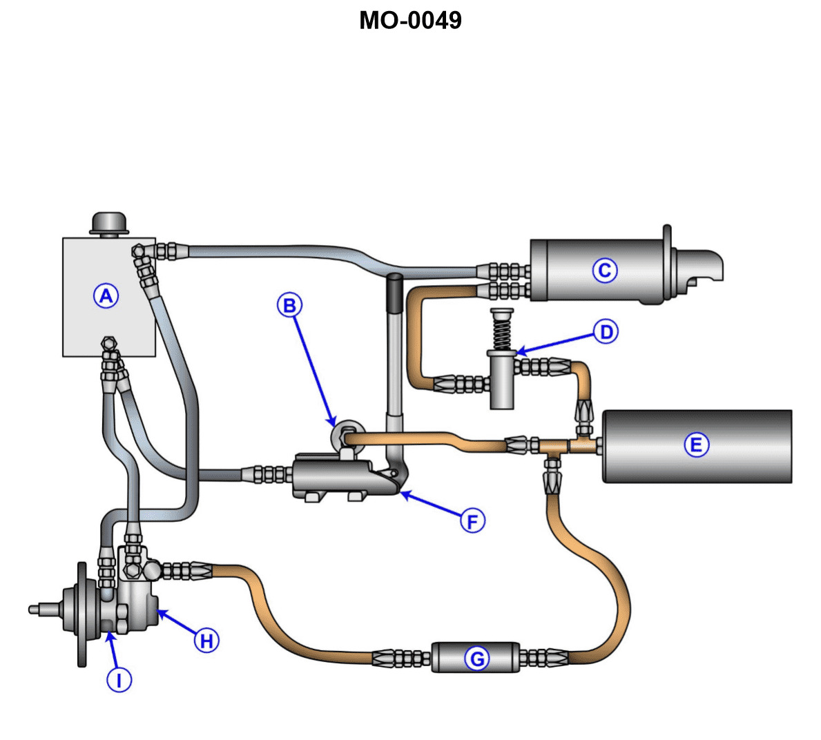
Question 507
Question: The starter control valve in the hydraulic system shown in the illustration is malfunctioning. Before removing the valve, you must first_______________. Illustration MO-0049
A. drain the reservoir
B. remove all plugs from the system
C. bleed off all accumulator pressure in "E"
D. ensure that the accumulator piston is in the charged position
The correct answer is C) bleed off all accumulator pressure in "E". Before removing the starter control valve, it is important to bleed off any accumulated pressure in the hydraulic system. This is necessary to prevent sudden release of stored energy, which could be dangerous during the valve removal process. Releasing the pressure in the accumulator ("E" in the illustration) will ensure a safe and controlled environment for the valve removal and maintenance. The other options are incorrect because: A) draining the reservoir may not be necessary if the accumulator pressure is properly bled off; B) removing all plugs is not required for this specific task; and D) ensuring the accumulator piston is in the charged position does not address the need to release the pressure before valve removal.