Pass Your Coast Guard Licensing Exams!
Study offline, track your progress, and simulate real exams with the Coast Guard Exams app
Motor Plants - 1st Asst/Chief
74 images
Question 4
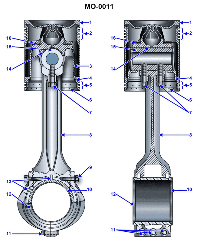
Question: Which construction detail is apparent in the connecting rod and piston assembly shown in the illustration? Illustration MO-0011
A. The piston is designed with a heat dam.
B. It is a fork assembly.
C. The piston is water cooled.
D. The wrist pin is free floating.
The correct answer is A) The piston is designed with a heat dam. The heat dam is a construction detail commonly found in marine diesel engine pistons. It is a step or shoulder machined into the piston crown that helps to reduce the transfer of heat from the combustion chamber into the piston, thus improving the piston's thermal efficiency and durability. The other options are incorrect because: B) A fork assembly refers to a specific type of connecting rod design, not a piston detail; C) Water cooling is a method of cooling the engine block, not the piston itself; and D) A free-floating wrist pin is a separate design feature not necessarily related to the piston construction.
Question 6
Question: The diesel engine shown in the illustration utilizes the type of cylinder construction identified as_______________. Illustration MO-0007
A. a dry liner
B. a wet liner
C. integral with a removable sleeve
D. integral with a non-removable sleeve
The correct answer is B) a wet liner. In a wet liner cylinder construction, the cylinder liner is in direct contact with the cooling system, allowing for better heat transfer and cooling of the cylinder. This design is commonly used in diesel engines, as it helps to manage the high temperatures and pressures generated during the combustion process. The other options are incorrect because: A) a dry liner is not in direct contact with the cooling system, C) a removable sleeve is not the same as a wet liner, and D) a non-removable sleeve is also not the same as a wet liner.
Question 7
Question: Which of the following statements is correct concerning the connecting rod and piston assembly shown in the illustration? Illustration MO-0011
A. The piston is free to rotate on the carrier thrust washer.
B. The piston pin is bolted to the connecting rod.
C. The piston has a heat dam.
D. All of the above.
The correct answer is D) All of the above. The illustration shows a typical piston and connecting rod assembly, and all the statements in the answer choices are correct: A) The piston is free to rotate on the carrier thrust washer, which allows the piston to align properly with the cylinder walls during engine operation. B) The piston pin is bolted or secured to the connecting rod, which transfers the force from the piston to the crankshaft. C) The piston has a heat dam, which is a design feature that helps dissipate heat from the piston to prevent damage from excessive temperatures. Therefore, all the statements described in the answer choices are accurate representations of the components shown in the illustration.
Question 17
Question: If a valve seat insert, similar to that shown in the illustration is cracked, this may be indicated by_______________. Illustration MO-0043
A. white vapor in the exhaust gas
B. high exhaust pyrometer readings on that particular cylinder
C. continuous spring surge
D. a jammed indicator cock
The correct answer is A) white vapor in the exhaust gas. If a valve seat insert is cracked, it can cause combustion gases to leak past the valve, resulting in white vapor or steam in the exhaust. This is because the cracked valve seat allows unburnt fuel and air to escape the cylinder, producing the visible white vapor in the exhaust. The other options are incorrect because: B) high exhaust pyrometer readings would indicate a problem with that cylinder's thermal efficiency, not necessarily a cracked valve seat; C) continuous spring surge is more likely caused by a mechanical issue like a stuck valve, not a cracked valve seat; and D) a jammed indicator cock is a separate issue not directly related to a cracked valve seat.
Question 19
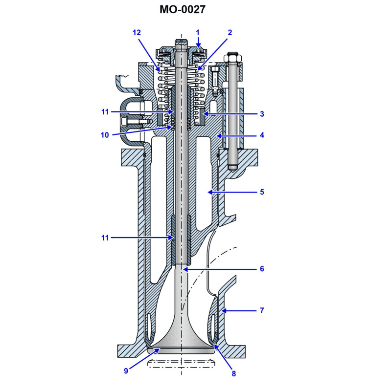
Question: Excessive wear at part #11, as shown in the illustration, would result in_______________. Illustration MO-0027
A. improper timing
B. increased oil consumption
C. lost compression
D. low oil pressure
The correct answer is B) increased oil consumption. Explanation: Part #11 in the illustration is likely a component of the engine, such as a piston or valve. Excessive wear at this part would result in increased oil consumption because the worn components would allow more oil to pass through the engine, leading to higher overall oil usage. The other answer choices (improper timing, lost compression, low oil pressure) are not directly related to the issue of increased oil consumption caused by excessive wear of a specific engine part.
Question 24
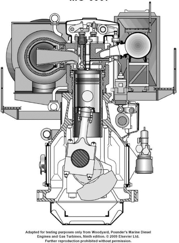
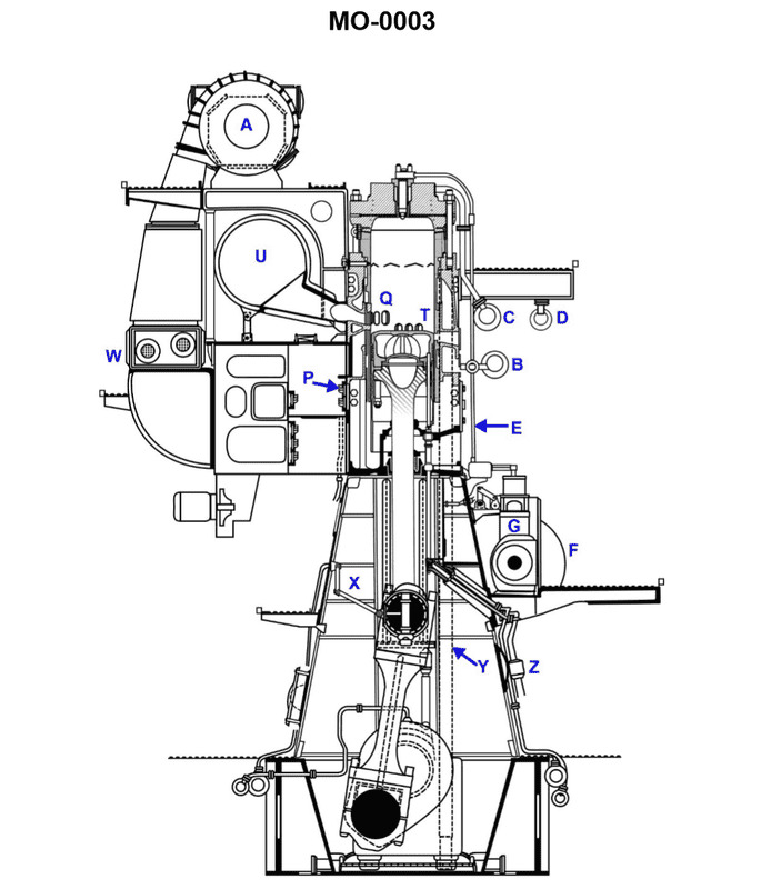
Question: In the illustrated engine, the main camshaft controls the timing of which of the following components? Illustration MO-0003
A. exhaust valves
B. fuel pumps
C. Intake valves
D. all of the above
The correct answer is B) fuel pumps. The main camshaft in the illustrated engine controls the timing of the fuel pumps. The camshaft is responsible for opening and closing the fuel pumps at the proper times to deliver fuel to the engine cylinders. The camshaft does not directly control the opening and closing of the exhaust valves (option A) or intake valves (option C), as those are typically controlled by separate camshafts or rockers. Option D is incorrect because the main camshaft does not control all of those components, only the fuel pumps.
Question 27
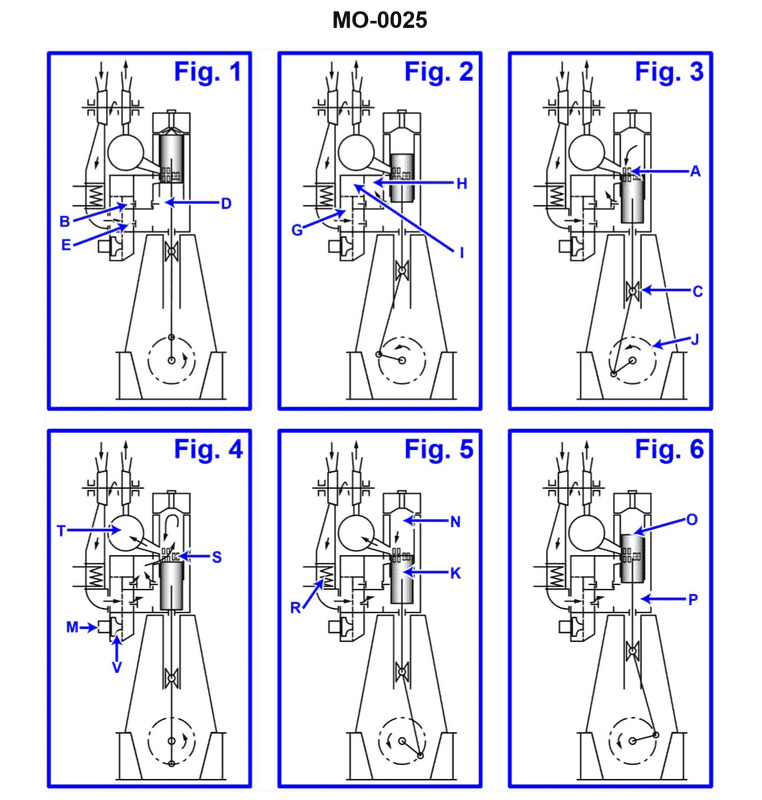
Question: In what figure of the illustration does the crosshead experience the greatest side thrust? Illustration MO-0025
A. Figure 1
B. Figure 2
C. Figure 5
D. Figure 6
The correct answer is B) Figure 2. In the illustration MO-0025, the crosshead experiences the greatest side thrust in Figure 2. This is because the connecting rod is offset from the centerline of the cylinder, creating a side thrust on the crosshead as the piston travels. The other figures do not show this offset arrangement, and therefore the crosshead would not experience as much side thrust. The other answer choices are incorrect because: A) Figure 1 does not show the offset connecting rod arrangement. C) Figure 5 does not show the offset connecting rod arrangement. D) Figure 6 does not show the offset connecting rod arrangement.
Question 28
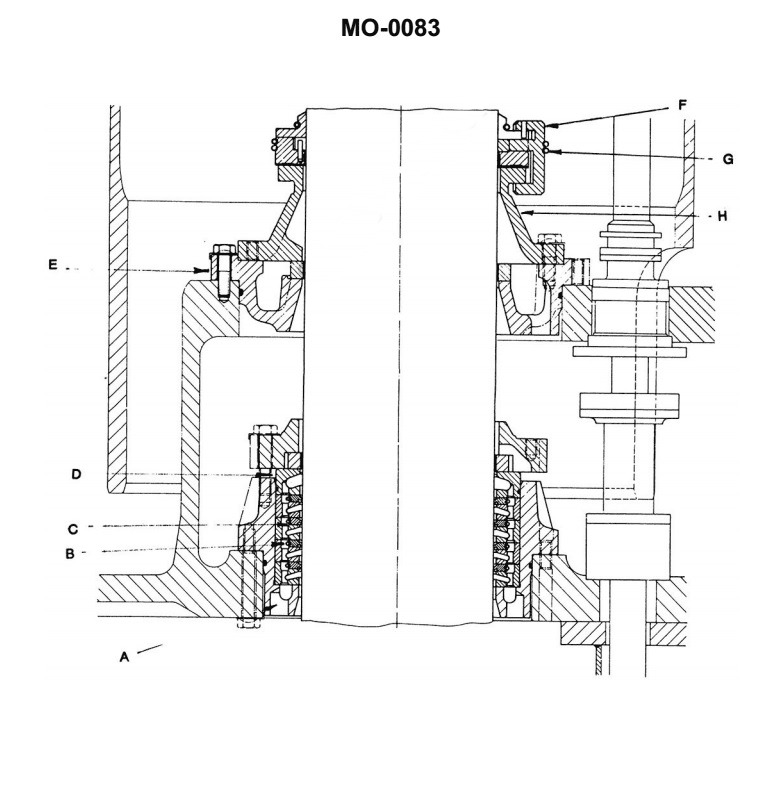
Question: There are two glands provided where the piston rod exits the cylinder shown in the illustration. The purpose of the top gland is to_______________. Illustration MO-0083
A. prevent crankcase oil leaking out
B. seal against scavenge air leakage
C. maintain crankcase vacuum
D. maintain crankcase pressure
The correct answer is B) seal against scavenge air leakage. The top gland where the piston rod exits the cylinder is designed to seal against the leakage of scavenge air, which is the air that is used to purge the cylinder and remove the exhaust gases. This seal is necessary to maintain the proper air/fuel mixture and combustion efficiency within the engine. The other answer choices are incorrect because: A) the crankcase oil leakage is typically sealed by the crankshaft seals, not the piston rod gland; C) and D) the piston rod gland does not directly maintain the crankcase vacuum or pressure, which are controlled by other engine components.
Question 29
Question: The lower end of the piston rod, shown in the illustration, is fitted into the_______________. Illustration MO-0003
A. crankpin
B. crosshead
C. piston pin
D. crosshead guide
The correct answer is B) crosshead. The lower end of the piston rod is fitted into the crosshead, which is a mechanical component that connects the piston rod to the crankshaft. The crosshead acts as an intermediary between the reciprocating motion of the piston and the rotational motion of the crankshaft, helping to transmit the power from the piston to the crankshaft. The other options are incorrect because: A) the crankpin is the journal on the crankshaft that the connecting rod is attached to, not the piston rod; C) the piston pin connects the piston to the connecting rod, not the piston rod; and D) the crosshead guide is a stationary component that the crosshead slides along, not the component the piston rod is connected to.
Question 30
Question: If the speed of the propeller is 135 RPM, the speed of the engine camshaft shown in the illustration will be_______________. Illustration MO-0003
A. 135 RPM
B. 270 RPM
C. variable depending on the camshaft gear train gear ratios
D. variable depending on the ratio between engine rpm and propeller shaft rpm
The correct answer is A) 135 RPM. In a marine engine, the speed of the camshaft is directly linked to the speed of the crankshaft, which in turn is directly linked to the speed of the propeller. Since the propeller speed is given as 135 RPM, the speed of the engine camshaft will also be 135 RPM, as they are directly connected through the engine's internal gearing. The other options are incorrect because B) 270 RPM would be twice the propeller speed, which is not the case, and C) and D) suggest the camshaft speed could be variable, when in fact it is directly proportional to the propeller speed in a fixed gear ratio.
Question 31
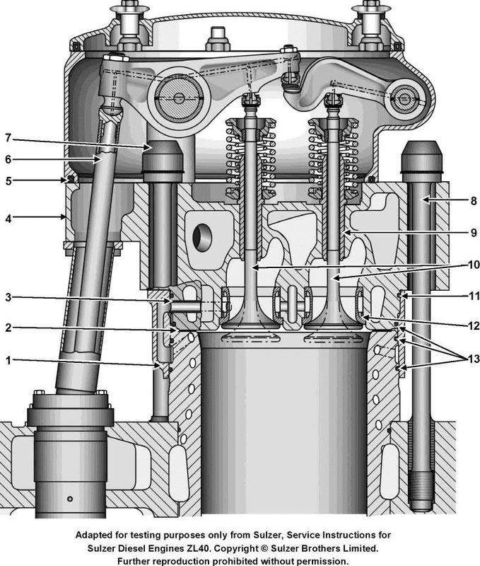
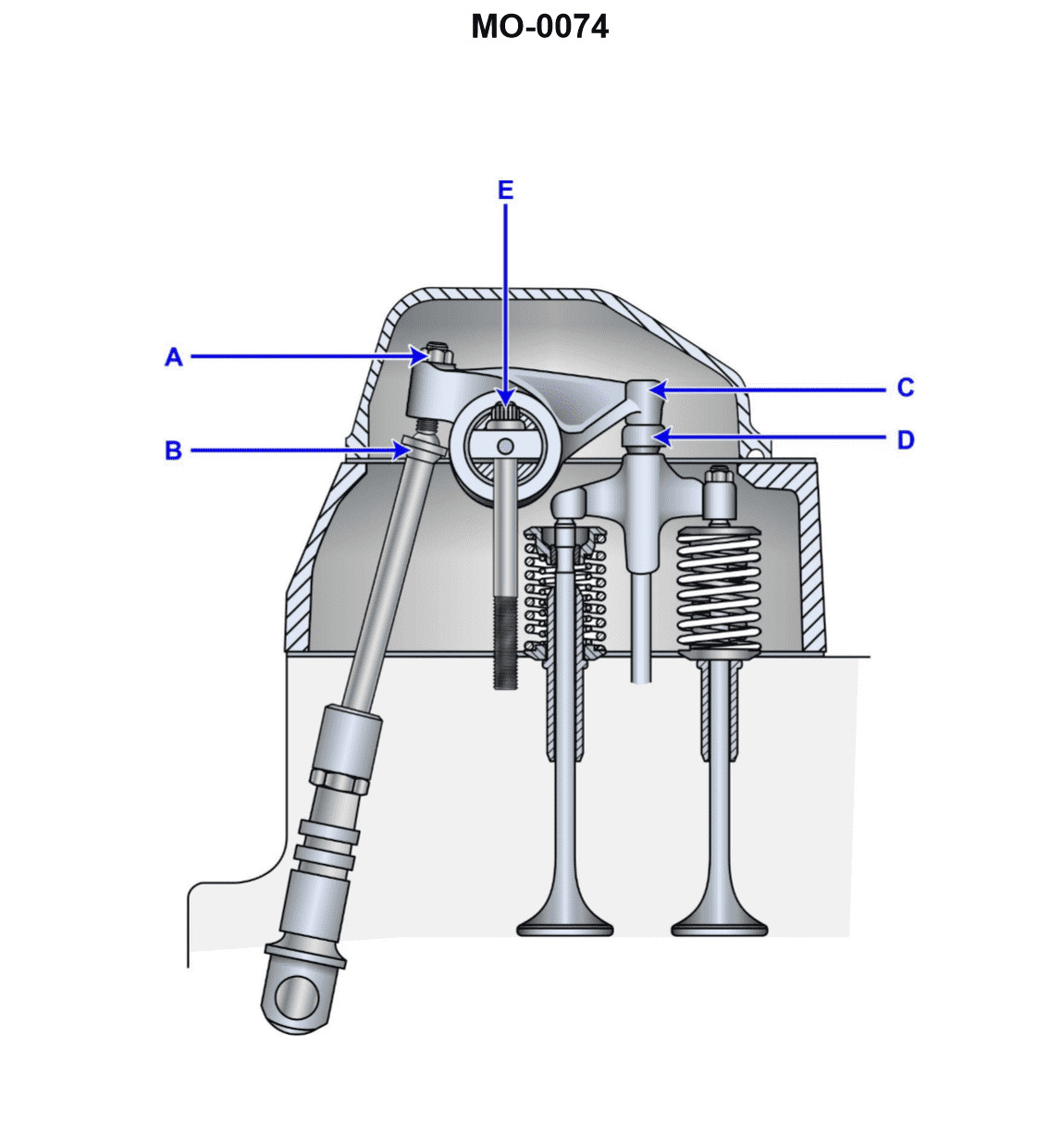
Question: Which of the following statements would apply when checking the valve clearance of the unit shown in the illustration? Illustration MO-0074
A. The valve is mechanically adjusted at point "D".
B. The valve is mechanically adjusted at point "E".
C. Tappet clearance is measured between points "A" and "B".
D. Cold valve clearance is measured between components "C" and "D".
The correct answer is D) Cold valve clearance is measured between components "C" and "D". The valve clearance is typically measured between the rocker arm (C) and the valve stem (D) when the engine is cold. This ensures that the correct clearance is set to allow for thermal expansion of the components during engine operation. The other answer choices are incorrect because they do not correctly identify the components involved in measuring the valve clearance on this type of engine setup.
Question 32
Question: When inspecting the valve mechanism shown in the illustration, normal maintenance would include_______________. Illustration MO-0074
A. mechanically adjusting the valve at point "D"
B. mechanically adjusting the valve at point "E"
C. changing the tappet clearance as measured between points "A" and "B"
D. measuring the cold valve clearance between components "C" and "D"
The correct answer is D) measuring the cold valve clearance between components "C" and "D". The normal maintenance for the valve mechanism shown in the illustration MO-0074 would involve measuring the cold valve clearance between the valve stem (component C) and the valve tappet (component D). This is a standard procedure to ensure the proper operation of the valve mechanism and prevent any issues related to incorrect valve clearance. The other options are incorrect because they do not address the specific maintenance task required for this valve mechanism. Mechanically adjusting the valve at points "D" or "E" would not be part of the normal maintenance, and changing the tappet clearance between points "A" and "B" is not the appropriate action to take.
Question 42
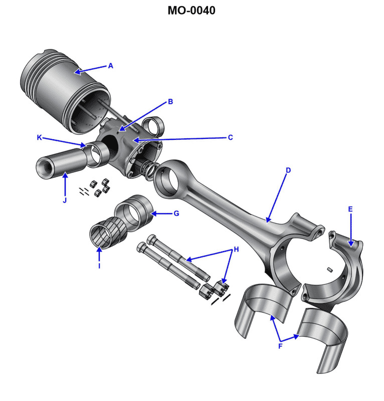
Question: The part labeled "G", as shown in the illustration, is a_______________. Illustration MO-0040
A. connecting rod cap
B. bearing shell
C. connecting rod bushing
D. piston bushing
The correct answer is C) connecting rod bushing. The connecting rod bushing is the part labeled "G" in the illustration MO-0040. The connecting rod bushing is a crucial component that connects the connecting rod to the crankshaft, allowing the smooth rotation of the engine. It provides a bearing surface between the two parts, enabling the efficient transfer of power from the piston to the crankshaft. The other options are incorrect because: A) a connecting rod cap is a separate component that secures the connecting rod to the crankshaft, B) a bearing shell is a different part that supports the crankshaft, and D) a piston bushing is a separate component that guides the piston within the cylinder.
Question 45
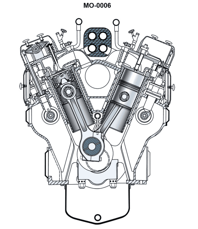
Question: In the auxiliary diesel engine, shown in the illustration, the_______________. Illustration MO-0006
A. governor is linked to the fuel injection pump by vertical linkage
B. explosion relief doors are clearly visible on both sides of the crankcase
C. camshaft rotates at the same speed as the crankshaft
D. engine oil filter is outboard of the electric starter
The correct answer is A) the governor is linked to the fuel injection pump by vertical linkage. In an auxiliary diesel engine, the governor is responsible for regulating the engine's speed and fuel delivery. The governor is directly connected to the fuel injection pump via a vertical linkage, which allows the governor to adjust the fuel supply to the engine in response to changes in load or speed. The other answer choices are incorrect because: B) the explosion relief doors are not clearly visible in the given illustration, C) the camshaft typically rotates at half the speed of the crankshaft in a four-stroke diesel engine, and D) the engine oil filter is usually located near the engine block, not outboard of the electric starter.
Question 50
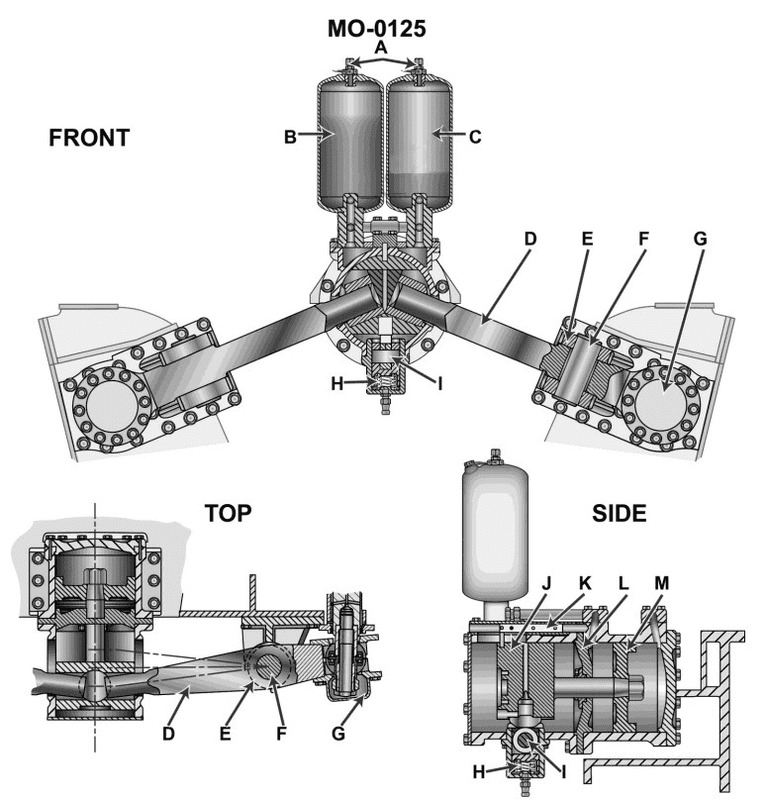
Question: The cylinders labeled "B" and "C" in the illustration are used to_______________. Illustration MO-0125
A. supply a specific volume of oil to the engine governor
B. provide oil to lubricate component "F"
C. provide the required quantity of grease at specified maintenance intervals
D. supply the force required to shift the engine camshafts axially to reverse engine rotation
The correct answer is D) supply the force required to shift the engine camshafts axially to reverse engine rotation. This is correct because the cylinders labeled "B" and "C" in the illustration are typically used to provide the hydraulic force necessary to shift the engine camshafts axially, which allows the engine to be operated in reverse. This is a common feature in marine engines to enable maneuvering and docking of vessels. The other options are incorrect because they do not accurately describe the function of the cylinders "B" and "C" in the illustration. Option A refers to the engine governor, which is a separate system. Option B refers to lubricating a component "F", which is not mentioned in the question. Option C describes a greasing function, which is also unrelated to the cylinders in the illustration.
Question 51
Question: The component labeled "A" on the engine reversing device shown in the illustration, performs its function by transmitting. Illustration MO-0125
A. a hydraulic pressure which shifts an alternate set of camshaft followers to ride on the engine camshaft
B. an electric voltage which energizes solenoids to de-clutch the engine
C. a fuel oil pressure signal which reverses the engine governor control cylinder
D. a pneumatic signal which activates a hydraulic control cylinder allowing the camshaft to shift axially
The correct answer is D) a pneumatic signal which activates a hydraulic control cylinder allowing the camshaft to shift axially. The component labeled "A" on the engine reversing device is responsible for transmitting a pneumatic signal that activates a hydraulic control cylinder. This allows the camshaft to shift axially, which is the key function of the engine reversing device in order to reverse the direction of the engine. The other answer choices are incorrect because they do not accurately describe the mechanism of the engine reversing device. Options A, B, and C involve different methods of engine control that are not relevant to the specific component and function described in the question.
Question 61
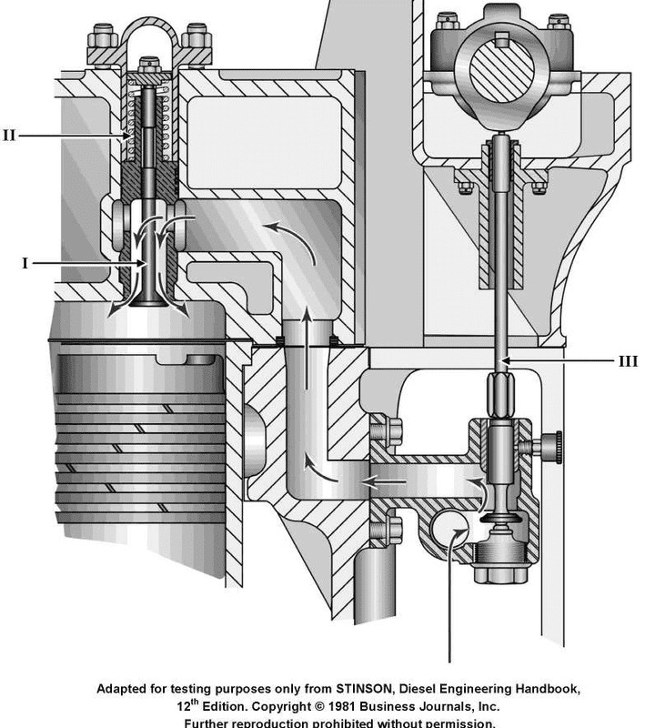
Question: During the starting of a diesel engine, compression gases are prevented from backing into the air starting system, shown in the illustration, by the_______________. Illustration MO-0046
A. cylinder air starting check valves
B. air starting control valve
C. individual distribution valves
D. high-pressure in the starting air manifold
The correct answer is A) cylinder air starting check valves. During the starting of a diesel engine, the compression gases are prevented from backing into the air starting system by the cylinder air starting check valves. These one-way valves allow air to flow from the air starting system into the engine cylinders, but prevent the compressed gases from the engine from flowing back into the air starting system. This protects the air starting system from any potential damage or interference. The other options are incorrect because: B) the air starting control valve is responsible for regulating the air supply to the engine, not preventing backflow; C) the individual distribution valves distribute the starting air to the individual cylinders, but do not prevent backflow; and D) the high pressure in the starting air manifold alone does not prevent the compression gases from backing into the air starting system.
Question 63
Question: Which of the following statements is true concerning the air starting valve, labeled "III", as shown in the illustration? Illustration MO-0046
A. When starting, the air starting valve is held open by air pressure.
B. When starting air is secured, the air starting valve is closed.
C. During normal engine running, the air starting valve opens and closes constantly due to cam action.
D. The air starting valve is opened by cam action.
The correct answer is D) The air starting valve is opened by cam action. The air starting valve labeled "III" in the illustration is typically part of the engine's starting system. When the engine is being started, the air starting valve is opened by cam action, allowing compressed air to flow into the engine's cylinders and facilitate the starting process. This is the normal operation of the air starting valve during engine startup. The other answer choices are incorrect because: A) The air starting valve is not held open by air pressure when starting, but rather by cam action. B) The air starting valve is closed when starting air is secured, not opened. C) The air starting valve does not open and close constantly during normal engine running, but rather is opened only during the starting process.
Question 65
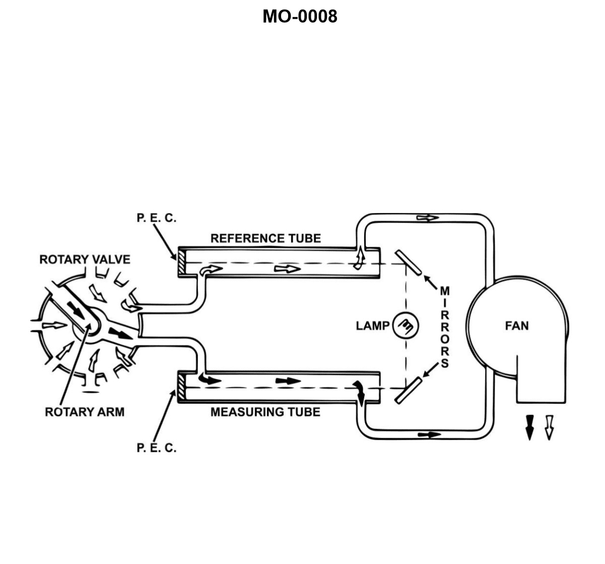
Question: The device shown in the illustration is a_______________. Illustration MO-0008
A. level type explosimeter, for small medium-speed, trunk type piston engines
B. rotary type mist detector, designed for use in four-stroke, high-speed diesel engines
C. comparator type mist detector for large low-speed, crosshead type engines
D. photoelectric, explosive gas indicator, for use in high-speed, two-stroke, trunk type piston engines
The correct answer is C) comparator type mist detector for large low-speed, crosshead type engines. This is the correct answer because the illustration MO-0008 depicts a comparator type mist detector, which is a device designed for use in large, low-speed, crosshead type diesel engines. Comparator type mist detectors are specifically used to monitor the oil mist in the crankcase of these types of engines, which are commonly found in large ships and vessels. The other answer choices are incorrect because they describe different types of devices (level type explosimeter, rotary type mist detector, and photoelectric explosive gas indicator) that are not depicted in the illustration and are not typically used in the same applications as a comparator type mist detector.
Question 67
Question: The device shown in the illustration is classified as a/an_______________. Illustration MO-0008
A. comparator type mist detector
B. Ringelmann exhaust gas analyzer
C. reflective type explosion meter
D. exhaust gas vapor condenser
The correct answer is A) comparator type mist detector. A comparator type mist detector is a device used to detect the presence and concentration of mist or fog in the atmosphere. This type of device is often used in marine applications, such as on ships and boats, to monitor environmental conditions and ensure safe navigation. The other answer choices are incorrect because: B) Ringelmann exhaust gas analyzer is used to measure the opacity of exhaust emissions, not mist or fog. C) reflective type explosion meter is used to detect the presence of explosive gases, not mist or fog. D) exhaust gas vapor condenser is used to remove water vapor from exhaust gases, not to detect mist or fog.
Question 68
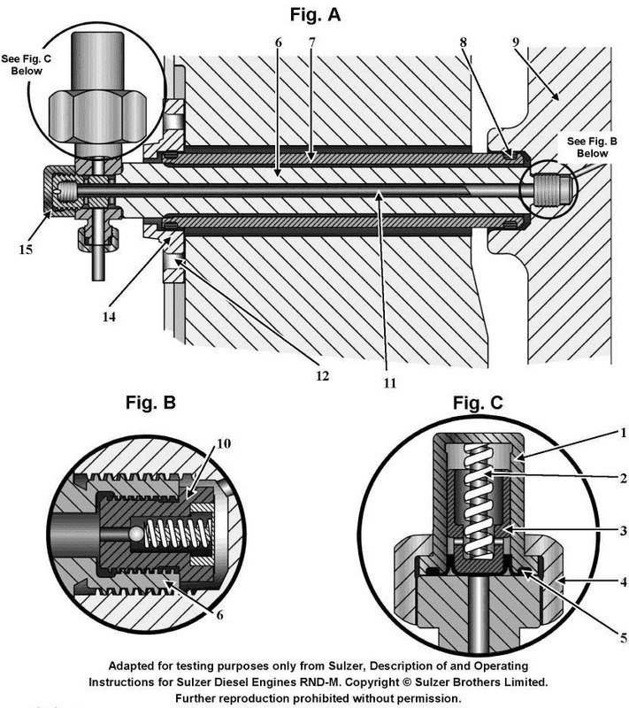
Question: The device shown in figure "A" of the illustration is used to _______________. Illustration MO-0042
A. admit starting air to the cylinder
B. provide lubrication to the cylinder
C. inject fuel into the cylinder
D. provide an adapter to obtain combustion pressure readings
The correct answer is B) provide lubrication to the cylinder. The device shown in figure "A" of the illustration MO-0042 is likely a lubricator, which is used to provide lubrication to the cylinder. This is necessary to reduce friction and wear on the internal components of the engine, ensuring proper operation and prolonging the engine's lifespan. The other answer choices are incorrect because: A) admits starting air to the cylinder, C) injects fuel into the cylinder, and D) provides an adapter to obtain combustion pressure readings, which are not the primary function of the device shown in the illustration.
Question 69
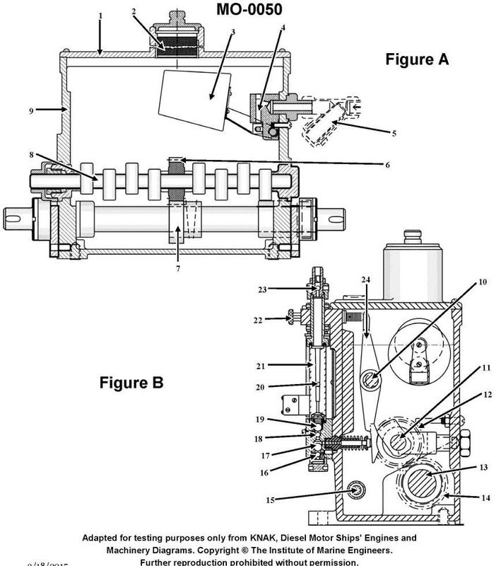
Question: The illustrated device is used to_______________. Illustration MO-0050
A. supply cylinder lubricating oil to the engine
B. actuate exhaust valves in the correct sequence
C. meter fuel oil to the injectors
D. admit the correct amount of starting air to the cylinders in proper order
The correct answer is A) supply cylinder lubricating oil to the engine. This device is likely a lubricating oil pump, which is responsible for delivering the necessary lubricating oil to the engine's cylinders and other moving parts. Ensuring proper lubrication is crucial for the engine's operation and longevity. The other answer choices are incorrect because they do not accurately describe the function of this particular device. Option B refers to exhaust valve actuation, option C is for fuel metering, and option D is for starting air admission - none of which match the primary purpose of a lubricating oil pump.
Question 96
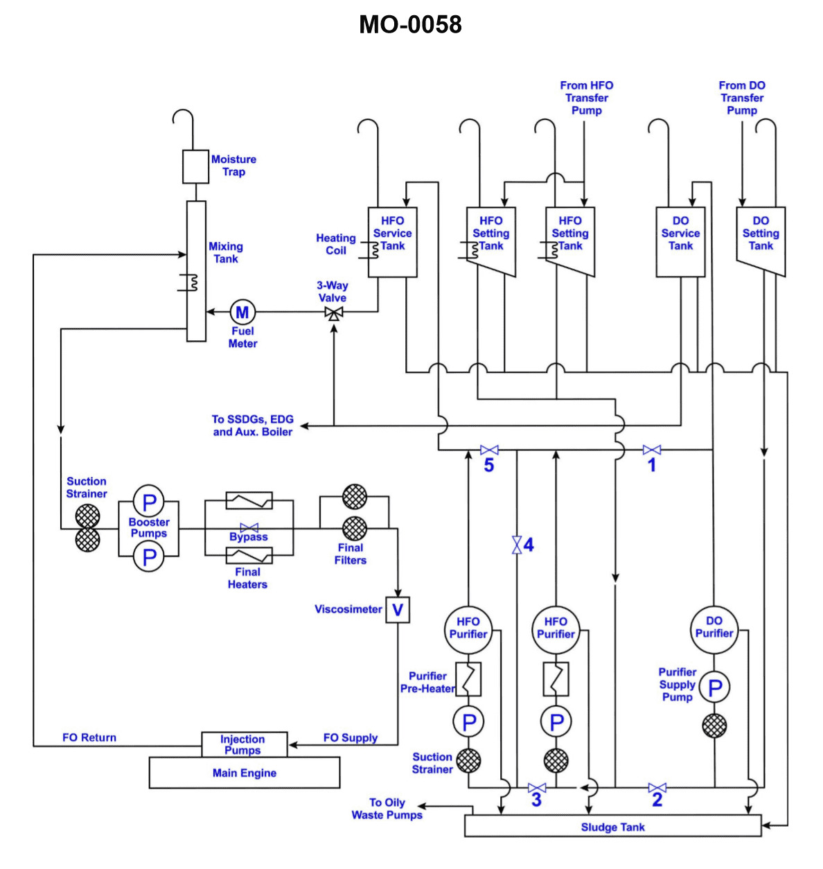
Question: The purpose of the interlocked three-way valve shown in the illustration is to _______________. Illustration MO-0058
A. control the rate of fuel oil flow to the engines
B. change fuel from heavy to light oil or vice-versa while insuring that oil is returned to the proper day tank
C. act as an emergency fuel shut off, regardless of the fuel being used
D. recirculate fuel through the heater during warm-up
The correct answer is B) change fuel from heavy to light oil or vice-versa while ensuring that oil is returned to the proper day tank. The purpose of the interlocked three-way valve is to allow the operator to switch between different types of fuel oil (heavy or light) while ensuring that the fuel is returned to the correct day tank. This prevents cross-contamination of the fuel and maintains the proper fuel supply for the engines. The other answer choices do not accurately describe the primary function of this type of valve in a marine fuel system.
Question 97
Question: Heavy fuel oil used in the system shown in the illustration, will have the lowest viscosity. Illustration MO-0058
A. at the transfer pump discharge
B. in the settling tank
C. in the three-way valve
D. at the main engine fuel oil header
The correct answer is D) at the main engine fuel oil header. Heavy fuel oil used in the system shown in the illustration will have the lowest viscosity at the main engine fuel oil header. This is because as the fuel oil flows through the system, it is heated and its viscosity is reduced. The lowest viscosity point will be at the final stage, which is the main engine fuel oil header, just before the fuel is injected into the engine. The other options are incorrect because the fuel oil will have a higher viscosity at the transfer pump discharge, in the settling tank, and in the three-way valve, as it has not yet been fully heated and processed through the system.
Question 98
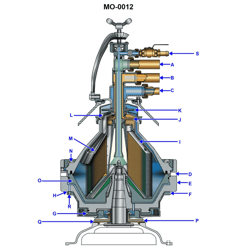
Question: The greatest difference between the centrifuge bowl shown in the illustration and that of a tubular bowl, with straight, vertical, interior surfaces, is that the illustrated unit_______________. Illustration MO-0012
A. does not require a discharge ring when operated as a separator
B. rotates at 1000 rpm slower than the old tubular bowl type
C. rotates at 1000 rpm higher than the old tubular bowl type
D. is self desludging
The correct answer is D) is self desludging. The key difference between the centrifuge bowl shown in the illustration and a traditional tubular bowl is that the illustrated unit has a conical shape, rather than straight, vertical interior surfaces. This conical shape allows the bowl to be self-desludging, meaning it can continuously remove accumulated solids (sludge) without needing to be shut down for manual cleaning. The other answer choices are incorrect because: A) the discharge ring is still required, B) the rotational speed is not specified, and C) there is no information provided about the rotational speed difference compared to the old tubular bowl.
Question 99
Question: The temperature of the contaminated fuel oil fed to the centrifuge shown in the illustration should be_______________. Illustration MO-0012
A. 160°F to 180°F
B. 203°F to less than 212°F
C. greater than 212°F
D. selected according to the oil's viscosity index
The correct answer is B) 203°F to less than 212°F. This temperature range is typically required for the contaminated fuel oil fed to a centrifuge, as it helps maintain the proper viscosity for effective separation of contaminants. Fuel oils need to be heated to a specific temperature, usually between 203°F and just below the boiling point of 212°F, to reduce their viscosity and enable the centrifuge to efficiently remove water, sludge, and other impurities. The other options are incorrect because: A) 160°F to 180°F may be too low to achieve the necessary viscosity reduction, C) greater than 212°F could cause the fuel to vaporize, and D) selecting the temperature based solely on the viscosity index, without considering the centrifuge's operational requirements, would not be the most appropriate approach.
Question 100
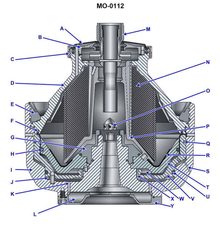
Question: What terminates the sludge discharge cycle of the device shown in the illustration? Illustration MO-0112
A. The solenoid valve opens, directs high-pressure fluid into the closing chamber, and results in an upward movement of the sliding piston.
B. The solenoid valve closes, reduces the water pressure to the paring chamber, and allows the spring force to move the sliding piston upward.
C. The solenoid valve closes, allows the weight of the sliding piston to oppose the low water pressure, and moves it along the axis of the spindle.
D. The solenoid valve closes, allows the water in the opening chamber to bleed off through "S", and the sliding piston moves upward due to the force developed in area "J".
The correct answer is D. The solenoid valve closing allows the water in the opening chamber to bleed off through "S", which allows the sliding piston to move upward due to the force developed in area "J". This is the mechanism that terminates the sludge discharge cycle of the device shown in the illustration. The other options are incorrect because: A) This would describe the opening cycle, not the termination of the sludge discharge cycle. B) The reduction in water pressure to the paring chamber would not directly cause the sliding piston to move upward. C) The weight of the sliding piston alone would not be sufficient to overcome the low water pressure and move it along the axis of the spindle.
Question 101
Question: The area indicated by the letter "W", shown in the illustration is correctly termed the . Illustration MO-0112
A. upper sliding piston chamber
B. closing chamber
C. opening chamber
D. parting chamber
The correct answer is C) opening chamber. The "W" in the illustration MO-0112 is correctly referred to as the opening chamber. This is the chamber in a marine engine where the intake of the air-fuel mixture occurs, allowing it to enter the cylinder during the opening of the intake valve. This opening chamber is a critical part of the engine's operation, as it facilitates the proper intake of the air-fuel mixture, which is then compressed and ignited to generate power. The other answer choices are incorrect because they do not accurately describe the specific component indicated by the letter "W" in the illustration. The upper sliding piston chamber, closing chamber, and parting chamber are not the correct terms for this particular engine component.
Question 102
Question: The device labeled "D", as shown in the illustration, is the bowl_______________. Illustration MO-0112
A. top
B. hood
C. hub
D. cover
The correct answer is A) top. The device labeled "D" in the illustration MO-0112 is the bowl top. This is the correct answer based on the standard terminology used in the US Coast Guard Captain's License Examinations to describe the components of a marine engine. The bowl top, also known as the air intake housing or air cleaner cover, is the removable upper part of the air intake system that covers the air filter or air cleaner element. The other answer choices are incorrect because the "hood" (B) is not a standard term used to describe this component, the "hub" (C) refers to a different part of the engine, and the "cover" (D) is too generic and does not specifically identify the bowl top.
Question 107
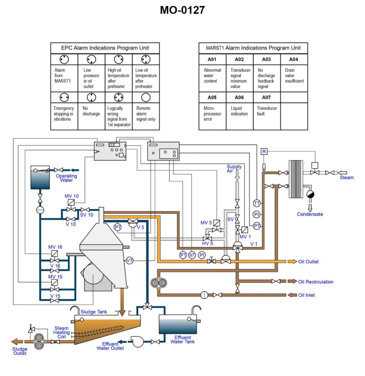
Question: Which of the following precautions should be taken prior to starting the separator shown in the illustration? Illustration MO-0127
A. Check for the correct oil level in the gear housing.
B. Make sure the separator is properly assembled.
C. Release the bowl brake and confirm proper valve line up.
D. All of the above are correct.
The correct answer is D) All of the above are correct. This is the correct answer because before starting a separator, it is important to take all of the listed precautions: 1) Check the oil level in the gear housing to ensure proper lubrication. 2) Ensure the separator is properly assembled to prevent leaks or malfunctions. 3) Release the bowl brake and confirm the valve lineup is correct to allow proper operation of the separator. Taking these three steps helps ensure the separator is in proper working order and will function safely and effectively when started. The other answer choices are incorrect because they do not cover all the necessary precautions that should be taken.
Question 111
Question: After removing the bowl hood of the device shown in the illustration, excessive quantities of sludge are visible. Which of the following statements represents the approach to rectify the situation? Illustration MO-0112
A. Remove only the disc stack, separate all the discs, clean with steel wool and solvent, replace the disc stack ensuring it is located by use of the dowel pin shown.
B. Disassemble the entire unit, clean all components, replace all defective discs and use the proper lubricant where required.
C. Steam clean the components in place, check for proper alignment, using the match marks provided, reassemble and restart the unit.
D. Disassemble the entire unit, clean all components, replace any defective gaskets and use the proper lubricants where required.
The correct answer is D) Disassemble the entire unit, clean all components, replace any defective gaskets and use the proper lubricants where required. This is the correct approach because excessive sludge buildup in the device indicates a need for a thorough disassembly, cleaning, and replacement of any worn or damaged components. Merely removing and cleaning the disc stack (option A) or steam cleaning in place (option C) would not adequately address the root cause of the sludge buildup. Disassembling the entire unit and replacing any defective gaskets, in addition to cleaning all components and using the proper lubricants, is the comprehensive approach required to rectify the situation. The other options, while potentially addressing some aspects of the problem, do not encompass the full scope of actions necessary to properly resolve the excessive sludge buildup.
Question 112
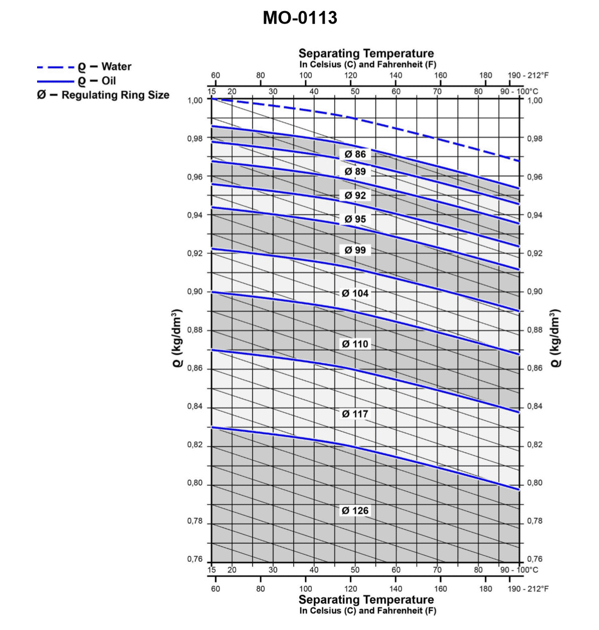
Question: Using the graph shown in the illustration, the oil being separated has a specific gravity of 0.87 kg/dm3 at 72.5°C. What will be the specific gravity if the temperature is lowered to 40°C? Illustration MO-0113
A. 0.872 kg/dm3
B. 0.882 kg/dm3
C. 0.892 kg/dm3
D. 0.902 kg/dm3
The correct answer is C) 0.892 kg/dm3. The graph shown in the illustration, which is likely a specific gravity-temperature chart, indicates that as the temperature of the oil decreases from 72.5°C to 40°C, the specific gravity will increase from 0.87 kg/dm3 to 0.892 kg/dm3. This is because the density of the oil increases as the temperature decreases, as per the inverse relationship between temperature and density. The other options are incorrect because they do not accurately reflect the change in specific gravity based on the temperature decrease shown in the problem.
Question 115
Question: Which of the following statements describes what will occur if the annular spaces, indicated by the letter "K" of the device shown in the illustration, became restricted? Illustration MO-0112
A. The bowl will fail to close when starting and the unit will not shoot when operating.
B. The unit will not start due to pressure/time delay relays.
C. The bowl will fail to close, but the unit will be capable of shooting while in operation.
D. Operating water will be supplied through port "S".
The correct answer is A) The bowl will fail to close when starting and the unit will not shoot when operating. This is because the annular spaces indicated by the letter "K" are part of the pressure/time delay mechanism in the device. If these spaces become restricted, it will prevent the proper pressure buildup and timing required to close the bowl and allow the unit to operate. Without the bowl closing properly, the unit will not be able to shoot or function as intended. The other options are incorrect because B) and C) describe issues that would not be caused by a restriction in the annular spaces, and D) describes a different part of the device unrelated to the problem described in the question.
Question 116
Question: If item "F" begins leaking during operation, which of the following operating conditions will NOT occur? Illustration MO-0112
A. The unit will not properly operate and should automatically shut down.
B. The oil/water interface will remain in the same neutral position.
C. The oil/water interface will move outward from the vertical axis of the machine.
D. The water seal will be lost.
The correct answer is B) The oil/water interface will remain in the same neutral position. If item "F" begins leaking during operation, the oil/water interface will move outward from the vertical axis of the machine (option C), as the leakage will disrupt the balance between the oil and water. This will cause the water seal to be lost (option D), and the unit will not properly operate and should automatically shut down (option A). However, the oil/water interface will not remain in the same neutral position, as the leakage will alter the balance and cause the interface to shift outward from the vertical axis.
Question 117
Question: While operating the fuel oil centrifuge shown in the illustration, the fuel oil is being continuously ejected with the sludge and the seal water. The probable cause is the_______________. Illustration MO-0012
A. gravity disk inside diameter is too small
B. gravity disk inside diameter is too large
C. back pressure is too low
D. incorrect number of disks have been placed in the disk stack
The correct answer is B) the gravity disk inside diameter is too large. When the fuel oil is being continuously ejected with the sludge and the seal water, it indicates that the separation process is not efficient. This can be caused by the gravity disk inside diameter being too large, which results in insufficient centrifugal force to properly separate the fuel oil from the sludge and water. The other options are incorrect because: A) a smaller gravity disk diameter would increase the centrifugal force, improving separation; C) low back pressure would not cause the continuous ejection of fuel oil; and D) the number of disks in the stack is not the issue, as the problem is with the disk diameter itself.
Question 118
Question: As shown in the illustration, which of the following conditions would be responsible for a "low-pressure in oil outlet" alarm to be indicated? Illustration MO-0127
A. Controller setpoint changed
B. Throughput too low
C. Emergency stop button not reset
D. Separating temperature too low
The correct answer is B) Throughput too low. A low-pressure in the oil outlet alarm indicates that the oil flow through the system is insufficient, likely due to a decrease in throughput or flow rate. If the throughput is too low, the pressure in the oil outlet will drop, triggering the low-pressure alarm. This is the condition that would be responsible for the alarm being indicated. The other options are incorrect because they do not directly relate to a low-pressure in the oil outlet. A change in the controller setpoint, an emergency stop button not being reset, or a separating temperature that is too low would not cause the specific low-pressure alarm described in the question.
Question 119
Question: While operating the fuel oil centrifuge shown in the illustration, the bowl fails to open for sludge ejection. The probable cause is that_______________. Illustration MO-0012
A. the seal ring on the operating slide is defective
B. the operating water pressure is too high
C. the bowl disk set is clogged
D. one or more of the sludge ports is partially clogged
The correct answer is A) the seal ring on the operating slide is defective. The seal ring on the operating slide is responsible for maintaining the proper pressure inside the centrifuge bowl during operation. If this seal ring is defective, it can cause a loss of pressure, preventing the bowl from opening for sludge ejection as it should. This is the most likely cause of the problem described in the question. The other answer choices are not as likely to be the cause in this specific scenario. High operating water pressure (B) or clogged sludge ports (D) would not directly prevent the bowl from opening. While a clogged bowl disk set (C) could potentially cause issues, a defective seal ring is the more probable culprit based on the symptoms described.
Question 120
Question: When reassembling the bowl of the centrifuge, shown in the illustration, the alignment mark on the locking ring passes the bowl cover mark in excess of the manufacturer's specifications. This is due to _______________. Illustration MO-0012
A. the paring devices have been reinstalled in the wrong order
B. too many disks being left out of the bowl during reassembly
C. excessive wear of the locking ring and/or bowl threads
D. the disks have not been placed back in the bowl in numerical sequence
The correct answer is C) excessive wear of the locking ring and/or bowl threads. When the alignment mark on the locking ring passes the bowl cover mark in excess of the manufacturer's specifications, it indicates that there is excessive wear on the locking ring and/or the bowl threads. This excessive wear can cause the locking ring to not properly align with the bowl cover mark, resulting in the misalignment observed. The other options are incorrect because they do not directly address the issue of excessive wear causing the misalignment. Option A is incorrect as it relates to the paring devices, which are not the cause of the misalignment. Option B is incorrect as the number of disks left out would not affect the alignment of the locking ring. Option D is incorrect as the sequence of the disks being placed back in the bowl is not the cause of the misalignment.
Question 122
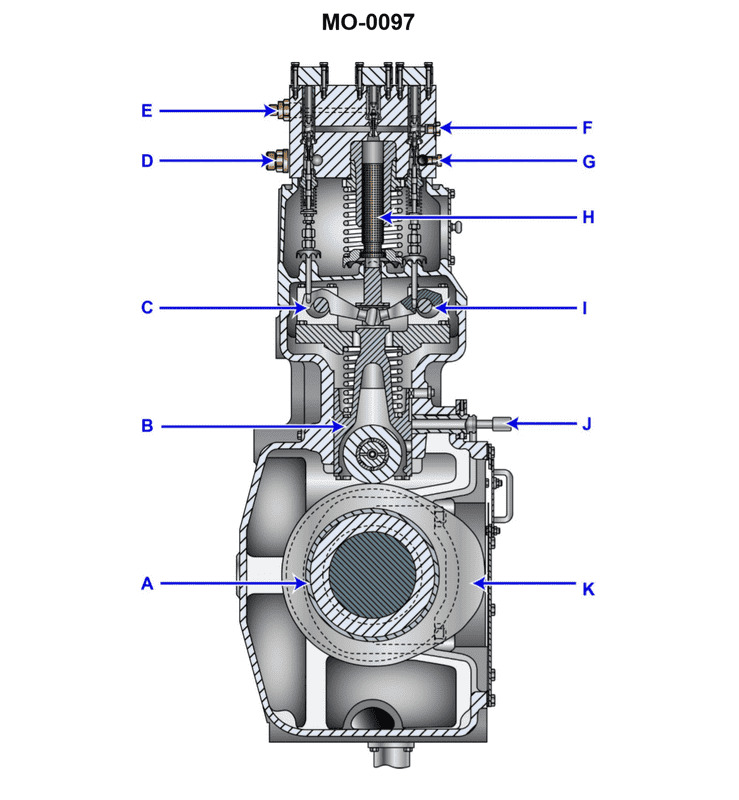
Question: The component shown in the illustration would be identified as a MO-0097
A. slow speed engine cylinder liner lubricator
B. centrifugal flyweight governor
C. slow speed engine fuel pump
D. injector cooling system pump
The correct answer is C) slow speed engine fuel pump. The MO-0097 component is a slow speed engine fuel pump, which is responsible for delivering fuel from the fuel tank to the engine's fuel injection system. This type of pump is a critical component in the operation of a slow speed marine diesel engine, ensuring a consistent and reliable supply of fuel to the engine. The other answer choices are incorrect because: A) A slow speed engine cylinder liner lubricator is a different component that provides lubrication to the engine's cylinder liners. B) A centrifugal flyweight governor is a mechanism that controls the engine's speed, not a fuel pump. D) An injector cooling system pump is used to circulate coolant to the engine's fuel injectors, not to deliver fuel.
Question 123
Question: The component identified as item #15 is used to _______________. Illustration MO-0016
A. test injector popping pressure
B. advance fuel pump timing
C. stop fuel delivery to the injector
D. increase the fuel pump delivery pressure
The correct answer is C) stop fuel delivery to the injector. The component identified as item #15 in the illustration MO-0016 is likely a fuel injector solenoid or valve, which is used to control the fuel delivery to the injector. This component is responsible for opening and closing the fuel supply to the injector, effectively stopping the fuel delivery when the solenoid or valve is closed. The other answer choices are incorrect because they do not accurately describe the function of this specific component. Choices A and D are related to the fuel pump, not the fuel injector, while choice B is about adjusting the fuel pump timing, which is a different system.
Question 124
Question: According to the illustration, initial timing of fuel injection into the cylinder is controlled with the component that is identified as the letter_______________. Illustration MO-0097
A. C
B. H
C. I
D. K
The correct answer is A. The timing of fuel injection into the cylinder is controlled by the fuel injection pump, which is identified as component C in the illustration MO-0097. The fuel injection pump is responsible for delivering the correct amount of fuel at the appropriate timing to the engine's cylinders, which is a critical factor in efficient engine operation. The other answer choices (H, I, and K) do not control the timing of fuel injection. They represent other engine components such as the flywheel, ignition coil, and governor, which have different functions in the engine's operation.
Question 125
Question: According to the illustration, fuel cutoff timing in the cylinder is controlled with the component that is identified as the letter_______________. Illustration MO-0097
A. C
B. H
C. I
D. K
The correct answer is C) I. The fuel cutoff timing in the cylinder is controlled by the fuel injection timing mechanism, which is identified by the letter "I" in the illustration MO-0097. This is the component that determines when the fuel is injected into the cylinder, and thus controls the timing of the fuel cutoff. The other options are incorrect because they do not directly control the fuel cutoff timing. Option A) C is likely the cylinder, option B) H could be the exhaust valve, and option D) K may be the crankshaft or camshaft, but none of these components directly control the fuel injection timing.
Question 126
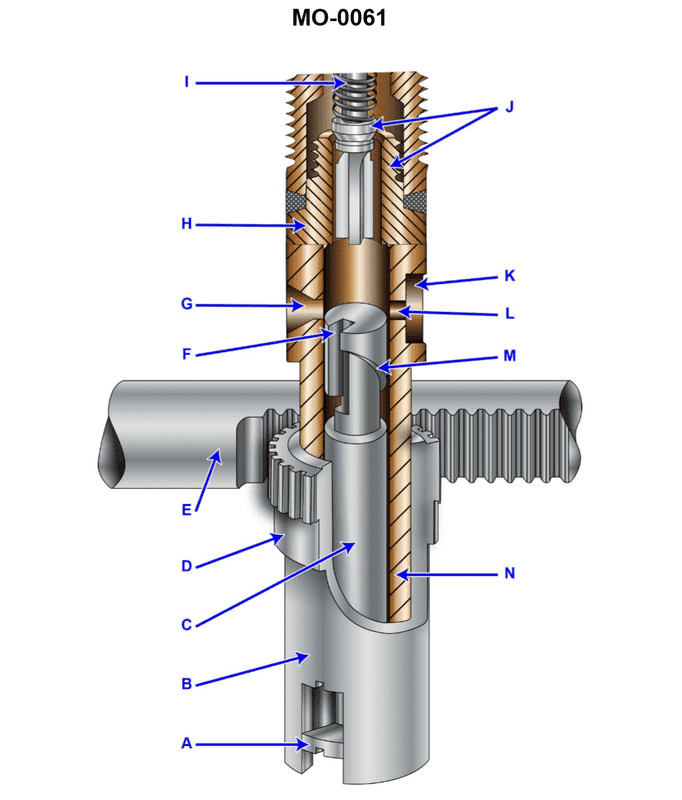
Question: As shown in the illustration of the fuel injection pump, the component labeled "N" would be identified as the_______________. Illustration MO-0061
A. Barrel
B. Sleeve
C. Control Rack
D. Plunger
The correct answer is A) Barrel. The barrel is the component labeled "N" in the illustration MO-0061 of the fuel injection pump. The barrel is the cylindrical housing that contains the plunger and controls the amount of fuel delivered to the engine cylinder. This is the key function of the barrel in a fuel injection pump system. The other options are incorrect because the sleeve is a different component, the control rack controls the movement of the plunger, and the plunger is a separate component from the barrel within the fuel injection pump.
Question 127
Question: As shown in the illustration of the fuel injection pump, the function of the area designated as "L" is to_______________. Illustration MO-0061
A. relieve excessive injector discharge pressure
B. control the fuel injection rate
C. allow excess fuel oil to return to the fuel oil system
D. provide for plunger lubrication
The correct answer is C) allow excess fuel oil to return to the fuel oil system. The area designated as "L" in the illustration is the fuel return line or the overflow line. Its function is to allow any excess fuel oil that is not injected into the engine cylinders to be returned to the fuel oil system. This helps maintain the proper pressure and flow of fuel to the injection pump. The other answer choices are incorrect because: A) does not describe the function of the specific area labeled "L", B) is a different function of the fuel injection pump, and D) is not the purpose of the area labeled "L".
Question 128
Question: In the illustration shown, moving the component labeled "E", further to the left, will result in_______________. Illustration MO-0061
A. a shorter fuel injection cycle
B. a greater quantity of fuel injected
C. an increase in the cylinder mean effective pressure
D. an increase in fuel pump delivery pressure
The correct answer is A) a shorter fuel injection cycle. Explanation: Moving the component labeled "E" (which is likely the fuel injection timing mechanism) further to the left would advance the timing of the fuel injection. This would result in the fuel being injected earlier in the engine's cycle, leading to a shorter overall fuel injection duration or cycle. The other answer choices are incorrect because they do not directly relate to the effect of advancing the fuel injection timing.
Question 129
Question: Which of the following statements represents the function of the plunger flange labeled "A" shown in the illustration? Illustration MO-0061
A. It prevents the plunger from rotating in the barrel.
B. It limits the actual stroke of the plunger.
C. It takes the plunger off stroke when injection is completed.
D. It transmits the control rack setting to the plunger.
The correct answer is D) It transmits the control rack setting to the plunger. The plunger flange labeled "A" in the illustration MO-0061 functions to transmit the control rack setting to the plunger. This allows the plunger to adjust its position and timing based on the control rack setting, which is a critical component in the fuel injection process. The other options are incorrect because: A) The plunger is prevented from rotating by other components, not the flange. B) The stroke of the plunger is limited by the design of the fuel injection pump, not the flange. C) The plunger is taken off stroke by the action of the control rack, not the flange.
Question 132
Question: Which type of diesel engine fuel nozzle is shown in the illustration? Illustration MO-0059
A. Open
B. Pintle
C. Self-cleaning
D. Multi-hole
The correct answer is D) Multi-hole. The illustration MO-0059 depicts a multi-hole diesel engine fuel nozzle, which is the typical design used in diesel engines. Multi-hole nozzles are characterized by having multiple small holes or orifices through which the fuel is sprayed into the engine cylinder, allowing for better atomization and more efficient combustion compared to other nozzle types. The other answer choices are incorrect because: A) Open nozzles are used in older diesel engines and have a single, larger hole; B) Pintle nozzles have a needle-like pintle that controls the fuel flow; and C) Self-cleaning nozzles have a mechanism to prevent clogging, which is not the primary feature shown in the illustration.
Question 133
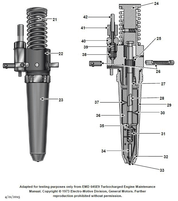
Question: Regarding the fuel injector shown in the illustration, the purpose of piece #38 is to_______________. Illustration MO-0059
A. filter the fuel
B. adjust the fuel rack spring tension
C. maintain fuel pressure at a preset level
D. relieve excess fuel pressure to the suction side of the pump
The correct answer is A) filter the fuel. The purpose of piece #38 in the fuel injector illustration MO-0059 is to filter the fuel. Fuel filters are essential components in fuel injection systems, as they remove contaminants and impurities from the fuel before it enters the injectors. This helps prevent damage to the delicate fuel system components and ensures the engine receives clean fuel for efficient combustion. The other answer choices are incorrect because piece #38 does not adjust the fuel rack spring tension (B), maintain fuel pressure at a preset level (C), or relieve excess fuel pressure to the suction side of the pump (D). Those functions are typically performed by other components in the fuel injection system.

Question 136
Question: The item labeled #16 in the illustration is a stack of spring washers. Their function is to_______________. Illustration MO-0062
A. permit accurate stretch gauge measurement of bolt elongation during installation
B. maintain the same hold-down force on the injector regardless of varying engine operating temperatures
C. prevent bolt failure by allowing limited movement of the injector when excessively high cylinder pressures are developed
D. absorb the high-pressure pulses developed during the fuel injection process
The correct answer is B) maintain the same hold-down force on the injector regardless of varying engine operating temperatures. Spring washers are used in fuel injection systems to compensate for changes in the hold-down force on the injector due to varying engine temperatures. As the engine heats up, the metal components expand, which can reduce the clamping force on the injector. The spring washers allow for some movement to maintain the proper hold-down force, ensuring consistent fuel delivery. The other answer choices are incorrect because they do not accurately describe the primary function of spring washers in a fuel injection system. They are not related to measuring bolt elongation, absorbing high-pressure pulses, or preventing bolt failure under high cylinder pressures.
Question 153
Question: The diesel engine shown in the illustration, is provided with an auxiliary blower to_______________. Illustration MO-0003
A. maintain a positive pressure on the crankcase
B. increase scavenge air pressure at full load
C. maintain a vacuum on the crankcase
D. provide scavenge air pressure at low load
The correct answer is D) provide scavenge air pressure at low load. The diesel engine shown in the illustration is equipped with an auxiliary blower, which is used to provide scavenge air pressure at low load conditions. At low engine loads, the engine's turbocharger may not be able to generate sufficient scavenge air pressure on its own. The auxiliary blower supplements the turbocharger's output to ensure adequate air supply to the engine under these conditions, maintaining proper combustion and engine performance. The other answer choices are incorrect because: A) maintaining positive crankcase pressure is not the purpose of the auxiliary blower, B) increasing scavenge air pressure at full load is the function of the turbocharger, not the auxiliary blower, and C) maintaining a vacuum on the crankcase is not the role of the auxiliary blower in this system.
Question 160
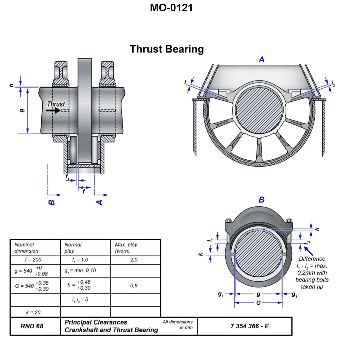
Question: When installing the bearing cap on the device shown in the illustration, which of the precautions listed must be observed? Illustration MO-0121
A. Prior to installing the cap, position the thrust shoes in their proper locations.
B. If the device is covered with abrasive material or contaminates, the unit may be reassembled, provided an abnormal method of reassembly is followed.
C. After applying anti-seize to the external threads, torque one side at a time to the appropriate values using a quality torque wrench.
D. Once the bearing cap is properly torqued, measure the end gap dimensions to ascertain even tightening of the cap.
The correct answer is D) Once the bearing cap is properly torqued, measure the end gap dimensions to ascertain even tightening of the cap. This is the correct answer because it is important to verify that the bearing cap has been evenly tightened to the appropriate torque specification. Measuring the end gap dimensions allows you to confirm that the cap has been installed correctly and will properly support the bearings. The other options are incorrect because: A) Positioning the thrust shoes is not directly related to installing the bearing cap; B) Reassembling a contaminated unit would not be a proper precaution; and C) Torquing one side at a time is not necessary, as the cap should be tightened evenly all the way around.
Question 161
Question: What is the maximum allowable clearance permitted between the bearing, shown in the illustration and the shaft along its vertical axis? Illustration MO-0121
A. 0.30 mm
B. 0.46 mm
C. 0.80 mm
D. 1.00 mm
The correct answer is C) 0.80 mm. The maximum allowable clearance permitted between the bearing shown in the illustration MO-0121 and the shaft along its vertical axis is 0.80 mm. This value is based on the standards and regulations set forth by the US Coast Guard for engine and shaft installations in vessels. The other options are incorrect because 0.30 mm (A) is too tight of a clearance, 0.46 mm (B) is also on the tighter side, and 1.00 mm (D) is too loose and would exceed the recommended maximum clearance. The 0.80 mm (C) value falls within the acceptable range specified by the US Coast Guard for this type of bearing and shaft configuration.
Question 162
Question: What is the normal bearing clearance permitted at the horizontal axis of the shaft for the bearing shown in the illustration? Illustration MO-0121
A. The tolerances established are dependent on machining processes used and will vary amongst manufacturers.
B. The normal play on both sides of the shaft will be one tenth of a millimeter.
C. The clearance on one side of the shaft at the axis will be one twentieth of a millimeter.
D. The clearance is determined by the thickness of the hydrodynamic wedge formed and is not usually measured while underway.
The correct answer is B) The normal play on both sides of the shaft will be one tenth of a millimeter. This is the correct answer because the typical clearance between the shaft and the bearing housing in a marine engine application is around 0.1 mm on each side. This small clearance allows for thermal expansion and prevents excessive wear while maintaining a stable hydrodynamic oil film. The tolerances are standardized across manufacturers and established through engineering best practices for marine machinery. The other options are incorrect because A) the tolerances are typically standardized, C) the clearance is on both sides, not just one, and D) the clearance is measured during installation, not just while underway.
Question 163
Question: After following the prescribed procedures to measure the thrust bearing clearance shown in the illustration, the distance "F" is determined to be 200 mm, and 'f1' is 2.3 mm. Which of the following statements describes the condition indicated by these dimensions? Illustration MO-0121
A. The loading ratio, or shaft diameter divided by collar surface area is within 2.7:1.
B. These dimensions indicate the presence of flourishing marks on the thrust shoes; the marks becoming visible as the distance at 'f1' increases.
C. It is possible for the shaft to move axially 2.3 mm during astern operation and relates to an excess movement of 1.3 mm, 0.3 mm beyond the maximum worn play.
D. The total active thrust area is 202.3 mm, well within the standards set forth by the GSMA (German Society for Machining Accuracy).
The correct answer is C. These dimensions indicate that the shaft can move axially 2.3 mm during astern operation, which relates to an excess movement of 1.3 mm, 0.3 mm beyond the maximum worn play. This is the correct interpretation because the maximum recommended axial play for a thrust bearing is typically 2.0 mm, and the measured play of 2.3 mm exceeds this limit, indicating potential issues with the thrust bearing. The other answer choices are incorrect because: A) the loading ratio is not mentioned in the problem; B) the flourishing marks are not a relevant factor in this scenario; and D) the total active thrust area is not a key measurement in determining the condition of the thrust bearing.
Question 166
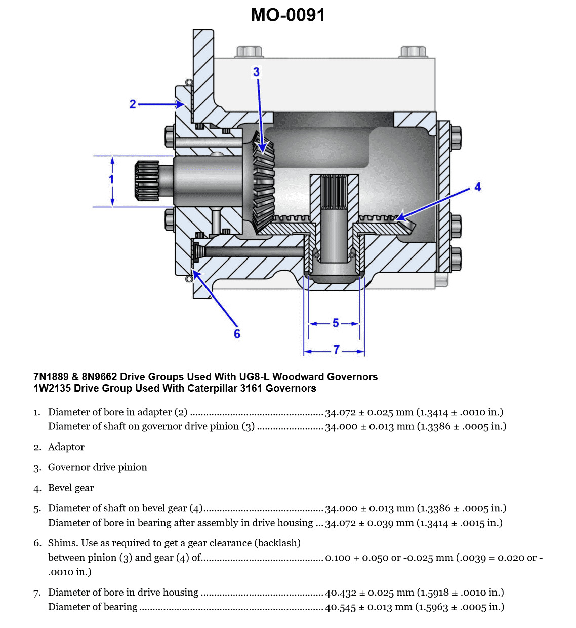
Question: The gear drive, shown in the illustration, can have the backlash determined best by using a_______________. Illustration MO-0091
A. lead wire
B. red dye indicator
C. feeler gauge
D. lash indicator
The correct answer is C) feeler gauge. A feeler gauge is the best tool to determine the backlash in a gear drive. Backlash is the amount of clearance or play between the mating gear teeth, and a feeler gauge can precisely measure this clearance. Using a feeler gauge allows you to insert the appropriate thickness of the gauge between the gear teeth and accurately assess the amount of backlash present. The other options are not as suitable for measuring backlash. A lead wire or dye indicator would not provide a precise measurement, and a lash indicator is typically used to measure the wear or looseness in a mechanical linkage, not a gear drive.
Question 167
Question: The thrust bearing shown in the illustration has over eight years of ahead running time. Measurements show "i1" is 4 mm and "i2" is 1mm. Which of the following conditions is indicated and what steps should be taken, if any? Illustration MO-0121
A. The stops in which the thrust bearing block rides are worn, and it is necessary to return these to their original specifications.
B. No appreciable wear has occurred, and the proper maintenance procedures should continue to be followed.
C. A wear rate of 1.6 mm per year is excessive and requires immediate assistance from the manufacturer's field support.
D. A wear rate of 1.6 mm per year occurred. Although not excessive, this condition may require more frequent monitoring.
The correct answer is B) No appreciable wear has occurred, and the proper maintenance procedures should continue to be followed. The reasoning is that the illustration shows a thrust bearing with over 8 years of ahead running time, and the measurements indicate a small difference between "i1" (4 mm) and "i2" (1 mm), which suggests minimal wear. A wear rate of 1.6 mm per year (as indicated in option C) would be considered excessive for a thrust bearing with this much operating time. Therefore, option B is the correct answer, as the thrust bearing does not show signs of significant wear and the proper maintenance procedures should be continued. The other options are incorrect because option A incorrectly suggests the stops are worn, when the measurements indicate minimal wear on the thrust bearing itself. Option C proposes an excessive wear rate that is not supported by the information provided, and option D suggests a need for more frequent monitoring, which is not necessary based on the low wear rate indicated by the measurements.
Question 174
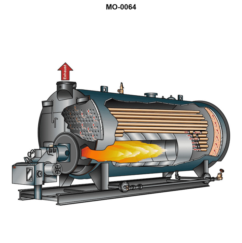
Question: The boiler shown in the illustration would be classed as MO-0064
A. single-pass, fire-tube, scotch marine
B. forced circulation, coil-type
C. two-pass, scotch marine
D. two-pass, water-tube
The correct answer is A) single-pass, fire-tube, scotch marine. The illustration provided depicts a single-pass, fire-tube, scotch marine boiler. This type of boiler is commonly used on smaller vessels, including those operated by the US Coast Guard. The fire-tube design and single-pass configuration are the key features that identify this boiler as a scotch marine type, which makes option A the correct choice. The other options are incorrect because they describe different boiler types that do not match the illustration. Option B describes a forced circulation, coil-type boiler, option C describes a two-pass, scotch marine boiler, and option D describes a two-pass, water-tube boiler, none of which match the characteristics of the boiler shown.
Question 184
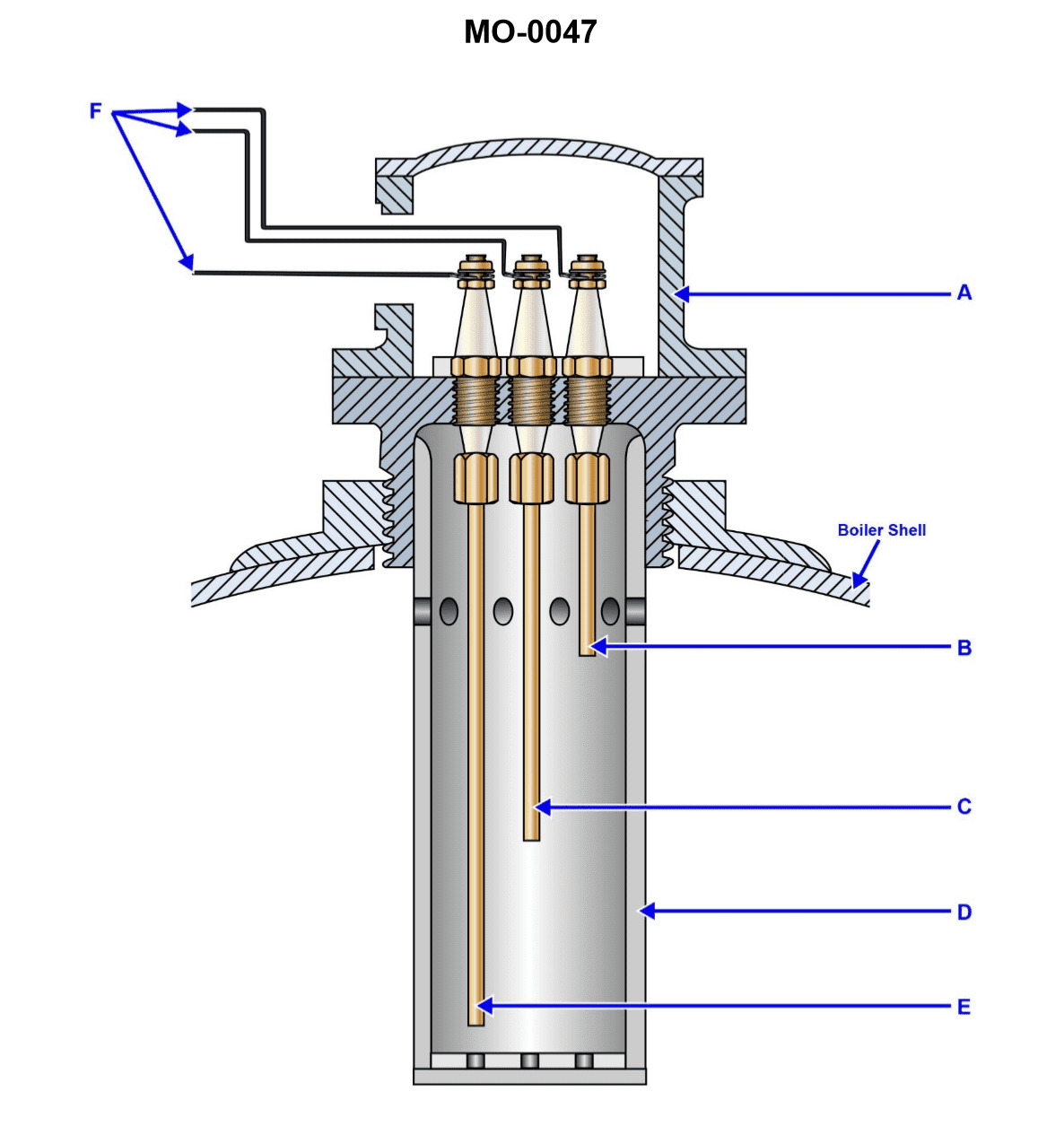
Question: In the water level electrode assembly, shown in the illustration, the feed pump should restart when the level of the water reaches the position indicated by arrow '_____ '. Illustration MO-0047
A. E
B. B
C. C
D. D
The correct answer is C. The feed pump should restart when the water level reaches the position indicated by arrow C. This is because the water level electrode assembly is designed to control the feed pump operation based on the water level. When the water level drops to the position indicated by arrow C, the electrode will detect this and signal the feed pump to restart in order to refill the tank. The other options are incorrect because they do not correspond to the position where the feed pump should restart. Option A (E) is too low, option B (B) is too high, and option D (D) is also not the correct position for the feed pump to restart.
Question 194
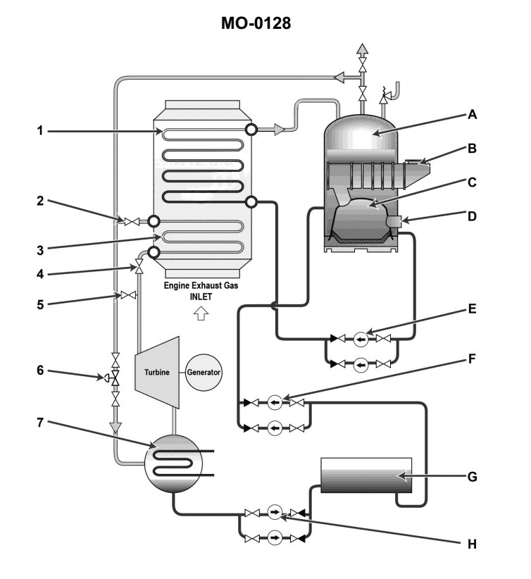
Question: As shown in the illustration, the component labeled "H" would be identified as a_______________. Illustration MO-0128
A. waste heat boiler circulating pump
B. fuel oil service pump
C. main condensate pump
D. boiler water feed pump
The correct answer is C) main condensate pump. The main condensate pump is responsible for circulating the condensed steam from the main condenser back to the boiler. This is a crucial component in the steam propulsion system, as it ensures the continuous recycling of the condensed steam to maintain the boiler's water level and overall efficiency. The other options are incorrect because: A) a waste heat boiler circulating pump is used to circulate the water in a waste heat boiler, B) a fuel oil service pump is used to supply fuel oil to the burners, and D) a boiler water feed pump is used to supply water to the boiler, which is a different function from the main condensate pump.
Question 195
Question: As shown in the illustration, the component labeled 'E' would be identified as a_______________. Illustration MO-0128
A. waste heat boiler circulating pump
B. boiler water feed pump
C. main condensate pump
D. fuel oil service pump
The correct answer is A) waste heat boiler circulating pump. This is the correct answer because the component labeled 'E' in the illustration MO-0128 is responsible for circulating the heated water from the waste heat boiler, which is a common component in marine propulsion systems. The waste heat boiler uses the hot exhaust gases from the main engine to generate steam or hot water, and the circulating pump ensures proper circulation of this heated fluid. The other answer choices, such as a boiler water feed pump, main condensate pump, or fuel oil service pump, do not match the function described by the 'E' label in the given illustration.
Question 197
Question: As shown in the illustration, the function of component "1" is to_______________. Illustration MO-0128
A. generate superheated steam to operate the turbo generator
B. evaporate circulating boiler water into saturated steam
C. condense excess steam produced in the boiler
D. maintain a water level in the steam drum
The correct answer is B) evaporate circulating boiler water into saturated steam. The function of component "1" in the illustration MO-0128 is to evaporate the circulating boiler water into saturated steam. This is a critical component in the steam generation process, as it converts the liquid water into the steam that will then power the machinery onboard the vessel. The other answer choices are incorrect because: A) generating superheated steam is a different process that occurs downstream of the boiler; C) condensing excess steam is a separate function handled by other components; and D) maintaining the water level in the steam drum is a different task, not the primary function of component "1".
Question 201
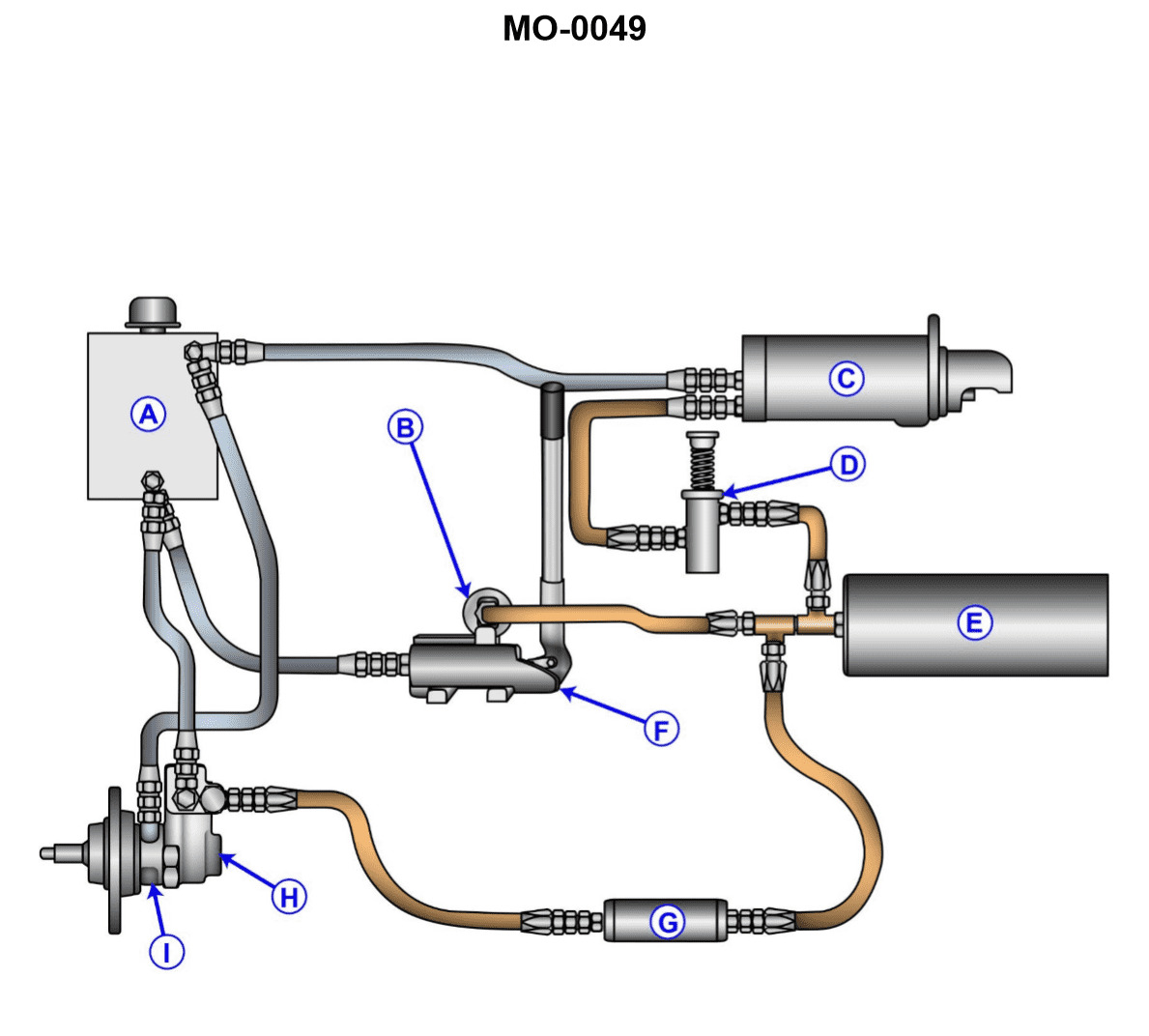
Question: The starter control valve in the hydraulic system shown in the illustration is malfunctioning. Before removing the valve, you must first_______________. Illustration MO-0049
A. drain the reservoir
B. remove all plugs from the system
C. bleed off all accumulator pressure in "E"
D. ensure that the accumulator piston is in the charged position
The correct answer is C) bleed off all accumulator pressure in "E". The reasoning for this is that before servicing or removing a component in a hydraulic system, it is essential to relieve any residual pressure in the system. In this case, the starter control valve is malfunctioning, and bleeding off the accumulator pressure is a necessary step before removing the valve. This is to prevent any sudden release of pressurized fluid, which could be hazardous. The other options are incorrect because draining the reservoir (A) or removing all plugs (B) are not necessary steps before servicing the starter control valve. Ensuring the accumulator piston is in the charged position (D) is also not relevant to the task at hand, which is to safely remove the malfunctioning valve.
Question 220
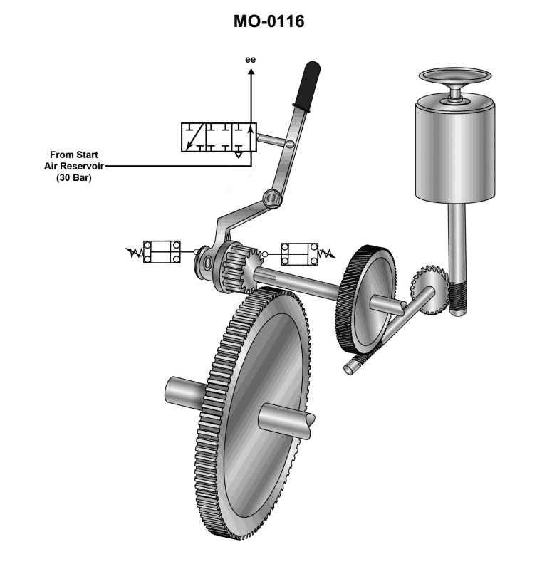
Question: What device is installed and used as a safety feature to satisfy Coast Guard regulations for the unit shown in the illustration? Illustration MO-0116
A. Spring clutch
B. Overrunning clutch
C. Pneumatic three position valve
D. Electrical limit switch
The correct answer is D) Electrical limit switch. An electrical limit switch is typically used as a safety feature to satisfy Coast Guard regulations for the unit shown in the illustration MO-0116. Limit switches are designed to automatically cut off or limit the operation of machinery when it reaches a certain predetermined position or point, preventing potential accidents or damage. This helps ensure the safe operation of the equipment and compliance with Coast Guard safety standards. The other options, such as a spring clutch, overrunning clutch, or pneumatic three-position valve, would not be the primary safety feature required by Coast Guard regulations for this specific illustration.
Question 223
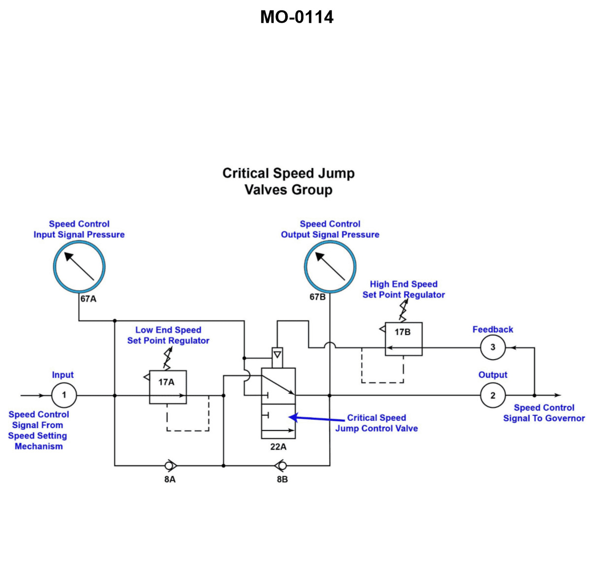
Question: A propulsion engine, using the speed control circuit shown in the illustration, fails to function at speeds lower than the low end of the critical speed range. Which of the following statements describes what should be done to correct this malfunction? Illustration MO-0114
A. To increase the critical speed range of the engine, reduce the setpoint of 17A and 17B respectively, to 0.80 bar and 1.0 bar.
B. Device 17A needs to be replaced, repaired, or reset to the setpoint coinciding with the RPM value for the low end of the critical speed range.
C. The critical speed range will be varied as the setpoints of 17A or 17B are reset, therefore, another segment of the speed control circuit must be repaired.
D. Both 17A and 17B need to be reset to decrease the critical speed range, although this procedure will increase the operating range of the engine.
The correct answer is B. Device 17A needs to be replaced, repaired, or reset to the setpoint coinciding with the RPM value for the low end of the critical speed range. The reasoning is that if the propulsion engine fails to function at speeds lower than the low end of the critical speed range, the issue is likely with the setpoint of device 17A, which is responsible for maintaining the engine's critical speed range. Resetting or repairing 17A to the appropriate setpoint should correct the malfunction and allow the engine to function properly at lower speeds. The other options are incorrect because reducing the setpoints of 17A and 17B (option A) would not address the specific issue of the engine not functioning at lower speeds, and resetting both 17A and 17B (option D) would alter the critical speed range rather than addressing the root cause. Option C is incorrect because the critical speed range should not need to be varied to correct this specific malfunction.
Question 224
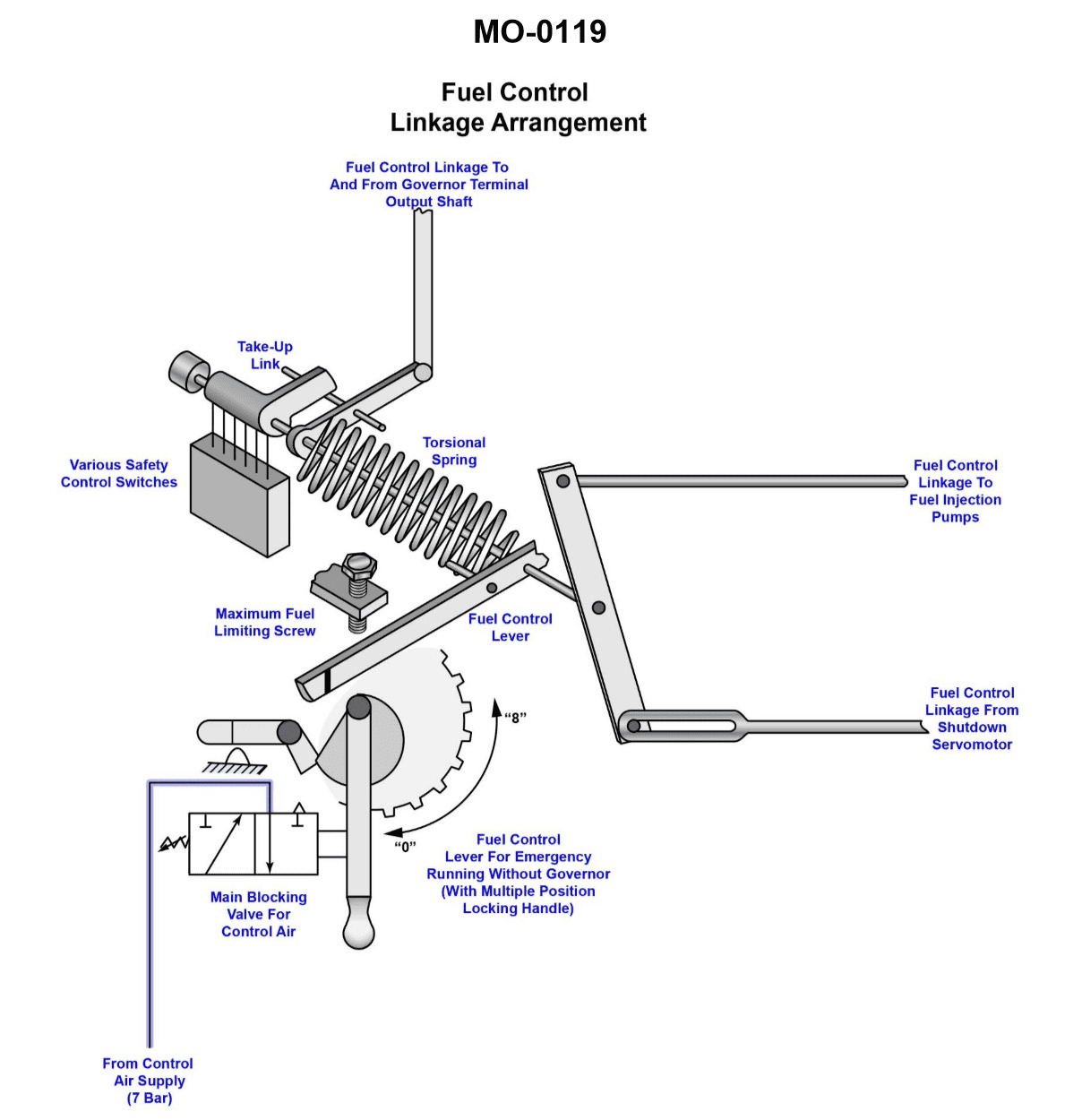
Question: The governor utilized with the device shown in the illustration has become inoperative while the vessel is underway at sea. Which of the following statements describes what action should be taken? Illustration MO-0119
A. The linkage to the shut down servomotor and the governor output shaft must be disconnected in order to operate the engine via the fuel control lever.
B. The engine speed can be controlled using the fuel control lever without changing the position of the maximum fuel stop.
C. It is necessary to disconnect the shuttle valve from the throttle lever horizontal bar, in order to effectively jump out the pneumatic engine enable control circuit.
D. The governor should be replaced with one that has been proven to be useful in isochronous applications.
The correct answer is B) The engine speed can be controlled using the fuel control lever without changing the position of the maximum fuel stop. This is the correct answer because when the governor becomes inoperative, the engine can still be controlled manually using the fuel control lever. The maximum fuel stop setting does not need to be changed, as the governor is no longer controlling the engine speed. The fuel control lever can be used to adjust the engine speed as needed. The other options are incorrect because they suggest unnecessary actions, such as disconnecting the linkage or the shuttle valve, which are not required when the governor becomes inoperative. Additionally, replacing the governor with one designed for isochronous applications is not the appropriate action in this scenario, as the focus should be on maintaining control of the engine using the available manual controls.
Question 226
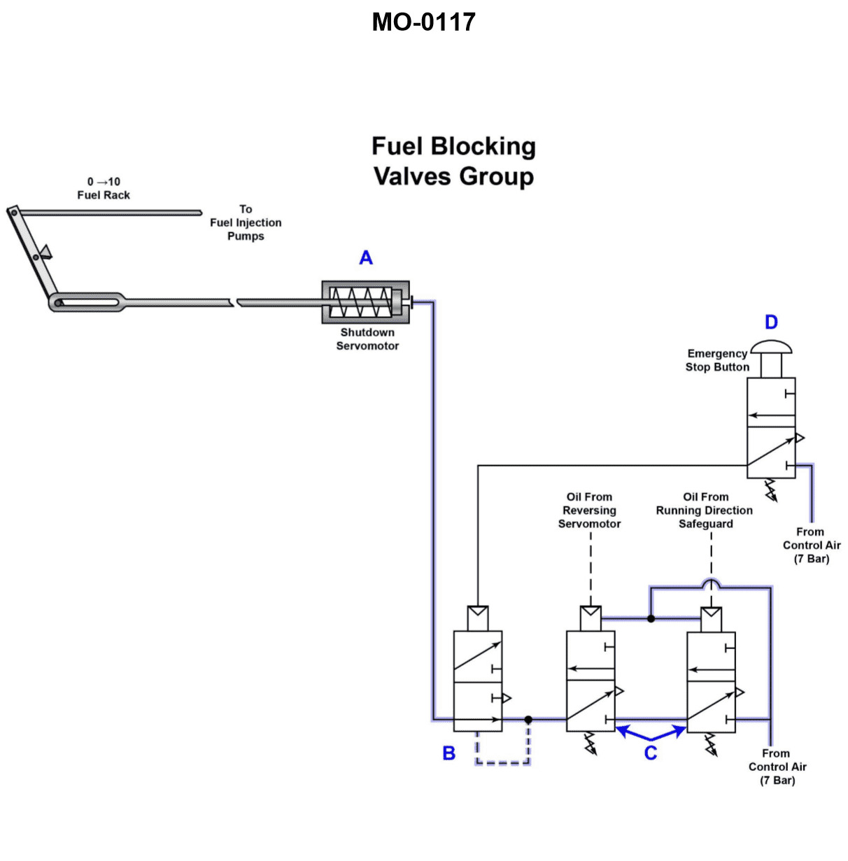
Question: The pneumatic circuit shown in the illustration is part of a complex large low-speed engine control system. Which of the following statements describes the function of this circuit? Illustration MO-0117
A. The circuit shown is used to shift the camshaft position when reversing the engine.
B. The piston labeled A provides a low-pressure signal to the other components illustrated.
C. Valve D, when depressed, allows the retained pneumatic pressure within the shutdown servomotor to be relieved.
D. When oil pressure to valve C is diminished, a pressure decrease is developed at valve D, causing it to shift, and nullifying the actuating signal to device A.
The correct answer is C) Valve D, when depressed, allows the retained pneumatic pressure within the shutdown servomotor to be relieved. This is correct because the pneumatic circuit shown is likely part of an engine shutdown or emergency control system. Valve D is likely a manual override valve that, when depressed, releases the pneumatic pressure in the shutdown servomotor, allowing the engine to be restarted or the system to be reset. The other answer choices are incorrect because they do not accurately describe the function of this specific pneumatic circuit. The circuit is not used for camshaft position adjustment (A), the piston labeled A is not providing a low-pressure signal (B), and the circuit is not designed to nullify an actuating signal due to diminished oil pressure (D).
Question 227
Question: If the input signal rises above the setpoint of '17A', shown in the illustration, but remains below the setpoint of '17B', the output from '22A' will_______________. Illustration MO-0114
A. indicate a pressure on '67B' equal to the setpoint of '17A'
B. be the same as the setpoint of '17B'
C. indicate a pressure on '67A' equal to the input of '17A'
D. improve to a steady state when moisture is removed from the system
The correct answer is A) indicate a pressure on '67B' equal to the setpoint of '17A'. When the input signal rises above the setpoint of '17A' but remains below the setpoint of '17B', the system is operating in the range between the two setpoints. In this case, the output from '22A' will indicate a pressure on '67B' that is equal to the setpoint of '17A', as this is the pressure that triggers the system's response. The other answer choices are incorrect because: B) the output would not be the same as the setpoint of '17B' since the input has not reached that level; C) the output would not indicate the pressure on '17A' itself, but rather the pressure it triggers on '67B'; and D) improving to a steady state due to moisture removal is not relevant to the specific scenario described.
Question 228
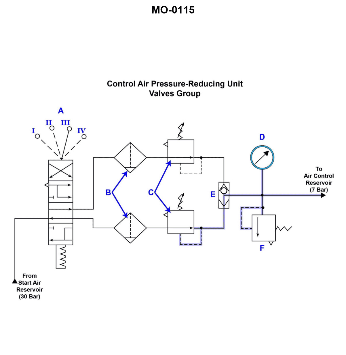
Question: The circuit shown in the illustration represents a/an_______________. MO- 0115
A. infinitely positioned pneumatic control
B. detented, control air pressure, reducing and filtering unit
C. pneumatic actuated, multiple position, control unit
D. hydraulic actuated, multi-position control unit
The correct answer is B) detented, control air pressure, reducing and filtering unit. This is the correct answer because the circuit shown in the illustration represents a pneumatic control unit that reduces and filters the control air pressure, and has multiple detented positions to allow for precise control. This type of unit is commonly used in marine applications, such as with the US Coast Guard, to manage and regulate the airflow in various onboard systems. The other answer choices are incorrect because they do not accurately describe the specific type of pneumatic control unit represented in the illustration. Options A, C, and D describe different types of pneumatic or hydraulic control units that do not match the characteristics of the circuit shown.
Question 229
Question: Which of the following statements describes the function of the device labeled "C" shown in the illustration? Illustration MO-0115
A. The device is a relief valve with feedback to prevent excessive pressure from damaging system components.
B. The regulator, or pressure reducer, drops the supply pressure to the desired operating level.
C. The regulator reduces the pressure of the supply air to provide ancillary main engine services.
D. Constant pressure is maintained at device "B" while device "C" is used only to modify the output signal.
The correct answer is B) The regulator, or pressure reducer, drops the supply pressure to the desired operating level. This is the correct answer because the function of the device labeled "C" in the illustration is to reduce the pressure of the supply air to provide the appropriate operating pressure for the ancillary main engine services. The regulator is used to convert the higher supply pressure to a lower, more suitable pressure for the system's components. The other answer choices are incorrect because they do not accurately describe the primary function of the pressure-reducing device labeled "C" in the illustration. Option A describes a relief valve, option C is redundant with the correct answer, and option D does not align with the role of the regulator in the system.
Question 230
Question: What is the primary purpose of the pneumatic component shown in the illustration? Illustration MO-0119
A. If the locking handle is in any position other than 'zero', the output of the pneumatic valve will equal the input.
B. The indicated valve prevents transmission of transient signals to the governor speeder spring.
C. The valve with finite positioning is used to segregate terminal signals originated by the governor whenever the throttle is repositioned.
D. If the throttle is manually moved from its 'zero' position, the resulting effect will tend to override the output of the governor, and secure the air to the control circuit.
The correct answer is D: If the throttle is manually moved from its 'zero' position, the resulting effect will tend to override the output of the governor, and secure the air to the control circuit. This is correct because the primary purpose of the pneumatic component shown in the illustration is to prevent the governor from affecting the engine's operation when the throttle is manually moved. By securing the air to the control circuit, the valve overrides the governor's output and allows the operator to have direct control over the engine, which is essential for safe operation. The other options are incorrect because they do not accurately describe the primary function of this pneumatic component. Option A discusses the valve's behavior in different positions, option B mentions transient signal transmission, and option C talks about segregating terminal signals, none of which are the main purpose of this valve.
Question 241
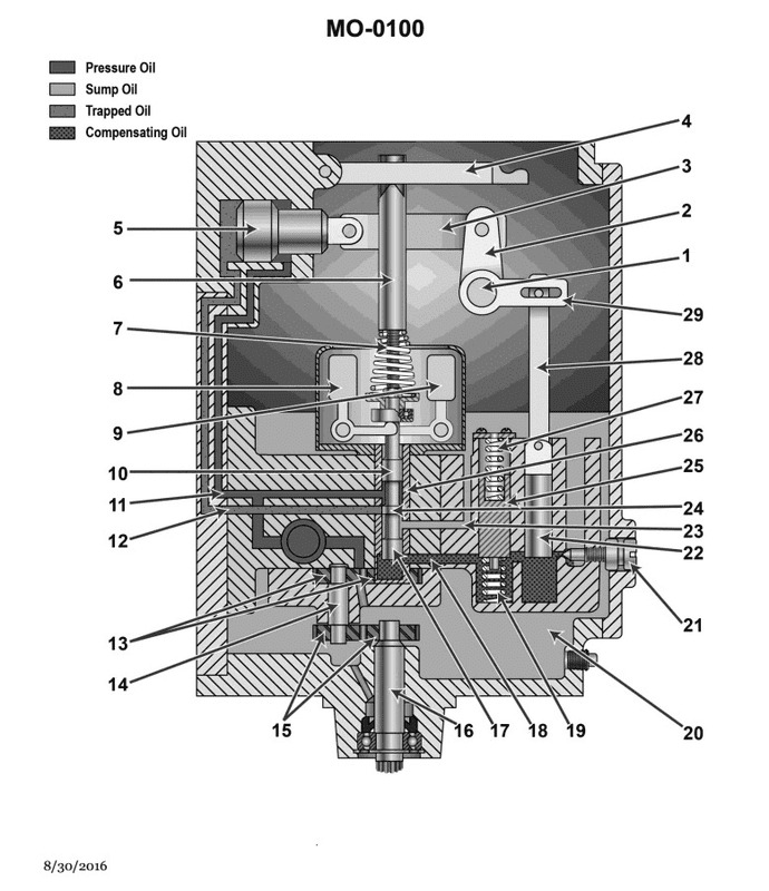
Question: A schematic diagram of an isochronous hydraulic governor is shown in the illustration. When the load is removed the speed increases, and the_______________. Illustration MO-0100
A. balance piston (piece 22)
B. B
C. move inward and the pilot valve (piece 10
D. C
The correct answer is C) move inward and the pilot valve (piece 10). When the load is removed, the speed of the engine increases. In an isochronous hydraulic governor, this increased speed causes the balance piston (piece 22) to move inward, which in turn moves the pilot valve (piece 10) inward. This action adjusts the fuel supply to the engine, reducing the speed and maintaining a constant RPM. The other options are incorrect because the balance piston does not move outward (A), and the correct answer is specifically about the pilot valve moving inward (C), not just the general movement of components (B and D).
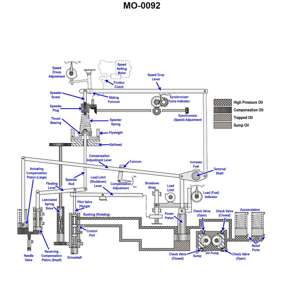
Question 242
Question: Increasing the oil pressure acting on the power piston of the hydraulic governor shown in the illustration will_______________. Illustration MO-0092
A. increase the governor output power
B. decrease the speed droop
C. require the overspeed trip setting to be adjusted
D. increase the speed droop
The correct answer is A) increase the governor output power. Increasing the oil pressure acting on the power piston of the hydraulic governor will increase the governor output power. This is because the power piston is responsible for generating the force that opposes the centrifugal force acting on the flyweights, which ultimately controls the governor's output power. By increasing the oil pressure on the power piston, you increase the force it can exert, leading to a higher governor output power. The other options are incorrect because: B) decreasing the speed droop is not a direct result of increasing the oil pressure; C) the overspeed trip setting does not need to be adjusted simply by changing the oil pressure; and D) increasing the oil pressure would actually decrease the speed droop, not increase it.
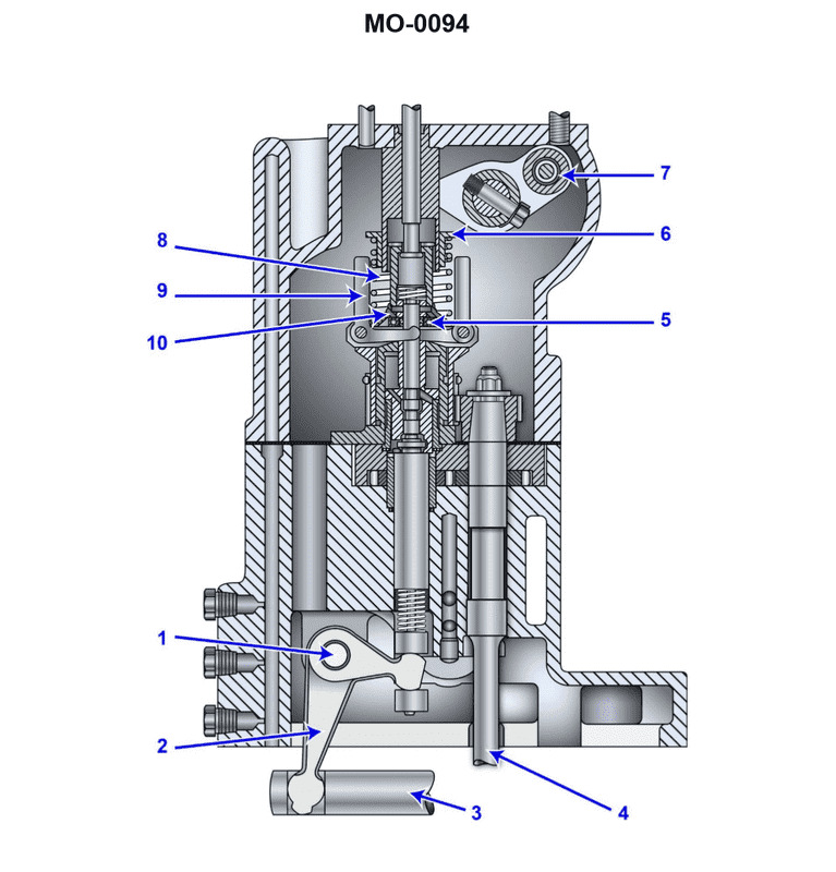
Question 244
Question: The governor for an emergency diesel generator is shown in the illustration. When a large change in load results in a change in engine speed, which of the parts listed will be the FIRST governor component to react to the change in load? Illustration MO-0094
A. Piece #8
B. Piece #9
C. Piece #13
D. Piece #21
The correct answer is B) Piece #9. The governor's flyball mechanism (piece #9) is the first component to react to a change in engine speed. When the engine speed changes due to a change in load, the flyball mechanism immediately senses this change and initiates the governor's response to bring the engine speed back to the desired setpoint. The other components, such as the control linkage (piece #8), the pilot valve (piece #13), and the hydraulic actuator (piece #21), are responsible for translating the flyball mechanism's input into an adjustment of the engine's fuel supply, but the flyball mechanism is the initial sensing element that triggers the governor's corrective action.
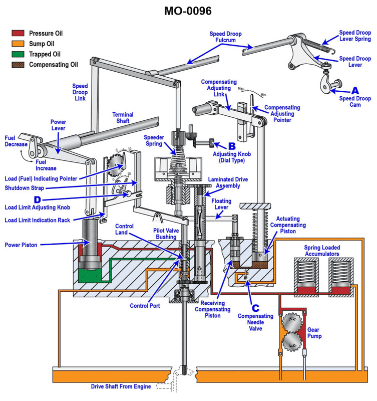
Question 245
Question: Which of the following statements is correct concerning the operating function of the governor shown in the illustration? Illustration MO-0096
A. Excess oil under high-pressure is released from the spring loaded accumulators to the sump.
B. The speed droop lever spring prevents the engine from racing or hunting by arresting the movement of the power piston after a speed change.
C. The dial type adjusting knob
D. is used for setting speed droop and damping out hunting.
The correct answer is D) The dial type adjusting knob is used for setting speed droop and damping out hunting. The governor's function is to maintain a constant engine speed despite changes in load. The dial type adjusting knob allows the operator to set the desired amount of speed droop, which is the intentional reduction in engine speed under load. This droop helps prevent the engine from racing or "hunting" when the load changes. The adjusting knob also controls the damping, which stabilizes the governor's response to changes in load and prevents oscillations. The other options are incorrect because they do not accurately describe the primary function of the governor's adjusting knob. Option A discusses the accumulators, which are not directly related to the adjusting knob's purpose. Option B incorrectly describes the role of the speed droop lever spring, which is a separate component from the adjusting knob.