Pass Your Coast Guard Licensing Exams!
Study offline, track your progress, and simulate real exams with the Coast Guard Exams app
Motor Plants - QMED
27 images
Question 6
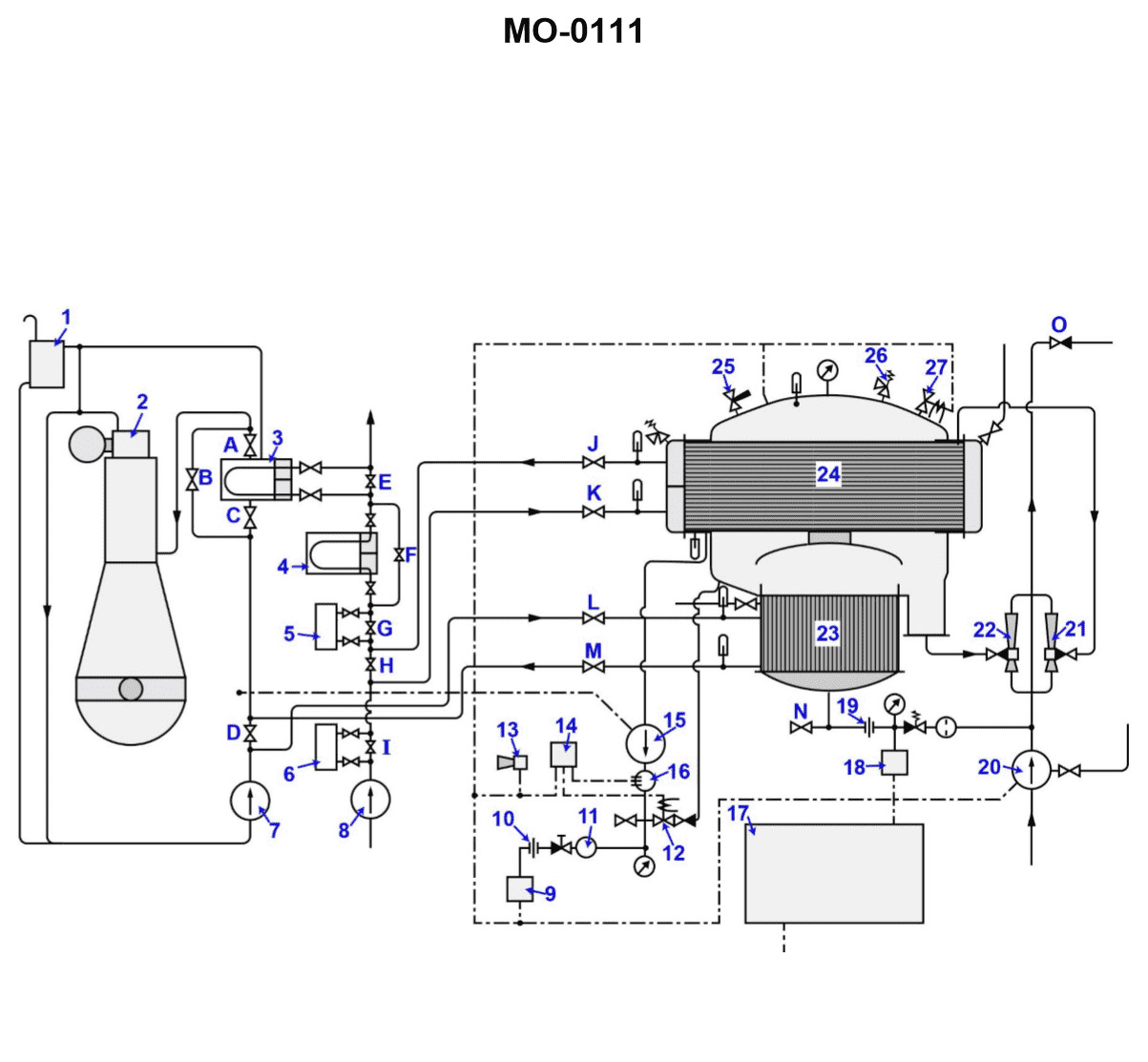
Question: According to the illustrated main engine cooling water systems drawing, which of the labeled heat exchangers represents the charge air coolers? Illustration MO-0111
A. 3 and 4
B. 4 and 5
C. 4 and 6
D. 5 and 6
The correct answer is D) 5 and 6. The charge air coolers are typically represented by the heat exchangers labeled 5 and 6 in the illustrated main engine cooling water systems drawing MO-0111. This is because the charge air coolers are responsible for cooling the intake air after it has been compressed by the turbocharger, before it enters the engine cylinders. The charge air coolers are a critical component of the engine cooling system, as they help improve engine efficiency and performance. The other answer choices are incorrect because they do not accurately identify the heat exchangers representing the charge air coolers in the given illustration.
Question 12
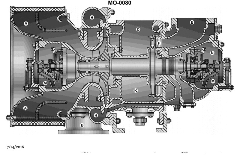
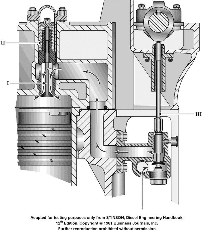
Question: The device shown in the illustration is commonly used to_______________. MO-0080
A. utilize the flow of exhaust gases to supercharge the engine
B. protect the crankcase from overpressure in event of explosion
C. provide cooling water circulation through the engine
D. provide air starting pressure
The correct answer is A) utilize the flow of exhaust gases to supercharge the engine. This device is commonly referred to as a turbocharger. Turbochargers use the flow of the engine's exhaust gases to drive a turbine, which in turn spins a compressor that forces more air into the engine's intake. This increases the density of the air-fuel mixture, allowing the engine to produce more power. This is a common technique used to supercharge engines and boost their performance. The other answer choices are incorrect because: B) is describing a crankcase ventilation system, C) is describing a water pump, and D) is describing an air start system, none of which are the function of a turbocharger.
Question 13
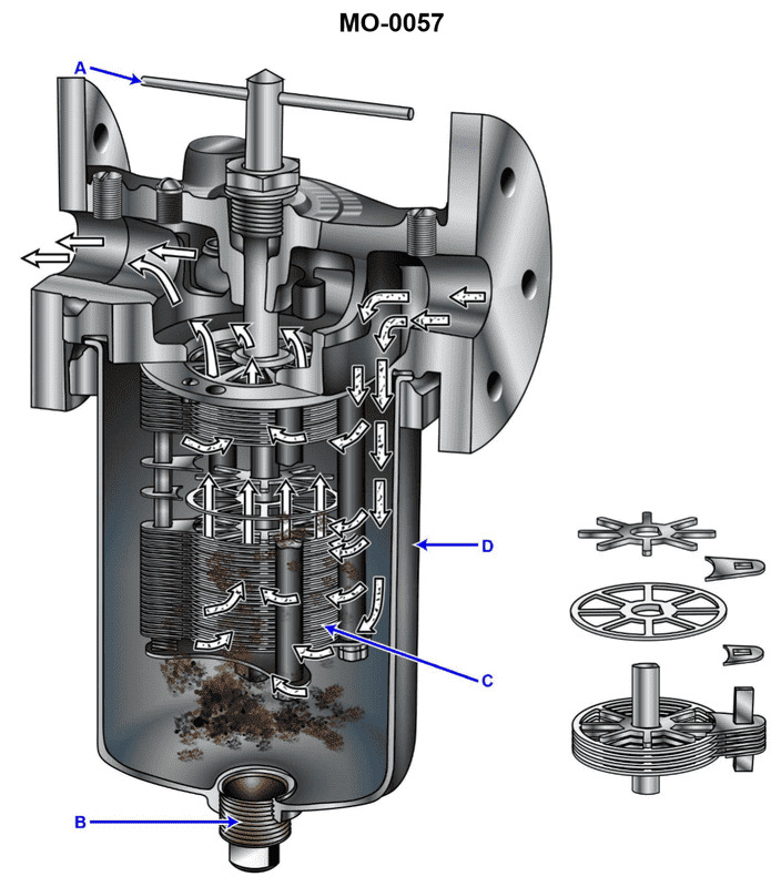
Question: How is the illustrated strainer element cleaned during engine operation? Illustration MO-0057
A. The T-handle is rotated
B. The housing is removed and the element is cleaned with a solvent.
C. The drain plug is removed and the housing is drained
D. The strainer element is removed, cleaned in kerosene or solvent, and dried with an air brush
The correct answer is A) The T-handle is rotated. During engine operation, the illustrated strainer element is cleaned by rotating the T-handle. This allows the strainer to be backflushed, clearing any debris or contaminants that have accumulated in the screen. This method of cleaning the strainer element is preferred during engine operation, as it can be done without disassembling the housing or removing the entire element. The other options are incorrect because they describe more involved cleaning methods that would typically be performed during scheduled maintenance, rather than during normal engine operation.
Question 38
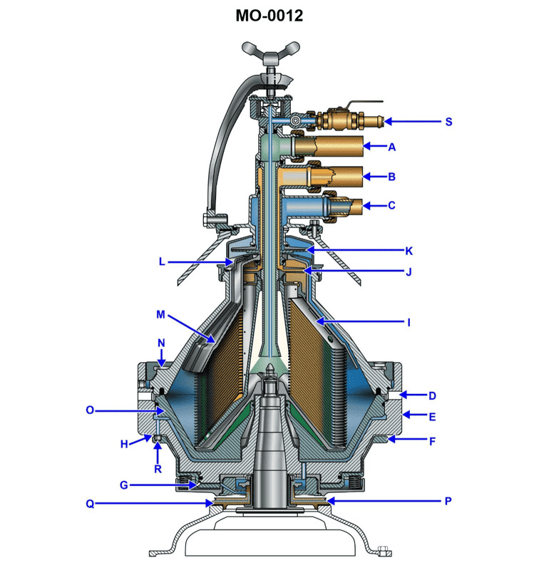
Question: A modern centrifuge, similar to the device shown in the illustration, is opened for periodic cleaning. The most common cause of operating failure after reassembling is due to _______________. Illustration MO-0012
A. low drive motor RPM
B. excessive back pressure in the bowl and fuel oil break over
C. the failure of the opening and closing water supply
D. not replacing the bowl O-rings that have taken a permanent set
The correct answer is D) not replacing the bowl O-rings that have taken a permanent set. The most common cause of operating failure after reassembling a modern centrifuge is due to the failure to replace the bowl O-rings that have taken a permanent set. Over time, the constant exposure to heat, pressure, and vibration can cause the O-rings to deform and lose their sealing ability. If the O-rings are not replaced during periodic maintenance, the centrifuge may experience leaks, uneven operation, or even a catastrophic failure when reassembled and put back into service. The other answer choices are not the most common causes of failure. Low drive motor RPM, excessive back pressure, and issues with the water supply are less likely to occur compared to the degradation of the critical O-ring seals.
Question 60
Question: During the starting of a diesel engine, compression gases are prevented from backing into the air starting system, shown in the illustration, by the__________. Illustration MO-0046
A. cylinder air starting check valves
B. high-pressure in the starting air manifold
C. air starting control valve
D. individual distribution valves
The correct answer is A) cylinder air starting check valves. The cylinder air starting check valves prevent compression gases from backing into the air starting system during the starting of a diesel engine. These check valves allow air to flow from the starting air manifold into the engine cylinders, but not in the reverse direction. This ensures that the high-pressure air is directed into the cylinders to start the engine, rather than allowing the compression gases to flow back into the air starting system. The other options are incorrect because: B) high-pressure in the starting air manifold does not directly prevent the backflow, C) the air starting control valve controls the supply of air to the engine, but does not prevent backflow, and D) individual distribution valves distribute the air to the cylinders, but do not specifically prevent backflow.
Question 67
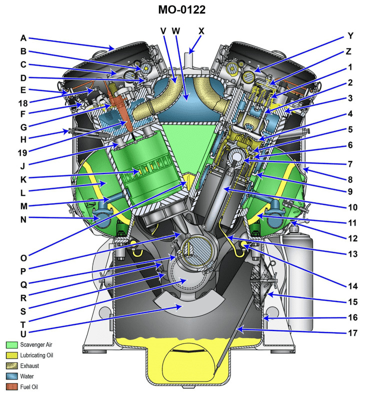
Question: The diesel engine wrist pin in the illustration is indicated by the component labeled_______________. Illustration MO-0122
A. "7"
B. "17"
C. "G"
D. "S"
The correct answer is A) "7". The wrist pin, also known as the piston pin, is the component that connects the piston to the connecting rod in a diesel engine. In the illustration MO-0122, the wrist pin is clearly labeled as component "7". The other answer choices are incorrect because: B) "17" refers to the gudgeon pin, which is a different component. C) "G" and D) "S" do not correspond to any labels in the provided illustration.
Question 75
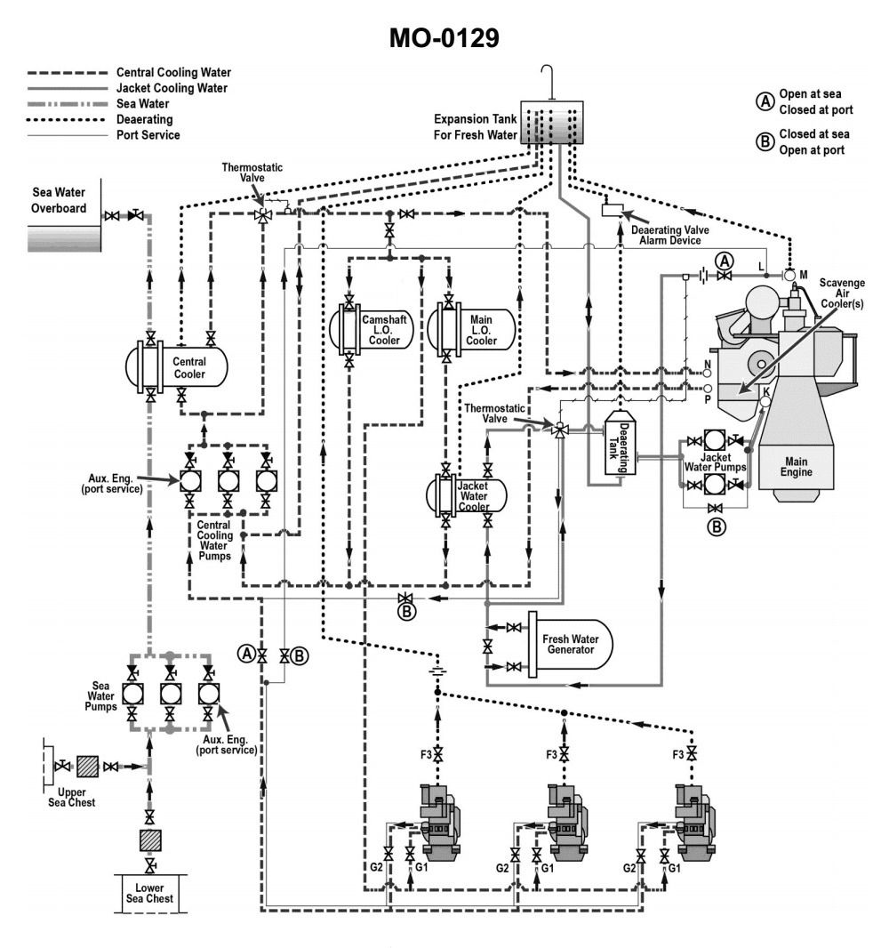
Question: According to the illustrated diesel engine cooling water systems diagram, what fluid is the low temperature central fresh water thermostat designed to maintain? Illustration MO-0129
A. The low temperature central fresh water return header temperature.
B. The low temperature central fresh water cooler outlet temperature.
C. The low temperature central fresh water supply header temperature.
D. The low temperature central fresh water cooler inlet temperature.
The correct answer is C) The low temperature central fresh water supply header temperature. The low temperature central fresh water thermostat is designed to maintain the temperature of the central fresh water supply header. This ensures that the cooling water being circulated through the engine is kept at the proper operating temperature, which is critical for efficient engine performance and protection. The other answer choices are incorrect because they do not accurately describe the function of the low temperature central fresh water thermostat. The thermostat is not designed to maintain the temperature of the central fresh water return header, the cooler outlet, or the cooler inlet, but rather the supply header temperature.
Question 76
Question: According to the illustrated diesel engine cooling water systems diagram, what is the functional description of the low temperature central fresh water thermostat? Illustration MO-0129
A. The thermostat is a two-way valve set up to throttle the flow bypassing around the central fresh water cooler.
B. The thermostat is a two-way valve set up to throttle the flow through the central fresh water cooler.
C. The thermostat is a three-way valve set up as a mixer proportioning flow through and around the central fresh water cooler.
D. The thermostat is a three-way valve set up as a diverter proportioning flow through and around the central fresh water cooler.
The correct answer is C) The thermostat is a three-way valve set up as a mixer proportioning flow through and around the central fresh water cooler. This is the correct answer because the low temperature central fresh water thermostat is designed to mix and proportion the flow of coolant, routing some through the central fresh water cooler and some around it. This allows the thermostat to precisely control the temperature of the coolant entering the engine by mixing hot and cold flows. The other options do not accurately describe the function of this three-way mixing valve thermostat. The other answer choices are incorrect because they either describe a two-way valve that simply throttles flow through or around the cooler, rather than mixing the flows, or they describe a three-way valve acting as a diverter rather than a mixer.
Question 82
Question: According to the illustrated main engine cooling water systems diagram, which of the following heat exchangers would be isolated and bypassed while maneuvering in or out of port? Illustration MO-0111
A. 3 and 4
B. 4 and 5
C. 5 and 6
D. 23 and 24
The correct answer is D) 23 and 24. The main engine cooling water system is often designed with multiple heat exchangers that can be isolated and bypassed when maneuvering in or out of port to reduce the cooling water flow and allow the engine to warm up quickly. In the provided diagram, heat exchangers 23 and 24 are likely the main engine jacket water or lube oil coolers, which would be isolated and bypassed during low-speed maneuvering to allow the engine to reach optimal operating temperature more quickly. The other heat exchanger options (3, 4, 5, and 6) are likely not the main engine cooling components that are typically isolated in this scenario.
Question 83
Question: According to the illustrated main engine cooling water systems diagram, which of the following labeled heat exchangers represents the main lube oil cooler? Illustration MO-0111
A. 3
B. 4
C. 5
D. 6
The correct answer is B) 4. The main lube oil cooler is typically represented as item 4 in the illustrated main engine cooling water systems diagram. This is because the main lube oil cooler is responsible for cooling the engine's lubricating oil, which is a critical function to ensure proper lubrication and prevent engine damage. The other options, A) 3, C) 5, and D) 6, may represent other heat exchangers in the cooling system, such as the jacket water cooler or the charge air cooler, but they do not specifically depict the main lube oil cooler as indicated in the question.
Question 84
Question: According to the illustrated main engine cooling water systems drawing, which labeled heat exchangers use sea water as a cooling medium? Illustration MO-0111
A. 3, 4, 5, 6, and 23
B. 3, 4, 5, 6, and 24
C. 4, 5, 6, and 23
D. 4, 5, 6, and 24
The correct answer is B) 3, 4, 5, 6, and 24. According to the illustration MO-0111, heat exchangers 3, 4, 5, 6, and 24 use sea water as a cooling medium. This is evident from the cooling water flow paths shown in the diagram, where sea water is directed through these specific heat exchangers. The other options are incorrect because: - Option A incorrectly includes heat exchanger 23, which is not cooled by sea water. - Options C and D incorrectly exclude heat exchanger 3 from the list of sea water-cooled heat exchangers.
Question 85
Question: According to the illustrated main engine cooling water systems drawing, which labeled pump is the main engine sea water cooling water pump? Illustration MO-0111
A. 7
B. 8
C. 15
D. 20
You are correct, the answer is B) 8. The main engine sea water cooling water pump is labeled as number 8 on the illustrated main engine cooling water systems drawing MO-0111. This is the pump that circulates the sea water through the main engine cooling system to absorb heat from the engine. The other options are incorrect because: A) 7 is likely the freshwater cooling pump for the main engine. C) 15 and D) 20 are not the main engine sea water cooling pump based on the labeling in the illustration.
Question 87
Question: According to the illustrated main engine cooling water systems drawing, which labeled sea water-cooled heat exchanger would have the highest sea water inlet temperature? Illustration MO-0111
A. 3
B. 4
C. 5
D. 6
The correct answer is A) 3. According to the principles of heat transfer, the heat exchanger that is closest to the sea water inlet (labeled 3) would have the highest sea water inlet temperature. This is because the sea water temperature gradually increases as it flows through the various heat exchangers in the cooling system. The heat exchanger labeled 3 is the first one that the sea water encounters, so it would have the highest inlet temperature compared to the other heat exchangers further downstream. The other options are incorrect because the sea water inlet temperature decreases as it flows through the subsequent heat exchangers, labeled 4, 5, and 6.
Question 94
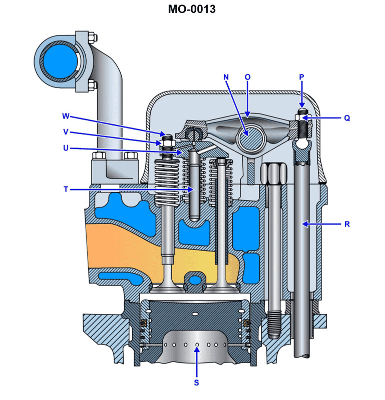
Question: The component shown in the illustration, labeled "I", is the_______________. Illustration MO-0013
A. first reduction pinion
B. first reduction gear
C. second reduction pinion
D. second reduction gear
The correct answer is B) first reduction gear. The first reduction gear is a key component in the transmission system of a marine vessel, responsible for transferring power from the engine to the propeller shaft. It is the larger of the two gears in the first stage of the reduction gearbox, which helps to step down the high engine speed to a lower, more suitable speed for the propeller. The other answer options are incorrect because: A) the first reduction pinion is the smaller gear in the first stage, C) the second reduction pinion is part of the second stage of the reduction gearbox, and D) the second reduction gear is the larger gear in the second stage.
Question 99
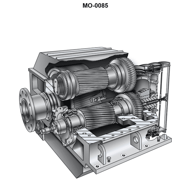
Question: What would be the most accurate description of the illustrated cutaway drawing of a reduction gear as used for medium-speed diesel propulsion? Illustration MO-0085
A. Single input, single reduction, non-reversing gear
B. Single input, double reduction, non-reversing gear
C. Single input, double reduction, reversing gear
D. Single input, single reduction, reversing gear
The correct answer is D) Single input, single reduction, reversing gear. This is the most accurate description based on the illustration MO-0085, which depicts a cutaway drawing of a reduction gear used for medium-speed diesel propulsion. A single input shaft from the diesel engine is connected to a single reduction gear, and the gear is designed to be reversible, allowing the propeller to rotate in both forward and reverse directions. The other options are incorrect because they do not accurately match the illustration. Option A describes a non-reversing gear, Option B describes a double reduction gear, and Option C describes a double reduction reversing gear, none of which are shown in the provided illustration.
Question 99
Question: What would be the most accurate description of the illustrated cutaway drawing of a reduction gear as used for medium-speed diesel propulsion? Illustration MO-0085
A. Single input, single reduction, non-reversing gear
B. Single input, double reduction, non-reversing gear
C. Single input, double reduction, reversing gear
D. Single input, single reduction, reversing gear
The correct answer is D) Single input, single reduction, reversing gear. The cutaway drawing in illustration MO-0085 shows a reduction gear with reversing capability, identifiable by the clutch mechanisms that allow the output shaft to rotate in either direction. The single input design accepts power from one engine, and the single reduction stage indicates one gear mesh between input and output. The reversing feature is essential for vessels with fixed-pitch propellers that require reverse thrust for maneuvering. Options A and B describe non-reversing configurations which would lack the clutching mechanisms visible in the illustration. Option C incorrectly identifies it as a double reduction gear, but the illustration shows only one reduction stage between input and output shafts.
Question 144
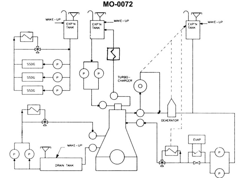
Question: According to the illustrated diesel propulsion plant fresh water cooling systems diagram, in which subsystem is the deaerator located? Illustration MO-0072
A. Main engine cylinder jacket cooling water system
B. Main engine fuel injector cooling water system
C. SSDG cylinder jacket cooling water system
D. Main engine piston cooling water system
The correct answer is A) Main engine cylinder jacket cooling water system. The deaerator is typically located in the main engine cylinder jacket cooling water system, which is responsible for removing dissolved gases from the cooling water to prevent corrosion and cavitation in the engine. This is a key component of the diesel propulsion plant fresh water cooling system, as maintaining the proper water quality is essential for the reliable operation of the main engine. The other answer choices do not accurately represent the location of the deaerator, as the fuel injector cooling, SSDG cylinder jacket, and piston cooling systems are separate subsystems within the overall diesel propulsion plant cooling arrangement.
Question 145
Question: According to the illustrated main and auxiliary diesel engine cooling water systems diagram, which of the following heat exchangers are connected directly in series with one another? Illustration MO-0129
A. Camshaft lube oil cooler and jacket water cooler
B. Jacket water cooler and scavenge air coolers(s)
C. Lube oil cooler and jacket water cooler
D. Camshaft lube oil cooler and scavenge air coolers(s)
The correct answer is C) Lube oil cooler and jacket water cooler. This is correct because in a typical marine diesel engine cooling water system, the lube oil cooler and jacket water cooler are connected in series. The cooling water circulates through the lube oil cooler first to remove heat from the engine oil, then continues on to the jacket water cooler to remove heat from the engine coolant. The other options are incorrect because the camshaft lube oil cooler and scavenge air coolers are not directly connected in series, and the jacket water cooler is not directly connected in series with the scavenge air coolers.
Question 154
Question: The lube oil strainer shown in the illustration is used on the reduction gear of a mid- size diesel engine. The strainer elements consist of_______________. Illustration MO-0057
A. fibrous braid
B. wire mesh
C. pleated paper
D. metal disks
The correct answer is D) metal disks. The lube oil strainer shown in the illustration MO-0057 is typically used on the reduction gear of a mid-size diesel engine. The strainer elements in this type of strainer consist of metal disks, which are designed to remove larger particles and contaminants from the lubricating oil before it enters the reduction gear. This helps to protect the reduction gear components from wear and damage. The other answer choices are incorrect because fibrous braid (A), wire mesh (B), and pleated paper (C) are not the typical strainer elements used in this type of lube oil strainer for a mid-size diesel engine reduction gear.
Question 160
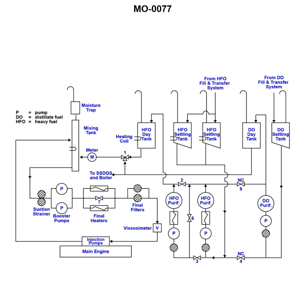
Question: According to the illustrated diesel engine fuel treatment and fuel service systems schematic, what is the purpose of the valve labeled "1"? Illustration MO-0077
A. HFO/DO fuel mixing valve for main engine
B. HFO/DO fuel changeover valve for auxiliary engines (and boiler)
C. HFO/DO fuel changeover valve for main engine
D. HFO/DO fuel mixing valve for auxiliary engines (and boiler)
The correct answer is C) HFO/DO fuel changeover valve for main engine. The valve labeled "1" in the illustration MO-0077 is used to switch the fuel supply between Heavy Fuel Oil (HFO) and Diesel Oil (DO) for the main engine. This allows the engine to operate on either HFO or DO, depending on the fuel availability and operational requirements. The changeover valve ensures a smooth transition between the two fuel types, which is necessary for the proper functioning and efficiency of the main engine. The other options are incorrect because they do not accurately describe the purpose of the valve labeled "1". Option A refers to a fuel mixing valve, while option B and D describe changeover valves for the auxiliary engines and boiler, which are separate from the main engine fuel system.
Question 162
Question: Valve '1', as shown in the illustration, should be operated when_______________. Illustration MO-0077
A. entering or departing port
B. starting auxiliary boilers
C. viscosimeter 'V' measures low viscosity
D. mixing tank is 'full'
The correct answer is A) entering or departing port. Valve '1' is likely a seacock or similar valve that controls the flow of water into or out of the vessel. During port operations when entering or departing, it is crucial to properly operate this valve to ensure water integrity and prevent flooding. The other answer choices do not directly relate to the function and proper operation of this type of valve.
Question 170
Question: According to the illustrated diesel engine fuel treatment and fuel service systems schematic, what would be the appropriate valve configuration for operating the two heavy fuel oil purifiers in series? Illustration MO-0077
A. Valves 2, 3, and 6 all OPEN
B. Valves 2, 3, and 6 all CLOSED
C. Valves 2 and 3 OPEN, and Valve 6 CLOSED
D. Valves 2 and 3 CLOSED, and Valve 6 OPEN
The correct answer is D) Valves 2 and 3 CLOSED, and Valve 6 OPEN. This configuration allows the two heavy fuel oil purifiers to operate in series, with the fuel flowing through Valve 6 and being purified by both purifiers. Valves 2 and 3 are closed to isolate the individual purifiers and force the fuel to pass through both in sequence. This is the appropriate valve configuration for operating the two purifiers in series, as indicated by the schematic. The other answer choices are incorrect because they do not properly isolate the purifiers and allow the fuel to flow through both units in series.
Question 172
Question: According to the illustrated diesel engine fuel treatment and fuel service systems schematic, what statement is true concerning the valves labeled "4" and "5"? Illustration MO-0077
A. Valves 4 and 5 are closed during normal operation, but when opened will allow one of the HFO purifiers to be used as a backup DO purifier, should the DO purifier become disabled.
B. Valves 4 and 5 are closed during normal operation, but when opened will allow the DO purifier to be used as a backup HFO purifier, should one of the HFO purifiers become disabled.
C. Valves 4 and 5 are closed during normal operation, but when opened will allow all three purifiers to centrifuge HFO while in series.
D. Valves 4 and 5 are closed during normal operation, but when opened will allow all three purifiers to centrifuge HFO while in parallel.
The correct answer is A. Valves 4 and 5 are closed during normal operation, but when opened, they will allow one of the HFO (heavy fuel oil) purifiers to be used as a backup DO (diesel oil) purifier, should the primary DO purifier become disabled. This allows the system to maintain diesel oil purification if the main DO purifier fails. The other options are incorrect because they do not accurately describe the function of valves 4 and 5 in the fuel treatment and fuel service systems schematic. Option B is incorrect because the valves do not allow the DO purifier to be used as a backup for the HFO purifiers. Options C and D are incorrect because the valves do not allow all three purifiers to be used in series or parallel for HFO purification.
Question 176
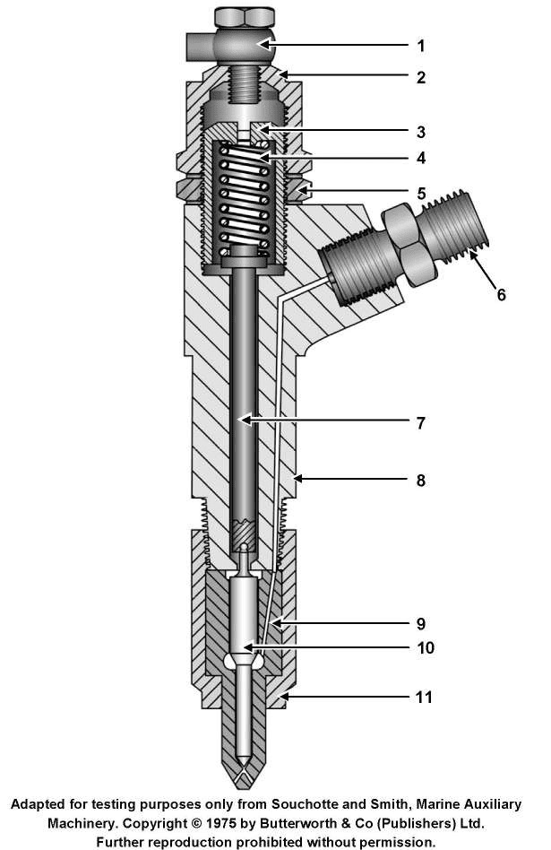
Question: The illustrated device is operated directly by_______________. Illustration MO-0041
A. a rocker arm and push rod
B. fuel oil pressure
C. cam action
D. excessively high combustion pressure
The correct answer is B) fuel oil pressure. The illustrated device is likely a fuel injector, which is operated directly by the fuel oil pressure in the fuel system. The fuel oil pressure is what forces the fuel through the injector nozzle and into the engine cylinder, allowing the engine to function. The other answer choices are incorrect because: A) a rocker arm and push rod are not involved in the direct operation of a fuel injector, C) cam action is not the primary driver of a fuel injector, and D) excessively high combustion pressure would not be the direct operating mechanism for a fuel injector.
Question 185
Question: What type of clutch is used in the illustrated medium-speed diesel engine reduction gear? Illustration MO-0085
A. Pneumatic
B. Mechanical
C. Electromagnetic
D. Hydraulic
The correct answer is A) Pneumatic. The illustration MO-0085 depicts a medium-speed diesel engine reduction gear, which typically utilizes a pneumatic clutch. Pneumatic clutches are commonly used in marine applications as they provide a smooth and controlled engagement of the gear, which is essential for the safe operation of the vessel. The pneumatic system allows for precise control of the clutch engagement, ensuring a gradual and controlled transfer of power from the engine to the reduction gear and ultimately to the propeller shaft. The other options are not commonly used in this type of marine reduction gear system. Mechanical clutches may be used in some applications, but they are less suitable for the smooth and precise control required in a marine environment. Electromagnetic and hydraulic clutches are less common in this specific application.
Question 186
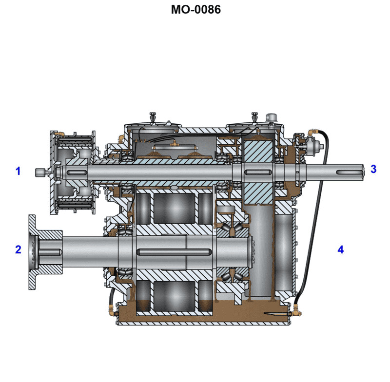
Question: The pinion gear shown in the illustration, is located . Illustration MO-0086
A. below "2" and "4"
B. between "2" and "4"
C. between "1" and "3"
D. below "1" and "3"
The correct answer is C) between "1" and "3". The pinion gear shown in the illustration MO-0086 is located between the numbers "1" and "3", which corresponds to answer choice C. The other answer choices are incorrect because: A) the pinion gear is not located below the numbers "2" and "4"; B) the pinion gear is not between the numbers "2" and "4"; and D) the pinion gear is not located below the numbers "1" and "3".
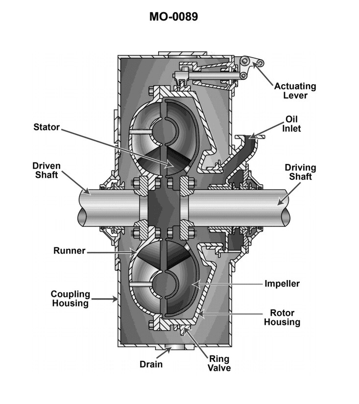
Question 187
Question: What type of clutch is pictured in the illustration? Illustration MO-0089
A. Mechanical
B. Hydraulic
C. Electromagnetic
D. Pneumatic
The correct answer is B) Hydraulic. The illustration MO-0089 likely depicts a hydraulic clutch system, which is commonly used in marine propulsion systems. Hydraulic clutches use fluid pressure to engage and disengage the clutch, providing smooth and controlled power transmission between the engine and the propeller shaft. The other options are incorrect because: A) Mechanical clutches use physical components like gears or plates to transmit power, B) Electromagnetic clutches use an electromagnetic field to engage the clutch, and D) Pneumatic clutches use compressed air to actuate the clutch, none of which are consistent with the illustration provided.