Pass Your Coast Guard Licensing Exams!
Study offline, track your progress, and simulate real exams with the Coast Guard Exams app
Safety & Environmental - Assistant
19 images
Question 1
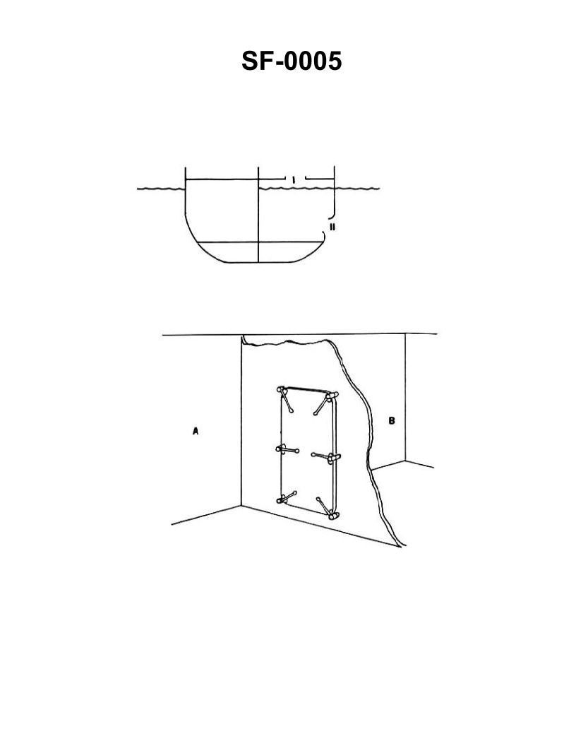
Question: You are in compartment "A", shown in the illustration, and suspect a fire in compartment "B". In order to check for and confirm the fire in compartment "B" you should _______________. Illustration SF-0005
A. feel the bulkhead
B. tap the bulkhead
C. open the watertight door
D. move a lighted candle along watertight door seal
The correct answer is A) feel the bulkhead. The reasoning for this is that in the event of a suspected fire, the proper procedure is to feel the bulkhead (the wall separating the compartments) with the back of your hand before opening any access points. This is to determine if the bulkhead is hot, which would indicate a fire on the other side. Opening the watertight door (option C) or moving a lighted candle along the seal (option D) could potentially provide oxygen to the fire and cause it to spread, which should be avoided. Tapping the bulkhead (option B) would not provide the same information as feeling it for heat. Therefore, option A, feeling the bulkhead, is the correct and safest approach to confirm the presence of a fire in the adjacent compartment.
Question 9
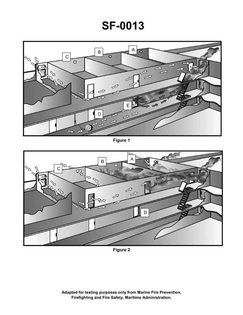
Question: What is the purpose of opening the doors and portholes in figure 2 of the illustration? Illustration SF-0013
A. To keep the hose teams cool.
B. To allow water used to fight the fire to flow out of the superstructure.
C. To allow venting of combustion products from the fire to the atmosphere.
D. To provide air flow around the compartment in the order to contain the fire.
The correct answer is C) To allow venting of combustion products from the fire to the atmosphere. Opening the doors and portholes in this scenario helps vent the smoke and other combustion products from the fire to the outside atmosphere. This improves visibility and reduces the buildup of toxic fumes inside the compartment, which is critical for the safety of the firefighting crew. The other options are incorrect because they do not address the primary purpose of venting the combustion products. Allowing water drainage (B) and providing air flow (D) are secondary benefits, but the main reason is to remove the hazardous smoke and gases from the enclosed space.
Question 20
Question: A large fire has developed in the HFO centrifuge room accessed by door "E". To combat the fire you should _______________. Illustration SF-0013
A. only need to set up a hose team to cool the door, then open the door and extinguish the fire using a type B-II extinguisher
B. advance the hose team into the room without any additional preparatory action
C. cool adjoining horizontal and vertical surfaces before opening the door to extinguish the fire
D. keep the door tightly closed until all the oil has been consumed by the fire
The correct answer is C) Cool adjoining horizontal and vertical surfaces before opening the door to extinguish the fire. This is the correct answer because when dealing with a fire in an enclosed space, such as the HFO centrifuge room, it is crucial to first cool the surrounding surfaces before opening the door. This helps prevent the sudden rush of air and potential backdraft that could occur when the door is opened, which could worsen the fire. Cooling the surfaces also helps limit the spread of the fire to adjacent areas. The other options are incorrect because they do not adequately address the need to cool the surrounding area before attempting to extinguish the fire directly.
Question 129
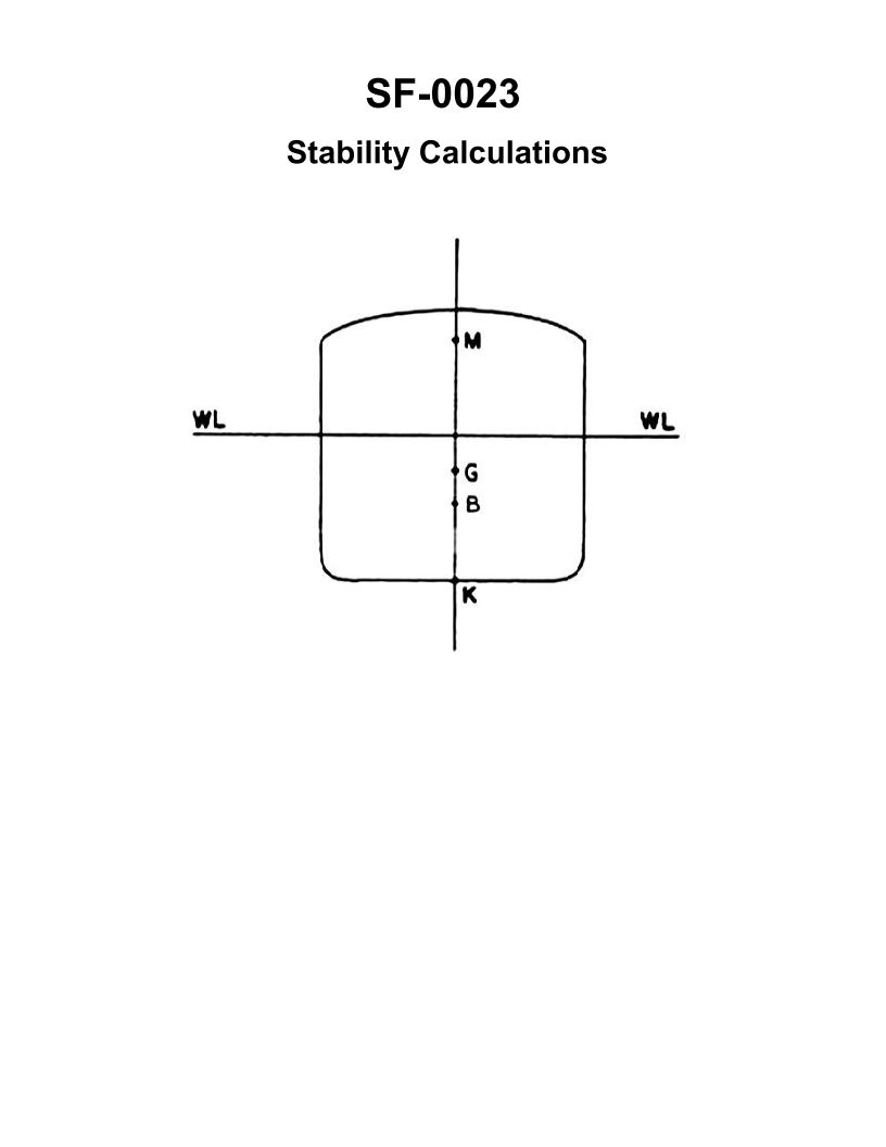
Question: If additional weight is placed on the main deck of the vessel shown in the illustration _______________. Illustration SF-0023
A. KB will go down
B. GM will increase
C. G will rise
D. K will rise
The correct answer is C) G will rise. When additional weight is placed on the main deck of a vessel, the vessel's center of gravity (G) will rise. This is because the added weight increases the overall weight of the vessel, which causes the center of gravity to shift upwards. As the center of gravity (G) rises, the vessel's stability is reduced, as indicated by a decrease in the metacentric height (GM). The other options are incorrect because: A) KB (the distance between the vessel's center of buoyancy and the keel) will not go down, as it is not directly affected by the added weight on the deck. B) GM (the metacentric height) will decrease, not increase, due to the rise in the center of gravity (G). D) K (the position of the keel) will not rise, as the keel remains fixed in position.
Question 139
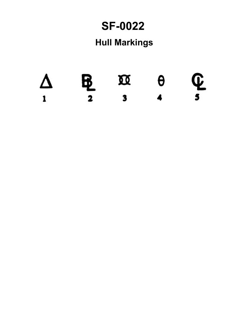
Question: The symbol shown in the illustration used to represent displacement is _______________. Illustrations SF-0022
A. 1
B. 2
C. 3
D. 4
The correct answer is A) 1. The symbol 1 is used to represent displacement in the illustration SF-0022 referenced in the question. Displacement is a fundamental naval architecture concept that refers to the weight of the water displaced by a vessel, which is equal to the weight of the vessel itself. This symbol is the standard way to denote displacement in technical illustrations and diagrams related to ship design and operation. The other options (B, C, and D) do not correspond to the symbol used for displacement in the given illustration.
Question 140
Question: Symbol number "3" shown in the illustration represents which of the following? Illustration SF-0022
A. amidships
B. baseline
C. forward perpendicular
D. displacement
The correct answer is A) amidships. The illustration SF-0022 is a diagram used for US Coast Guard Captain's License Examinations. In this diagram, symbol number "3" represents the amidships, which is the midpoint of the vessel's length. This is the standard designation for the amidships location on ship diagrams and schematics. The other answer choices are incorrect because: B) baseline refers to the lowest point of the vessel's hull, C) forward perpendicular is the front of the vessel, and D) displacement is the volume of water a vessel displaces, not a point on the vessel itself.
Question 141
Question: The symbol shown in the illustration and is used as the reference from which transverse measurements are made is _______________. Illustration SF-0022
A. 5
B. 4
C. 3
D. 1
The correct answer is A) 5. The symbol shown in the illustration SF-0022 is the station number 5, which is used as the reference from which transverse measurements are made. This is a standard practice in the US Coast Guard Captain's License Examinations, where station numbers are used to indicate specific locations on a vessel's frame for taking measurements and conducting stability calculations. The other options (B, C, and D) are incorrect because they do not correspond to the station number shown in the provided illustration.
Question 148
Question: The symbol shown in the illustration and used as a reference, from which the height of the center of gravity is measured, is item number _______________. Illustration SF-0022
A. 5
B. 4
C. 3
D. 2
The correct answer is D. The symbol shown in the illustration SF-0022, from which the height of the center of gravity is measured, is item number 2. This is based on the information provided in the illustration, which clearly labels item 2 as the "Center of Gravity" symbol. The other answer choices are incorrect because item 5 represents the "Longitudinal Center of Gravity", item 4 represents the "Vertical Center of Gravity", and item 3 does not appear to be the relevant symbol for measuring the height of the center of gravity according to the information provided in the illustration.
Question 176
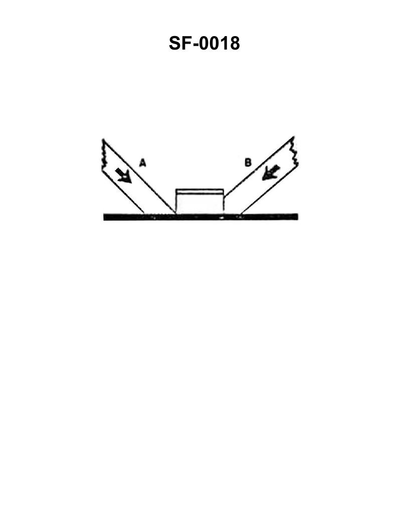
Question: The wooden shoring shown in the illustration is bearing against the hatch coaming and is supporting a load in the direction indicated by the arrows. Which of the following statements is correct for this condition? Illustration SF-0018
A. Shore "A" will support the greatest load.
B. Shore "A" will not slip under load.
C. Shore "B" will support the load without it cracking.
D. Shore "B" will crack at the pointed end.
The correct answer is C) Shore "B" will support the load without it cracking. The reasoning is that shore "B" is positioned at a right angle to the hatch coaming, which provides a stable and secure support for the load. The flat end of shore "B" distributes the load evenly, preventing it from cracking under the pressure. In contrast, shore "A" is not aligned at a right angle, making it more likely to slip or fail under the load. The other options are incorrect because: A) Shore "A" may not support the greatest load due to its unfavorable angle; B) Shore "A" could still slip under load due to the angled positioning; and D) Shore "B" is less likely to crack at the pointed end since it is designed to bear the load at the flat end.
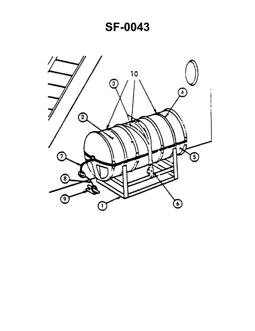
Question 184
Question: In the illustration shown, the sea painter is identified as item number _______________. Illustration SF-0043
A. 3
B. 6
C. 7
D. 9
The correct answer is C) 7. The sea painter is identified as item number 7 in the illustration SF-0043. This is based on the regulations and requirements for the US Coast Guard Captain's License Examinations, which specify the components and labeling of various maritime equipment and gear. The other answer choices are incorrect because item 3 is the anchor, item 6 is the anchor chain, and item 9 is the riding pawl, none of which are the sea painter as depicted in the illustration.
Question 231
Question: In figure 1 of the illustration, fire would spread to compartment "B" by _______________. Illustration SF-0013
A. convection
B. radiation
C. conduction
D. impingement
The correct answer is C) conduction. Fire spread by conduction occurs when heat travels through a solid material, such as the bulkhead or wall separating the two compartments. In the illustration SF-0013, fire in compartment "A" would conduct heat through the solid bulkhead or wall, eventually causing the temperature to rise in the adjacent compartment "B", leading to the spread of the fire. The other options are incorrect because: A) convection involves the transfer of heat through a fluid, such as air or water, which is not the primary mode of fire spread in this case; B) radiation involves the transfer of heat through electromagnetic waves, which is not the dominant mechanism here; and D) impingement refers to the direct contact of the flame or hot gases with the adjacent surface, which is not the primary focus of the question.
Question 236
Question: The air flow depicted in figure 1 of the illustration is an example of which type of ventilation? Illustration SF-0013
A. Combination.
B. Vertical.
C. Horizontal.
D. Parallel.
The correct answer is A) Combination. The air flow depicted in figure 1 of the illustration SF-0013 is an example of combination ventilation. Combination ventilation refers to a system that uses both vertical and horizontal air flow to effectively circulate and distribute air throughout a space. This type of ventilation combines the advantages of both vertical and horizontal air movement to provide efficient and well-distributed ventilation. The other options are incorrect because vertical ventilation involves only vertical air flow, horizontal ventilation involves only horizontal air flow, and parallel ventilation refers to a specific type of duct arrangement, which is not depicted in the illustration.
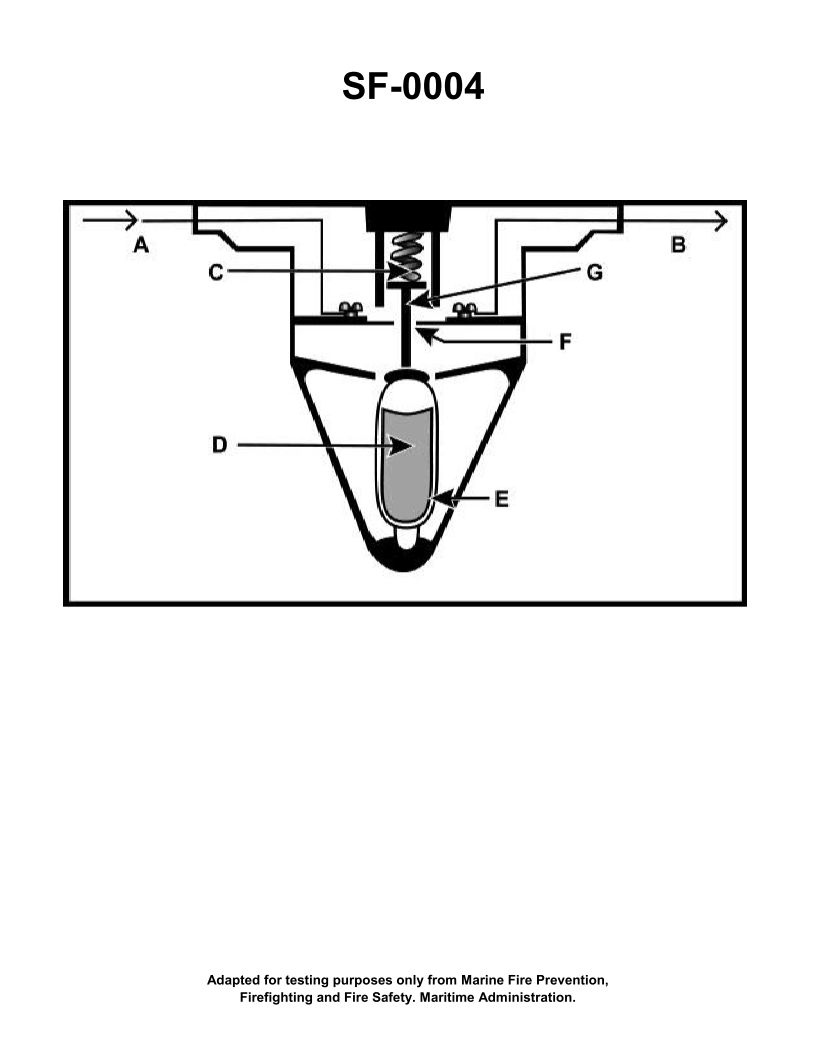
Question 262
Question: The component shown in the illustration would be installed in which of the following types of fire detection systems? Illustration SF-0004
A. Line-type pneumatic
B. Fixed temperature
C. Rate-of-rise
D. Combined fixed temperature and rate-of-rise
The correct answer is B. Fixed temperature. The component shown in the illustration SF-0004 is a fixed temperature fire detector. This type of detector is designed to activate when the surrounding temperature reaches a predetermined fixed temperature, typically between 135°F and 174°F. Fixed temperature detectors are commonly used in fire detection systems where a rapid rise in temperature is expected in the event of a fire. The other options are incorrect because: A) Line-type pneumatic detectors use air pressure changes to detect fires, C) Rate-of-rise detectors activate based on the speed of temperature increase, and D) Combined fixed temperature and rate-of-rise detectors use both fixed temperature and rate-of-rise principles, but the component shown is specifically a fixed temperature detector.
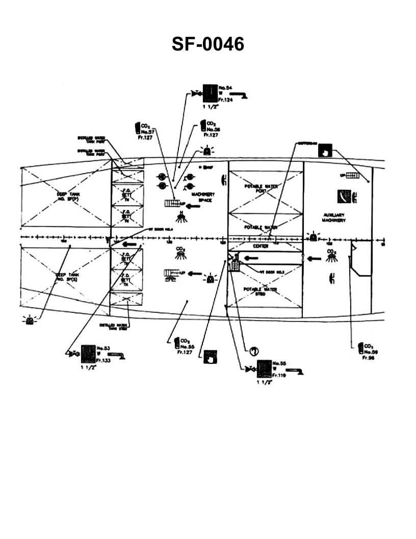
Question 265
Question: You are part of a search team and have been told that the last sighting of the wiper was next to the fire pump(s). What is the location of the fire pump(s)? Illustration SF-0046
A. Auxiliary machinery space, starboard side, frame 104
B. Machinery space, starboard side, frame 123
C. Machinery space, port side, frame 127
D. Machinery space, port side, frame 131
The correct answer is D) Machinery space, port side, frame 131. The location of the fire pump(s) is typically found in the machinery space, on the port side, at frame 131. This is a common configuration for the placement of fire pumps on commercial vessels, as it provides easy access and a centralized location for this critical safety equipment. The other answer choices are incorrect because they do not accurately reflect the standard location of fire pumps on commercial vessels. Auxiliary machinery spaces, the starboard side, and frames other than 131 are not the typical locations for fire pumps.
Question 266
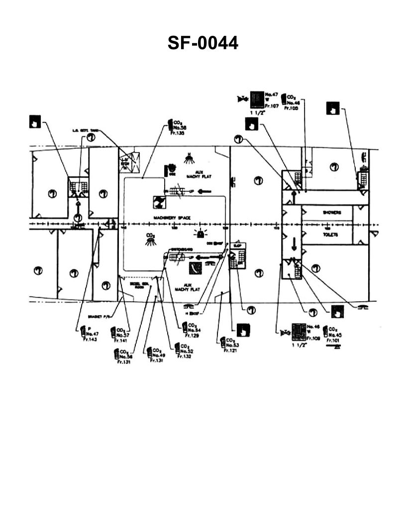
Question: If there was a fire out of control on the Auxiliary Machinery Flat, what fixed extinguishing system in that space would be the best means to extinguish the fire? Illustration SF-0044
A. Drenching
B. Carbon Dioxide
C. Halon
D. Water
The correct answer is C) Halon. The Auxiliary Machinery Flat is a machinery space, and for this type of space, the most effective fixed extinguishing system is typically a Halon system. Halon systems are highly effective at extinguishing fires in enclosed machinery spaces by rapidly reducing the oxygen content and interrupting the chemical chain reaction of the fire. The other options, such as drenching (A) or a water-based system (D), would not be as effective in this type of machinery space. Carbon dioxide (B) systems can also be used, but Halon is generally considered the optimal choice for machinery space fire suppression.
Question 267
Question: On the illustrated fire control plan of the lower engine room, the arrow between frames 135 and 140 represents what? Illustration SF-0046
A. Direction of fire main
B. Primary means of escape
C. Secondary means of escape
D. Missing person search pattern
The correct answer is B) Primary means of escape. The arrow between frames 135 and 140 on the illustrated fire control plan of the lower engine room represents the primary means of escape from that compartment. This is a standard requirement for fire control plans to clearly indicate the designated evacuation routes in the event of an emergency. The other answer choices are incorrect because they do not accurately describe the function of this particular element on the fire control plan.
Question 338
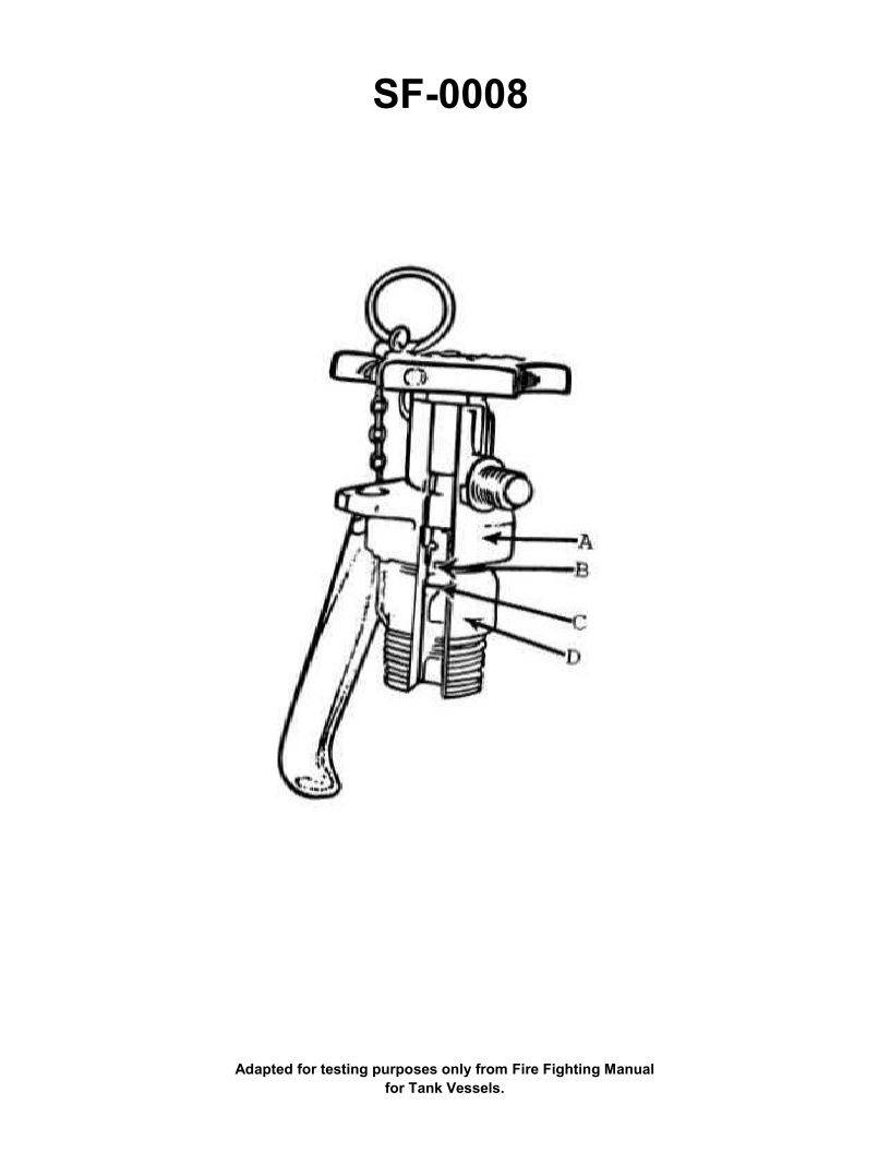
Question: To operate a carbon dioxide extinguisher having the type of head shown in the illustration, you would _______________. Illustration SF-0008
A. open valve and pull pin
B. pull pin and open valve
C. pull pin, open valve, and pull up on release lever
D. open valve, pull pin, and pull up on release lever
The correct answer is B) pull pin and open valve. To operate a carbon dioxide (CO2) extinguisher with the type of head shown in the illustration SF-0008, you would first need to pull the pin and then open the valve. This is the correct sequence because the pin secures the valve, preventing accidental discharge. Once the pin is pulled, the valve can be opened to release the CO2 agent. The other options are incorrect because they either have the steps out of order (A and D) or include an unnecessary step of pulling up on a release lever, which is not present on this type of CO2 extinguisher (C).
Question 343
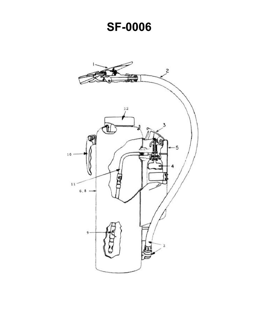
Question: Which of the following statements is true concerning the fire extinguisher shown in the illustration? Illustration SF-0006
A. The agent may be applied in short bursts by opening and closing the squeeze nozzle piece No.1.
B. The illustrated extinguisher must never be used in conjunction with water.
C. The initial discharge of the extinguisher should be at close range to scatter the burning material.
D. There is no danger of reflash in using the illustrated extinguisher on a class B fire.
The correct answer is A) The agent may be applied in short bursts by opening and closing the squeeze nozzle piece No.1. This is correct because the illustration shows a portable fire extinguisher, likely a CO2 or dry chemical type, which is intended to be used by discharging the agent in short bursts to control the fire. Continuously discharging the entire contents may not be as effective. The other answer choices are incorrect - B) is wrong because the extinguisher should not be used on water-based fires, C) is incorrect as the extinguisher should be used from a safe distance, not at close range, and D) is false as there is a risk of reflash when using this type of extinguisher on Class B (flammable liquid) fires.
Question 347
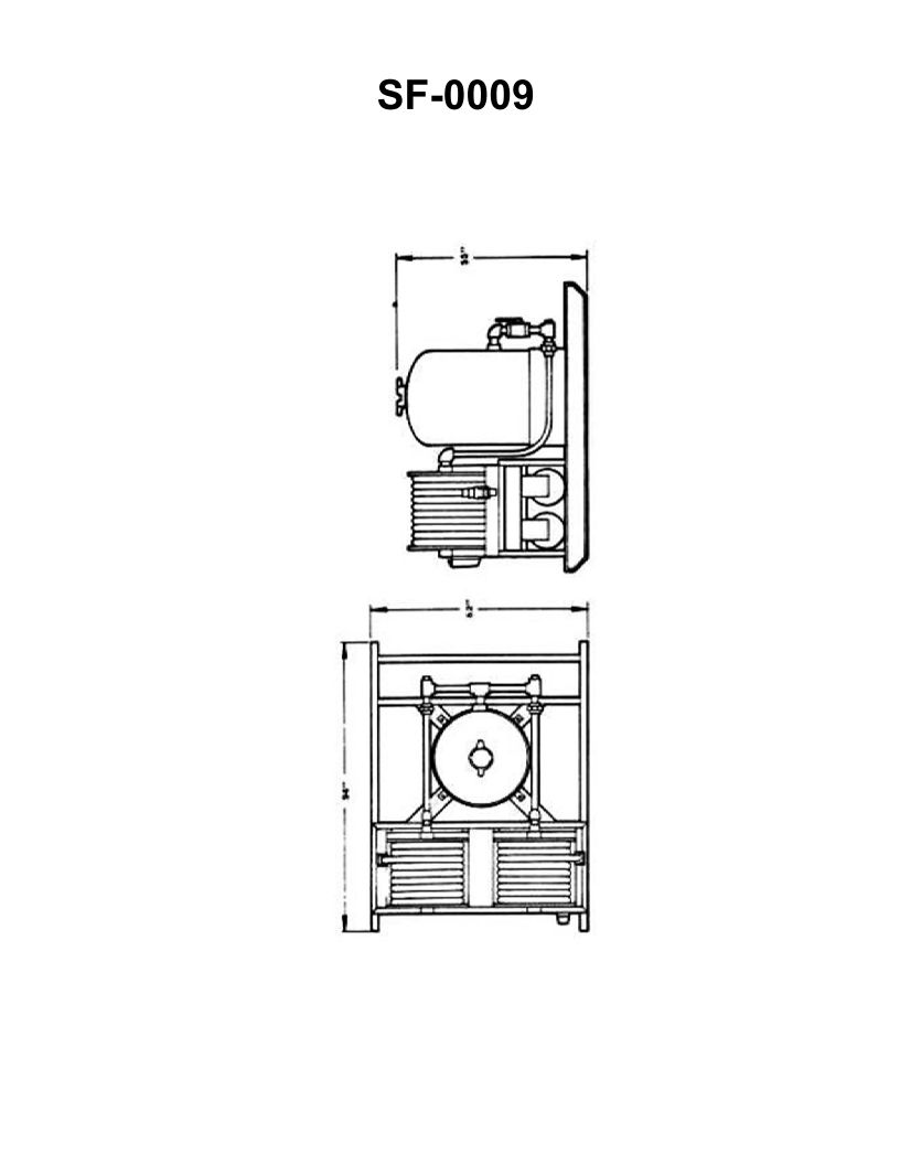
Question: The fire extinguishing equipment shown in the illustration is a large _______________. Illustration SF-0009
A. Halon 1301 hose reel system
B. CO2 hose reel system
C. light water hose reel system
D. dry chemical hose reel system
The correct answer is D) dry chemical hose reel system. The illustration SF-0009 is depicting a dry chemical hose reel system, which is a common type of fire extinguishing equipment found on ships and vessels. Dry chemical extinguishers use a dry powder agent that is effective against Class A, B, and C fires, making them a versatile choice for marine applications. The other options are incorrect because: A) Halon 1301 systems are less common nowadays due to environmental concerns, B) CO2 systems require more specialized handling, and C) light water systems are generally used for Class B and C fires, but may not be as effective on solid combustible materials.