Pass Your Coast Guard Licensing Exams!
Study offline, track your progress, and simulate real exams with the Coast Guard Exams app
Safety & Environmental - 1st Asst/Chief
22 images
Question 5
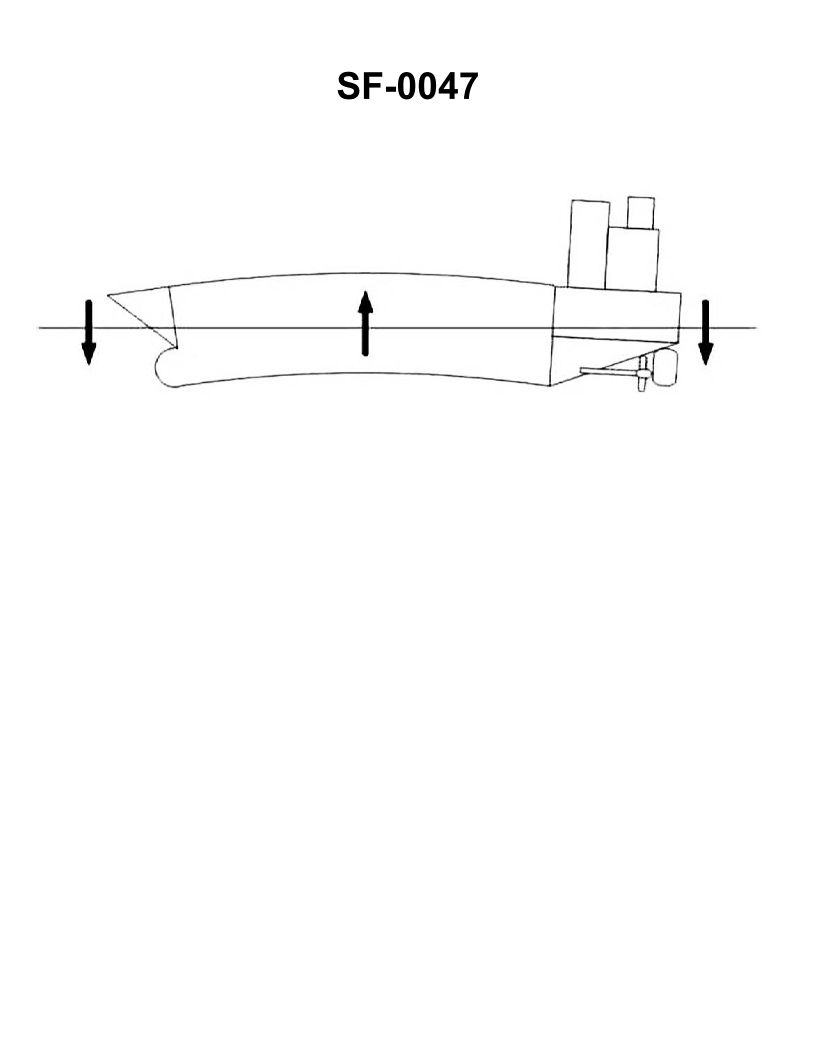
Question: Following cargo loading operations, your vessel is experiencing an excessive at-sea hogging bending stress as shown in the illustration. What should you do to reduce the bending moment? See Illustration SF-0047
A. Add ballast to the forepeak tank.
B. Add ballast to an amidships tank.
C. Add ballast to the after peak tank.
D. Remove ballast from an amidships tank.
The correct answer is B) Add ballast to an amidships tank. Explanation: Adding ballast to an amidships tank helps reduce the excessive hogging bending stress by shifting more weight towards the center of the vessel. This counteracts the bending moment caused by the cargo loading, bringing the vessel back into a more even trim and reducing the hogging stress. The other options are incorrect because: A) Adding ballast to the forepeak tank would not counteract the hogging stress, and may even exacerbate it. C) Adding ballast to the after peak tank would not effectively reduce the hogging stress. D) Removing ballast from an amidships tank would further increase the hogging stress.
Question 8
Question: Following cargo loading operations, your vessel is experiencing an excessive at-sea sagging bending stress as shown in the illustration. What should you do to reduce the bending moment? Illustration SF-0047
A. Remove ballast from an amidships tank.
B. Add ballast to the forepeak and after peak tanks.
C. Remove ballast to the after peak tank.
D. Add ballast to an amidships tank.
The correct answer is B) Add ballast to the forepeak and after peak tanks. This is the correct answer because adding ballast to the forepeak and after peak tanks helps to reduce the bending moment and excessive sagging stress on the vessel. By adding ballast to these end tanks, the vessel's weight distribution is shifted towards the ends, which counteracts the sagging effect and reduces the overall bending moment. The other options are incorrect because: A) Removing ballast from an amidships tank would further exacerbate the sagging issue; C) Removing ballast from the after peak tank would not address the sagging problem; and D) Adding ballast to an amidships tank would not effectively counteract the sagging stress.
Question 16
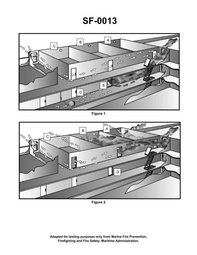
Question: The air flow depicted in figure 1 of the illustration is an example of which type of ventilation? Illustration SF-0013
A. Vertical.
B. Combination.
C. Horizontal.
D. Parallel.
The correct answer is B) Combination. The air flow depicted in figure 1 of the illustration SF-0013 represents a combination ventilation system, which uses both vertical and horizontal air flow patterns. Combination ventilation systems are commonly used in marine vessels to provide effective air circulation and prevent the buildup of stagnant air pockets. The other answer choices are incorrect because vertical ventilation only uses a vertical air flow (option A), horizontal ventilation only uses a horizontal air flow (option C), and parallel ventilation uses air flows that move in parallel directions (option D), which is not what is shown in the illustration.
Question 25
Question: In figure 1 of the illustration, fire would spread to compartment "B" by _______________. Illustration SF-0013
A. impingement
B. radiation
C. convection
D. conduction
The correct answer is D) conduction. In the context of fire spreading between compartments, conduction is the mechanism by which heat would transfer from one compartment to the adjacent compartment "B" through the common boundary or bulkhead. The heat generated in one compartment would be conducted through the metal or other solid materials of the bulkhead, allowing the fire to spread into the adjacent space by this mode of heat transfer. The other answer choices are incorrect because impingement refers to direct flame contact, radiation is heat transfer through electromagnetic waves, and convection is heat transfer by movement of hot gases or fluids - these modes of heat transfer are not the primary means by which the fire would spread from one compartment to the next as depicted in the illustration.
Question 44
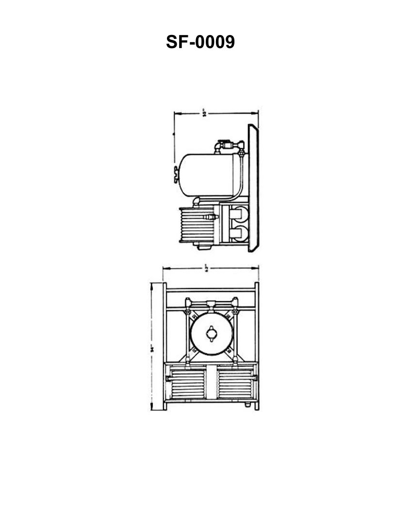
Question: The fire extinguishing equipment shown in the illustration is a large _______________. Illustration SF-0009
A. Halon 1301 hose reel system
B. CO2 hose reel system
C. light water hose reel system
D. dry chemical hose reel system
The correct answer is D) dry chemical hose reel system. The illustration SF-0009 is depicting a dry chemical hose reel system, which is a common type of fire extinguishing equipment found on many vessels. Dry chemical systems use a dry powder agent that is effective against Class B (flammable liquids) and Class C (energized electrical) fires. This makes them a suitable choice for many marine applications. The other options are incorrect because halon 1301 systems are less common today due to environmental concerns, CO2 systems are typically used for enclosed spaces, and light water systems are more specialized for certain types of fires.
Question 59
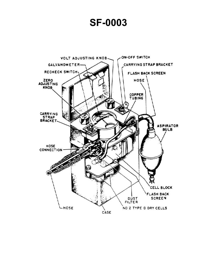
Question: Which of the following statements is true concerning the meter shown in the illustration? Illustration SF-0003
A. As gas samples are drawn into the instrument they are burned within the case.
B. If there is any liquid in the tank being tested, the sampling tube should be submerged in it to obtain the most accurate reading.
C. If the meter moves to the extreme right side of the scale and stays there, the atmosphere is safe.
D. Meter readings are obtained instantaneously upon release of the squeeze bulb.
The correct answer is A) As gas samples are drawn into the instrument they are burned within the case. This is correct because the meter shown in the illustration is a combustible gas detector, which works by drawing in a sample of the atmosphere and burning it within the instrument's case. The meter reading then indicates the concentration of combustible gases present. The other answer choices are incorrect because: B) Submerging the sampling tube in liquid would not provide an accurate reading, as the instrument is designed to sample the ambient atmosphere. C) A reading at the extreme right of the scale would indicate a high concentration of combustible gases, not a safe atmosphere. D) Meter readings are not instantaneous, as the instrument requires time to draw in and analyze the gas sample.
Question 60
Question: The instrument shown in the illustration has not been used for several weeks. Prior to its use for testing a compartment, you should _______________. Illustration SF-0003
A. check or renew the batteries
B. purge the meter
C. adjust the meter pointer to zero
D. all of the above
The correct answer is D) all of the above. When an instrument has not been used for several weeks, it is important to thoroughly check and prepare it before use to ensure accurate and reliable readings. This involves: 1) Checking or renewing the batteries to ensure the instrument has sufficient power to operate properly. 2) Purging the meter to remove any contaminants or residue that may have built up during the period of non-use. 3) Adjusting the meter pointer to zero to establish a proper baseline for taking measurements. Performing all these steps helps to confirm the instrument is in good working order and will provide accurate results when testing a compartment. The other answer choices, while potentially useful steps, do not encompass the full scope of preparation required for an instrument that has been idle for an extended period.
Question 67
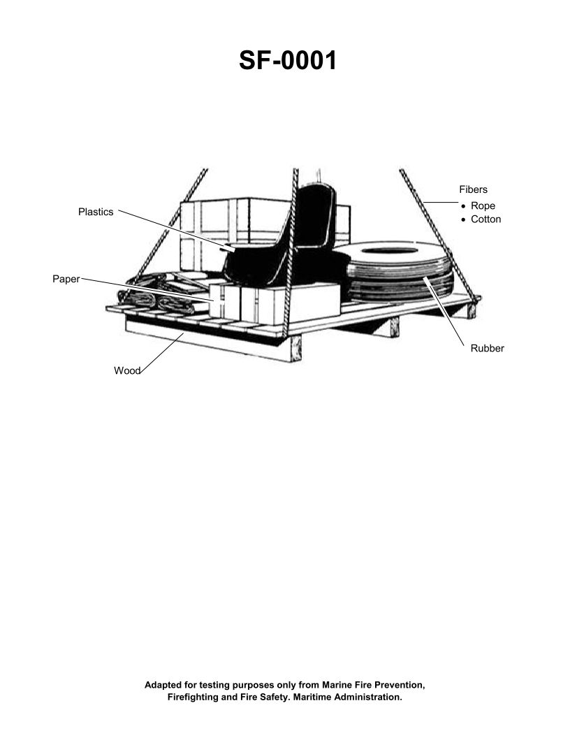
Question: If the items shown in the illustration are burning, this fire would be a Class _______________. Illustration SF-0001
A. "A"
B. "B"
C. "C"
D. "D"
The correct answer is A) "A". The illustration SF-0001 shows a fire involving flammable liquids and gases, which would be classified as a Class A fire according to the US Coast Guard Captain's License Examinations. Class A fires involve ordinary combustible materials such as wood, paper, cloth, and plastics. The key characteristic of a Class A fire is that it can be extinguished using water, which is the most effective extinguishing agent for this type of fire. The other answer choices are incorrect because Class B fires involve flammable liquids and gases (B), Class C fires involve energized electrical equipment (C), and Class D fires involve combustible metals (D), none of which accurately describe the fire depicted in the illustration.
Question 107
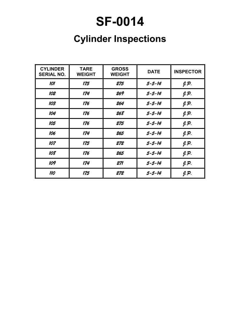
Question: During the annual servicing of your ship's fixed CO2 system, you receive the report shown in the illustration. Which CO2 cylinders require recharging? Illustration SF-0014
A. 109
B. 103 and 108
C. 105
D. All of the above
The correct answer is B) 103 and 108. The illustration SF-0014 shows the annual servicing report for a ship's fixed CO2 system. Based on the information provided, cylinders 103 and 108 require recharging, as their contents are less than the required minimum of 90% of the system's design capacity. The other cylinders, 105 and 109, are within the acceptable range and do not need recharging. The other answer choices are incorrect because: A) 109 is not the only cylinder that needs recharging, C) 105 is within the acceptable range, and D) not all cylinders require recharging.
Question 128
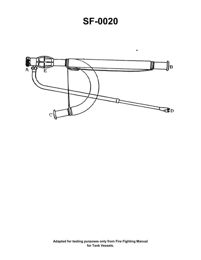
Question: As the senior engineer onboard a vessel, how would you instruct a new engineer to use the firefighting apparatus illustrated to fight an oil fire at the bunker station? Illustration SF-0020
A. This piece of firefighting equipment cannot be used to extinguish an oil fire.
B. Direct aqueous film forming foam off the overhead or nearby bulkhead, using a bank down or bounce off method to extinguish the fire.
C. Direct water off the overhead or nearby bulkhead, using a bank down or bounce off method to extinguish the fire.
D. Direct aqueous film forming foam in a straight stream into the fuel to extinguish the fire.
The correct answer is B) Direct aqueous film forming foam off the overhead or nearby bulkhead, using a bank down or bounce off method to extinguish the oil fire. This is the correct answer because aqueous film forming foam (AFFF) is the most effective agent for extinguishing an oil fire. AFFF forms a vapor-suppressing film on the surface of the burning liquid, smothering the fire. Applying the AFFF by bouncing it off a nearby surface allows the foam to spread over the oil fire's surface more effectively than a direct stream, which could splash the burning liquid. The other options are incorrect because A) water cannot be used on an oil fire as it will cause the fire to spread, C) a direct water stream is also ineffective against an oil fire, and D) directing AFFF in a straight stream into the fuel would be less effective than the bank down or bounce off method described in the correct answer.
Question 201
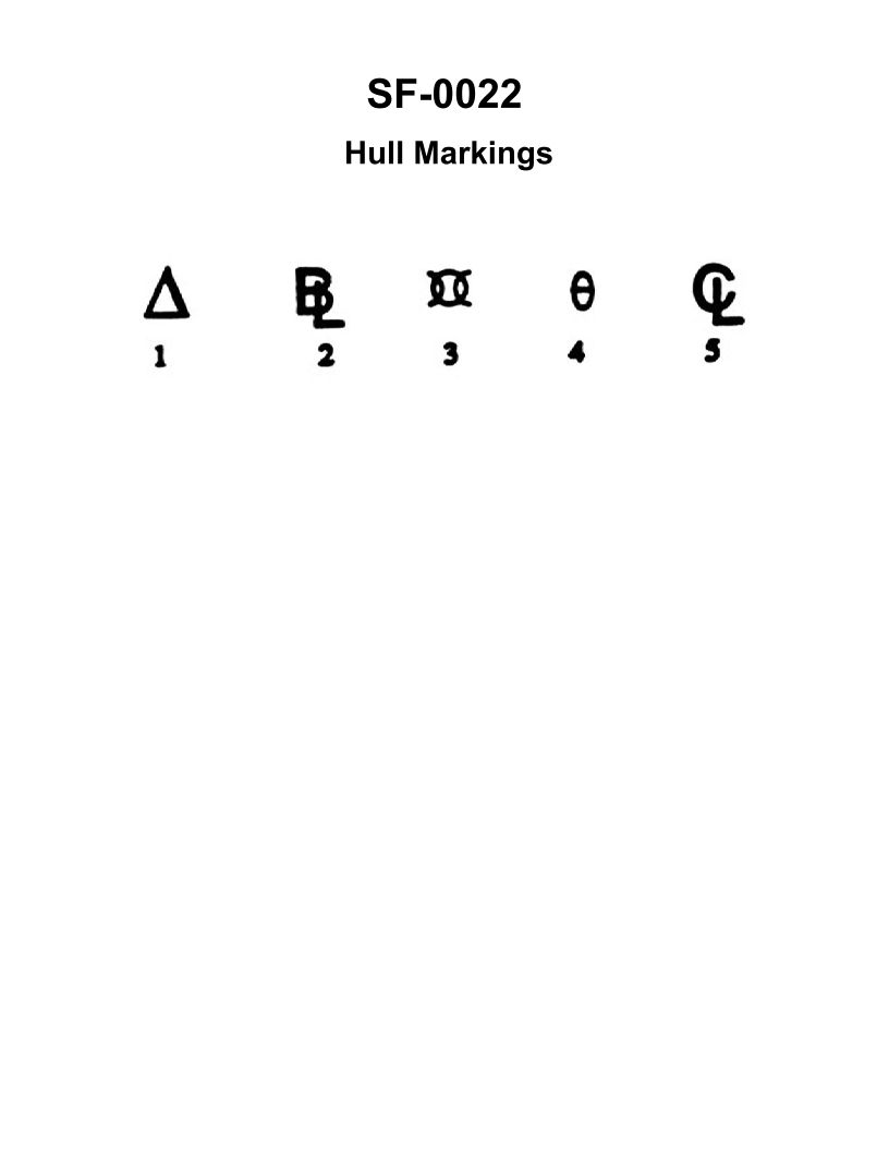
Question: The symbol shown in the illustration and used as a reference, from which the height of the center of gravity is measured, is item number _______________. Illustration SF-0022
A. 5
B. 4
C. 3
D. 2
The correct answer is D) 2. The illustration SF-0022 shows a diagram of a vessel, and the symbol or item number 2 represents the "reference point from which the height of the center of gravity is measured." This is the correct answer because the center of gravity is a critical parameter that must be determined for the stability calculations required in the Coast Guard Captain's License Examinations. The other options are incorrect because they do not correspond to the reference point for the center of gravity measurement, which is clearly identified as item number 2 in the illustration.
Question 232
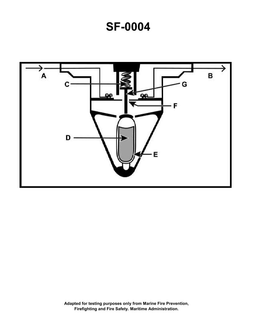
Question: The component shown in the illustration would be installed in which of the following types of fire detection systems? Illustration SF-0004
A. Fixed temperature
B. Line-type pneumatic
C. Combined fixed temperature and rate-of-rise
D. Rate-of-rise
The correct answer is A) Fixed temperature. The component shown in the illustration SF-0004 is a fixed temperature fire detector. This type of detector is used in fixed temperature fire detection systems, which are designed to activate when the surrounding temperature reaches a pre-determined fixed temperature threshold. This is in contrast to rate-of-rise detectors (option D), which activate based on the speed of temperature increase, or combined fixed temperature and rate-of-rise detectors (option C). Line-type pneumatic detectors (option B) use pressurized tubing to detect changes in pressure, rather than temperature.
Question 253
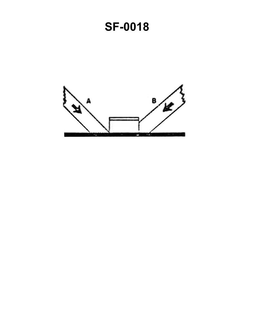
Question: The wooden shoring shown in the illustration is bearing against the hatch coaming and is supporting a load in the direction indicated by the arrows. Which of the following statements is correct for this condition? Illustration SF-0018
A. Shore "A" will support the greatest load.
B. Shore "A" will not slip under load.
C. Shore "B" will support the load without it cracking.
D. Shore "B" will crack at the pointed end.
The correct answer is C) Shore "B" will support the load without it cracking. The reasoning for this is that the pointed end of shore "B" is bearing against the hatch coaming, which provides a larger surface area for the load to be distributed. This reduces the stress on the wood, making it less likely to crack under the applied load. In contrast, shore "A" has a smaller bearing surface, so it would be more prone to failure. The other options are incorrect because: A) shore "A" may not necessarily support the greatest load due to the smaller bearing surface; B) shore "A" could still slip under load due to the smaller bearing area; and D) shore "B" may not necessarily crack at the pointed end, as the larger bearing surface helps distribute the load more evenly.
Question 276
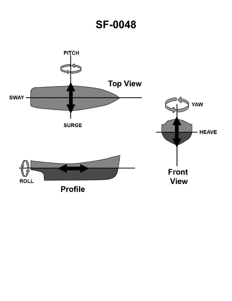
Question: The motion of a vessel impacts its stability. Which of these motions shown in the illustration affects the governing "positional motion" stability? Illustration SF-0048
A. Surge
B. Sway
C. Pitch
D. Heave
The correct answer is D) Heave. Heave is the vertical up-and-down motion of a vessel, which directly affects its positional stability. This is because the vessel's center of gravity moves up and down relative to the water, impacting the stability and balance of the vessel. The other motions listed - surge (forward/backward), sway (side-to-side), and pitch (bow up/down) - do not directly impact the vessel's positional stability in the same way as the heaving motion.
Question 278
Question: The motion of a vessel impacts its stability. Which of these motions shown in the illustration affects the governing "directional" stability? Illustration SF-0048
A. Pitch
B. Sway
C. Yaw
D. Surge
The correct answer is C) Yaw. Yaw is the motion of a vessel that describes its rotation around a vertical axis, which affects the vessel's directional stability. Directional stability is the ability of a vessel to maintain a straight course when subjected to external forces such as wind and waves. Yaw motion directly impacts the vessel's ability to maintain its heading, making it the relevant motion that affects directional stability. The other options, such as pitch (rotation around the transverse axis) and sway (sideways movement), do not directly influence the vessel's directional stability in the same way that yaw does. Surge (forward and backward movement) also does not impact directional stability.
Question 279
Question: The motion of a vessel impacts its stability. Which of these motions shown in the illustration affects the governing "longitudinal" stability? Illustration SF-0048
A. Yaw
B. Pitch
C. Heave
D. Surge
The correct answer is B) Pitch. Pitch is the motion of a vessel that affects its longitudinal stability. Longitudinal stability refers to the vessel's stability along its length, and pitch is the rotation of the vessel around its transverse axis, which influences this longitudinal stability. The other motions listed, such as yaw, heave, and surge, affect the vessel's stability in different ways, but do not directly impact the governing longitudinal stability.
Question 280
Question: The motion of a vessel impacts its stability. Which of these motions shown in the illustration affects the governing "transverse" stability? Illustration SF-0048
A. Sway
B. Surge
C. Pitch
D. Roll
The correct answer is D) Roll. The motion that affects the governing "transverse" stability of a vessel is roll. Transverse stability refers to a vessel's ability to resist capsizing or heeling over from side to side, which is primarily impacted by the vessel's roll motion. Sway, surge, and pitch are other motions that affect a vessel's stability, but they do not directly impact the critical transverse stability that is a key consideration in the US Coast Guard Captain's License Examinations.
Question 282
Question: The motion of a vessel impacts its stability. Which of these motions shown in the illustration affects the governing "motion ahead and astern" stability? Illustration SF-0048
A. Heave
B. Pitch
C. Yaw
D. Surge
The correct answer is D) Surge. Surge is the motion of a vessel along its longitudinal (fore-and-aft) axis, which affects the vessel's stability in the "motion ahead and astern" direction. This motion impacts the vessel's stability in the direction of travel, which is a key factor in the "motion ahead and astern" stability considered in the US Coast Guard Captain's License Examinations. The other options, heave (vertical motion), pitch (rotational motion about the transverse axis), and yaw (rotational motion about the vertical axis), do not directly affect the "motion ahead and astern" stability, which is the focus of the question.
Question 284
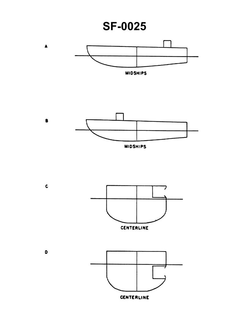
Question: If a vessel initially has no list and no significant trim, which of the developments shown in the illustration will result in the greatest list? Illustration SF-0025
A. A
B. B
C. C
D. D
The correct answer is D. A development that results in the greatest list for a vessel initially with no list and no significant trim is a free surface effect, as shown in choice D. A free surface effect, such as liquid in a tank, can cause a significant list in a vessel by shifting the center of gravity and creating an imbalance. This is due to the liquid's ability to move freely within the tank, which alters the vessel's stability and causes a list. The other options, such as loading or unloading cargo, do not necessarily result in the greatest list compared to a free surface effect.
Question 339
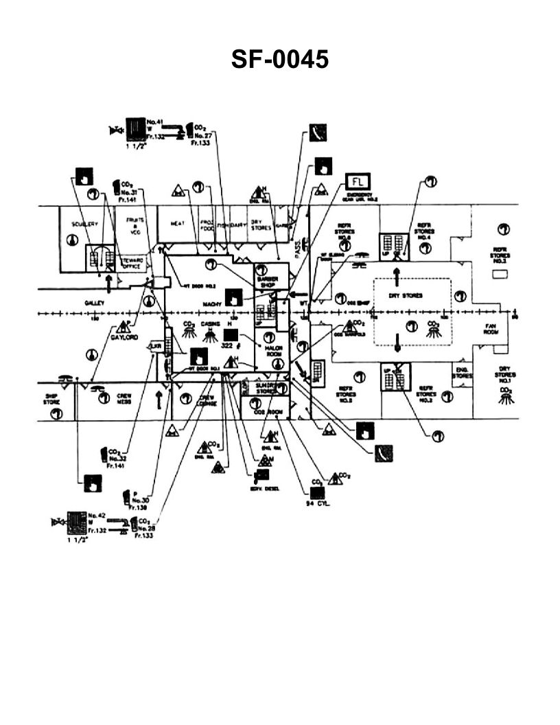
Question: You are part of a team to overhaul a fire that was just extinguished in the crew lounge. Where is the nearest fire axe to break apart the furniture? Illustration SF-0045
A. Starboard side, frame 132
B. Starboard side, frame 123
C. Midships, frame 123
D. Port side, frame 132
The correct answer is A) Starboard side, frame 132. The fire axe is typically located near the fire station or other emergency equipment, which is often situated along the starboard side of the vessel. Based on the illustration SF-0045, the fire axe would be located on the starboard side, frame 132, as this is a common placement to provide quick access in the event of an emergency. The other options are incorrect because the fire axe would not be located at midships (option C) or on the port side (option D) of the vessel, as these are not the standard locations for emergency equipment on a ship.
Question 341
Question: On the illustrated fire control plan, what emergency equipment is located in the scullery? Illustration SF-0045
A. Fixed water extinguishing system
B. Fire alarm pull-box
C. Gaylord system release valve
D. Heat detector
The correct answer is D) Heat detector. On a fire control plan, the heat detector is the emergency equipment typically located in the scullery, which is an area with increased fire risk due to the presence of cooking equipment and flammable materials. Heat detectors are designed to sense a rise in temperature and trigger an alarm, alerting the crew to a potential fire in the scullery. This allows for a rapid response to contain and extinguish the fire before it can spread. The other options are incorrect because: A) a fixed water extinguishing system would not be located in the scullery specifically, B) a fire alarm pull-box is a manual device typically located near exits, and C) a Gaylord system release valve is associated with the ventilation system, not the scullery.
Question 345
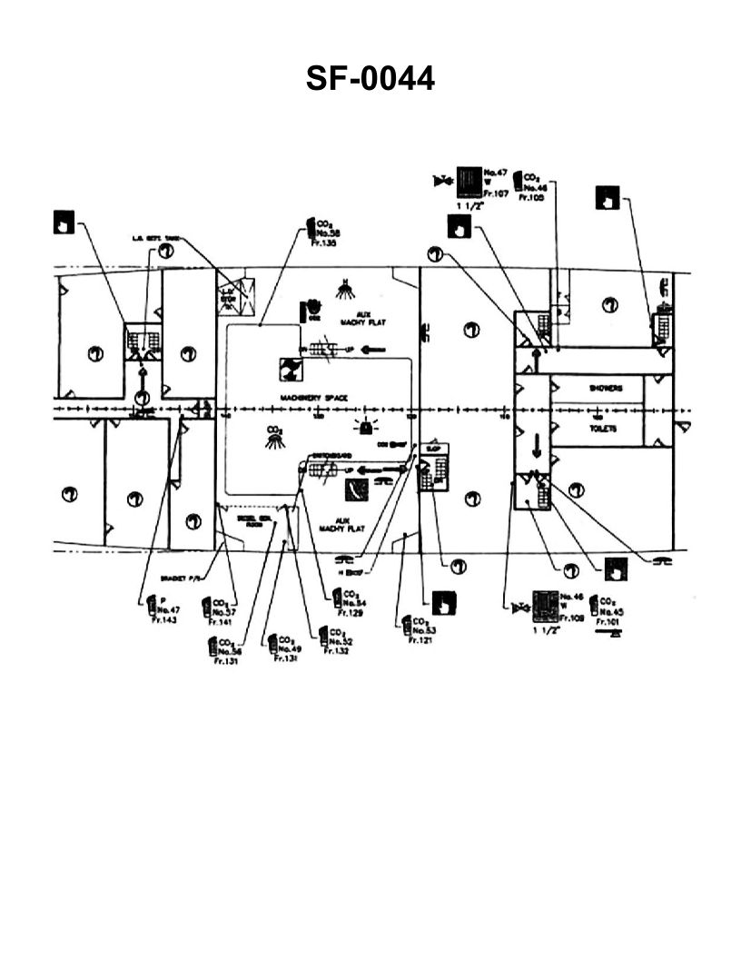
Question: You are being directed to a fire in the lower engine room, port side, frame 127. What machinery is found in that exact location? Illustration SF-0044
A. Lube oil purifier
B. Generator
C. Bilge pumps
D. Emergency fire pumps
The correct answer is C) Bilge pumps. The location specified in the question, frame 127 on the port side of the lower engine room, is typically where the bilge pumps would be found on a ship. Bilge pumps are essential for removing water that collects in the bilge, the lowest part of the ship's hull, and preventing the buildup of water that could compromise the vessel's stability and safety. This location is a common placement for bilge pumps to ensure they are readily accessible in the event of an emergency, such as a fire, when they may be needed to remove excess water. The other options, A) Lube oil purifier, B) Generator, and D) Emergency fire pumps, while important machinery, are not typically found at the specific location described in the question.