Pass Your Coast Guard Licensing Exams!
Study offline, track your progress, and simulate real exams with the Coast Guard Exams app
Steam Plants - 1st Asst/Chief
42 images
Question 2
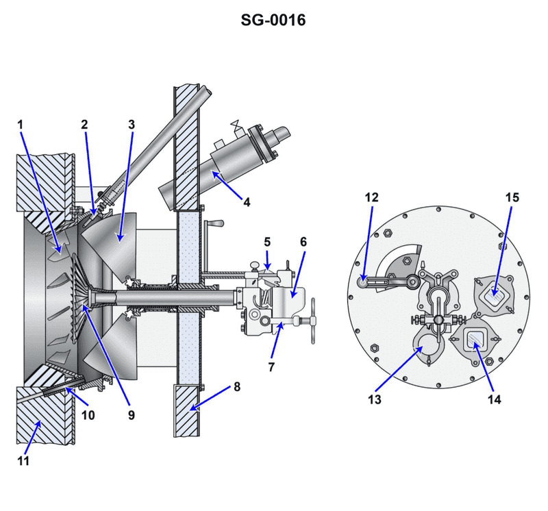
Question: According to the illustration, what part number identifies the "igniter"? Illustration SG-0016
A. 2
B. 3
C. 7
D. 9
A) 2 is the correct answer. The illustration SG-0016 clearly identifies part number 2 as the "igniter." This is the correct part number that corresponds to the igniter component in the diagram. The other answer choices are incorrect because they do not match the part number labeled as the igniter in the provided illustration. Part numbers 3, 7, and 9 are associated with different components shown in the diagram, but not the igniter specifically.
Question 3
Question: According to the illustration, what part number identifies the "air door handle"? Illustration SG-0016
A. 4
B. 6
C. 7
D. 12
The correct answer is D) 12. According to the illustration SG-0016, the "air door handle" is identified as part number 12. This can be clearly seen in the diagram, where the "air door handle" is labeled with the number 12. The other answer choices (A, B, and C) do not correspond to the "air door handle" in the illustration, and are therefore incorrect. Part numbers 4, 6, and 7 identify other components in the diagram, but not the specific "air door handle" that the question is asking about.
Question 4
Question: According to the illustration, what part number identifies the "diffuser"? Illustration SG-0016
A. 1
B. 3
C. 9
D. 7
The correct answer is C) 9. Based on the illustration SG-0016, the part number "9" identifies the "diffuser" component. This can be determined by directly referencing the labeled parts in the illustration, where part number 9 is specifically indicated as the "diffuser". The other answer choices are incorrect because they do not match the part number assigned to the diffuser in the provided illustration. Part numbers 1, 3, and 7 identify other components, but not the diffuser.
Question 20
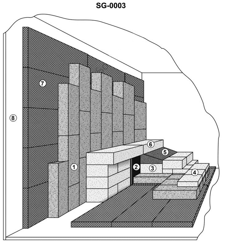
Question: According to the illustration of a typical boiler furnace rear wall, which item number would best represent "insulating block"? Illustration SG-0003
A. 3
B. 1
C. 2
D. 7
The correct answer is D. According to the illustration SG-0003, item number 7 represents the "insulating block" in the typical boiler furnace rear wall. Insulating blocks are used to line the interior of the furnace to provide thermal insulation and protect the outer walls from the high temperatures within the boiler. The other answer choices are incorrect because: A) Item 3 represents the "burner", which is a different component of the boiler furnace. B) Item 1 represents the "boiler shell", which is the outer casing of the boiler, not the insulating material. C) Item 2 represents the "refractory", which is a different type of insulating material used in the furnace.
Question 44
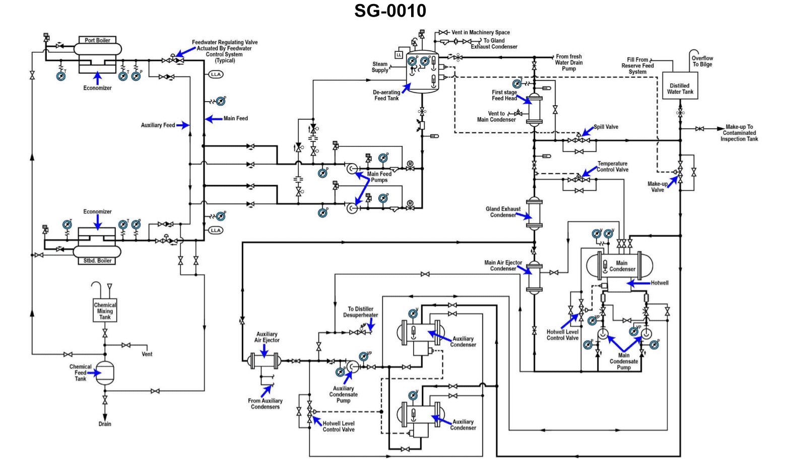
Question: Desecration of condensate primarily occurs in what section of the illustration shown? Illustration SG-0010
A. distilled water tank
B. main condenser hotwell
C. DFT
D. first stage feed heater
The correct answer is C) DFT (Diesel Fuel Tank). Desecration of condensate primarily occurs in the diesel fuel tank (DFT) section of the illustration SG-0010. This is because the diesel fuel tank is where contaminants and impurities can accumulate and compromise the quality of the condensate, leading to desecration. The other options, such as the distilled water tank, main condenser hotwell, and first stage feed heater, are not the primary locations where desecration of condensate occurs.
Question 48
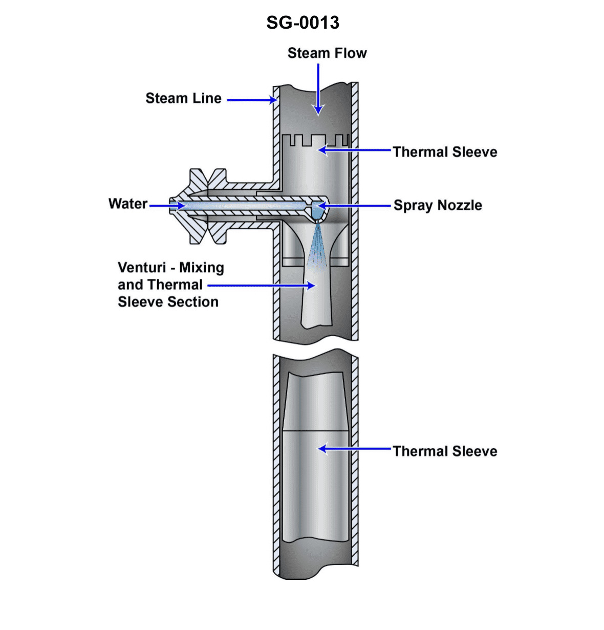
Question: The device shown in the illustration is a/an _______________. Illustration SG-0013
A. deaerator
B. desuperheater
C. eductor
D. air ejector
The correct answer is B) desuperheater. A desuperheater is a device used to reduce the temperature of superheated steam. The illustration SG-0013 shows a device that is consistent with the characteristics and function of a desuperheater. Desuperheaters are commonly used in steam-powered systems, such as those found on many commercial and military vessels, to control the temperature of the steam before it enters other components. The other options (deaerator, eductor, and air ejector) are not accurate descriptions of the device shown in the illustration, as they have different functions and designs that do not match the characteristics depicted.
Question 52
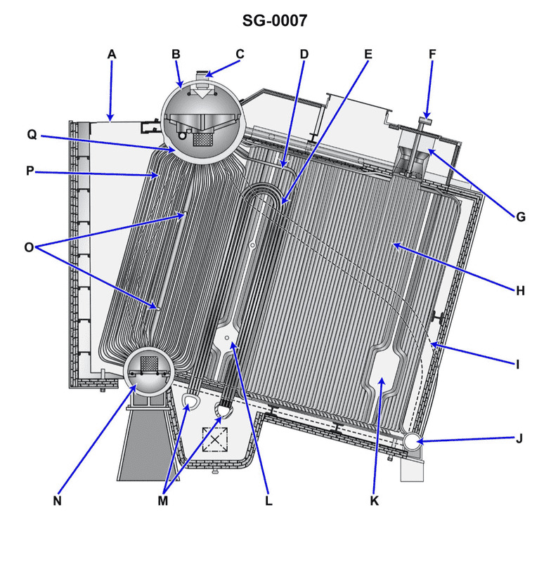
Question: The boiler wrapper sheet, shown in the illustration, is indicated by arrow _______________. Illustration SG-0007
A. A
B. B
C. H
D. I
The correct answer is B. The boiler wrapper sheet, which is the outer steel shell of the boiler, is indicated by arrow B in the illustration SG-0007. This is the component that contains the water and steam within the boiler system. The other answer choices are incorrect because: A) does not indicate the boiler wrapper sheet C) and D) refer to other components of the boiler system that are not the outer shell or wrapper sheet.
Question 93
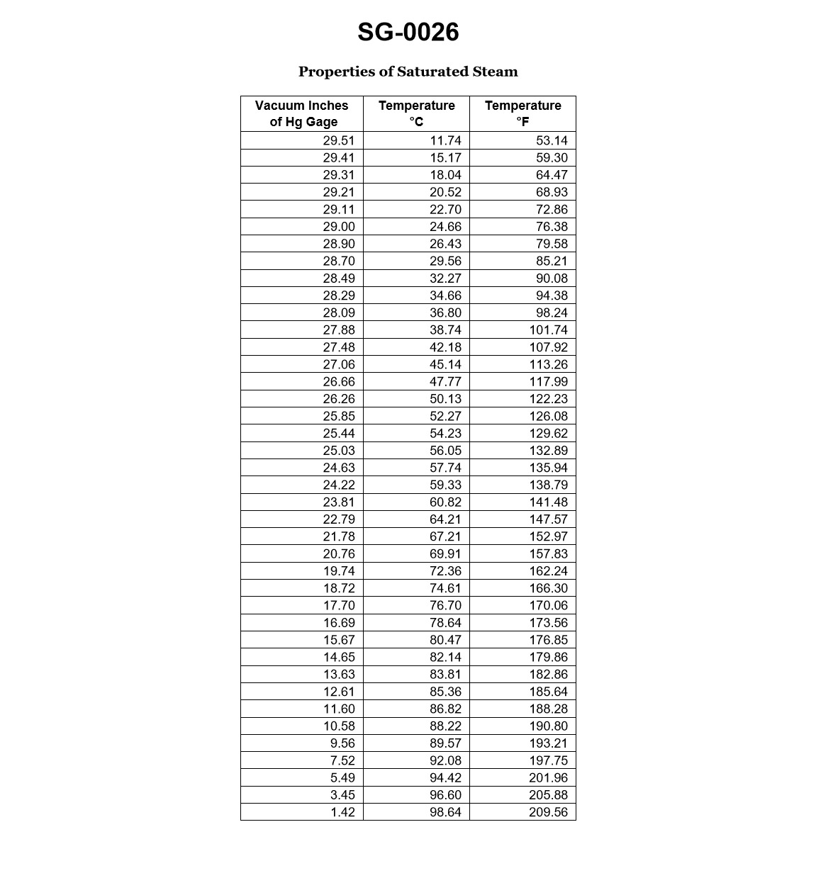
Question: If the main condenser were operating at a vacuum of 28.5"Hg, a condensate discharge temperature of 86°F, a seawater inlet temperature of 72°F, and a seawater outlet temperature of 79°F, what would be the condensate depression? Illustration SG-0026
A. 0.2 inches Hg
B. 0.7 inches Hg
C. 4 degrees Fahrenheit
D. 7 degrees Fahrenheit
The correct answer is C) 4 degrees Fahrenheit. The condensate depression is the difference between the condensate discharge temperature and the saturation temperature corresponding to the main condenser vacuum. With a vacuum of 28.5"Hg, the saturation temperature is approximately 86°F. Since the condensate discharge temperature is also 86°F, the condensate depression is 4 degrees Fahrenheit. The other options are incorrect because: A) 0.2 inches Hg is the incorrect unit for condensate depression, which is a temperature difference. B) 0.7 inches Hg is also the incorrect unit for condensate depression. D) 7 degrees Fahrenheit is an incorrect temperature difference based on the given information.
Question 108
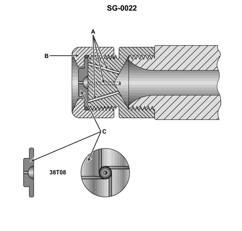
Question: The illustrated burner atomizer assembly is _______________. Illustration SG-0022
A. an example of a rotary cup type atomizer
B. used only for variable load steam atomization
C. used in a return flow type burner management system
D. straight mechanical
The correct answer is D) straight mechanical. The illustration SG-0022 depicts a simple, straight mechanical atomizer assembly, which is a common type of atomizer used in various burner systems. This type of atomizer relies on the mechanical force of the fuel pump to break the fuel into a fine mist, without the use of additional energy sources like rotary cups or steam. The other answer choices are incorrect because: A) a rotary cup type atomizer is a different design that uses a spinning cup to atomize the fuel; B) steam atomization is a distinct process not shown in the illustration; and C) a return flow type burner management system is a different configuration not depicted in the given illustration.
Question 110
Question: The boiler superheater shown in the illustration is a/an_______________. Illustration SG-0007
A. overdeck convection-type
B. overdeck integral-type
C. horizontal U-type
D. vertical U-type
The correct answer is D) vertical U-type. The illustration SG-0007 shows a vertical U-type boiler superheater, which is the correct design described in the answer choices. A vertical U-type superheater has the steam flow directed upwards through the first leg, then downwards through the second leg, forming a U-shape. This configuration allows for efficient heat transfer from the hot combustion gases to the steam flowing through the superheater tubes. The other options are incorrect because they do not accurately describe the design shown in the illustration. Option A refers to an overdeck convection-type superheater, which has a different configuration. Options B and C describe other types of superheater designs that are not represented in the given illustration.
Question 112
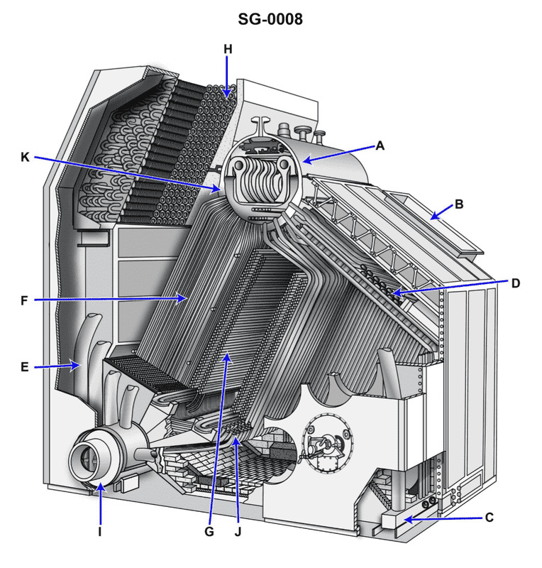
Question: Where is the superheater located in the boiler shown in the illustration? Illustration SG-0008
A. G
B. H
C. I
D. J
The correct answer is A. The superheater is located at position G in the illustration SG-0008. This is the correct answer based on the typical boiler design and configuration shown in the diagram. The superheater is a heat exchanger that increases the temperature of the steam exiting the boiler, improving the overall efficiency of the steam-generating system. The other options (H, I, and J) represent different components of the boiler, such as the steam drum, the mud drum, and the water column, but do not correspond to the location of the superheater in this particular illustration.
Question 114
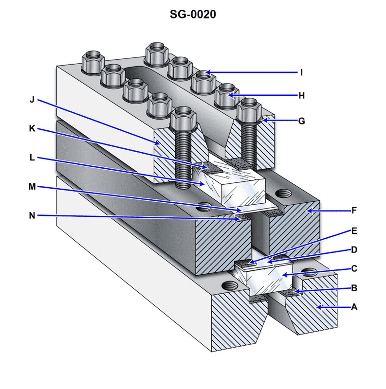
Question: The items labeled "D" and "M" as indicated on the illustration are commonly called _________________. Illustration SG-0020
A. mica sheets
B. glass inserts
C. cork gaskets
D. face plates
The correct answer is A) mica sheets. The items labeled "D" and "M" on the illustration SG-0020 are commonly referred to as mica sheets. Mica is a mineral that is used in electrical equipment due to its insulating properties. In the context of a US Coast Guard Captain's License Examination, mica sheets are often used as insulating materials in various electrical components. The other answer choices are incorrect because glass inserts, cork gaskets, and face plates are not the common terms used to describe the labeled items in the provided illustration.
Question 150
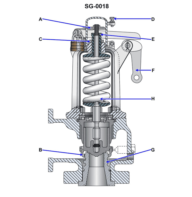
Question: Which of the listed types of safety valves is shown in the illustration? Illustration SG-0018
A. Huddling chamber type
B. Pressure-loaded type
C. Jet flow type
D. Nozzle reaction type
The correct answer is A) Huddling chamber type. The huddling chamber type of safety valve is shown in the illustration SG-0018. This type of valve uses a huddling chamber around the valve seat to create a pressure differential that helps the valve open quickly and fully when the set pressure is reached. This design is commonly used in marine and industrial applications to provide reliable overpressure protection. The other answer choices, such as pressure-loaded, jet flow, and nozzle reaction types, are different safety valve designs that have distinct operating principles and are not depicted in the given illustration.
Question 163
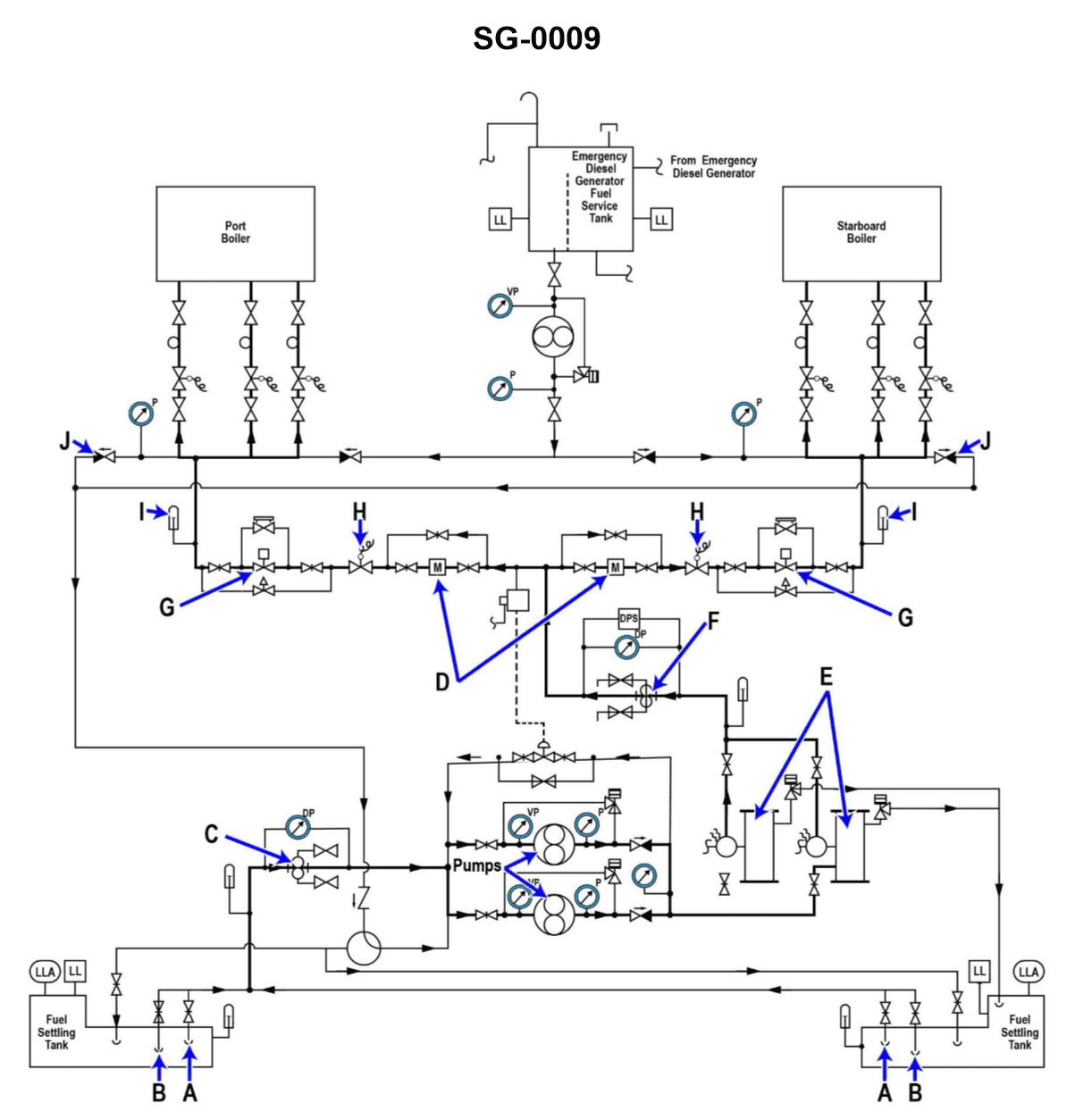
Question: Valve "H" shown in the illustration, functions to _______________. Illustration SG-0009
A. provide a quick shut off of fuel to the boiler
B. recirculate fuel oil during start-up
C. prevent a backflow from the manifold
D. regulate the amount of fuel burned
The correct answer is A) provide a quick shut off of fuel to the boiler. Valve "H" in the illustration functions as a quick shut-off valve for the fuel supply to the boiler. This is an important safety feature that allows the operator to immediately cut off the fuel flow in the event of an emergency or malfunction, preventing potential fires or explosions. The other answer choices are incorrect because: B) recirculating fuel oil is typically done during start-up, not the normal operation of the boiler; C) preventing backflow from the manifold is typically the function of a non-return or check valve; and D) regulating the amount of fuel burned is usually done by the main fuel control valve, not the valve labeled "H" in the illustration.
Question 210
Question: In the boiler shown in the illustration, the arrow "E" indicates a ________________. Illustration SG-0008
A. support tube
B. recirculating tube
C. downcomer
D. water wall tube
The correct answer is C) downcomer. In a boiler, the downcomer is a tube or pipe that carries the cooler, denser water from the steam drum to the bottom of the boiler, where it can be recirculated back up through the water walls or tubes to be heated and turned into steam. The arrow labeled "E" in the illustration SG-0008 is pointing to a downcomer, which is responsible for ensuring proper water circulation within the boiler. The other answer choices are incorrect because they do not accurately describe the component indicated by the arrow. A support tube is a structural element, a recirculating tube is used for water recirculation but not specifically a downcomer, and a water wall tube is part of the heating surface of the boiler, not the water circulation system.
Question 213
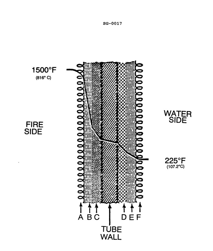
Question: Which area shown in the illustration will offer the most resistance to heat transfer from the fireside to the waterside of a boiler tube? Illustration SG-0017
A. E
B. B
C. C
D. D
The correct answer is B. The area labeled B in the illustration will offer the most resistance to heat transfer from the fireside to the waterside of a boiler tube. This is because the tube scale, which is a layer of deposits that forms on the inside of the boiler tube, acts as an insulator and inhibits the efficient transfer of heat from the fire to the water. The tube scale has a much lower thermal conductivity compared to the metal of the boiler tube, making it the area that presents the greatest resistance to heat transfer. The other options, A, C, and D, represent the metal of the boiler tube, the water, and the fire, respectively, which all have higher thermal conductivity and therefore offer less resistance to heat transfer compared to the tube scale.
Question 218
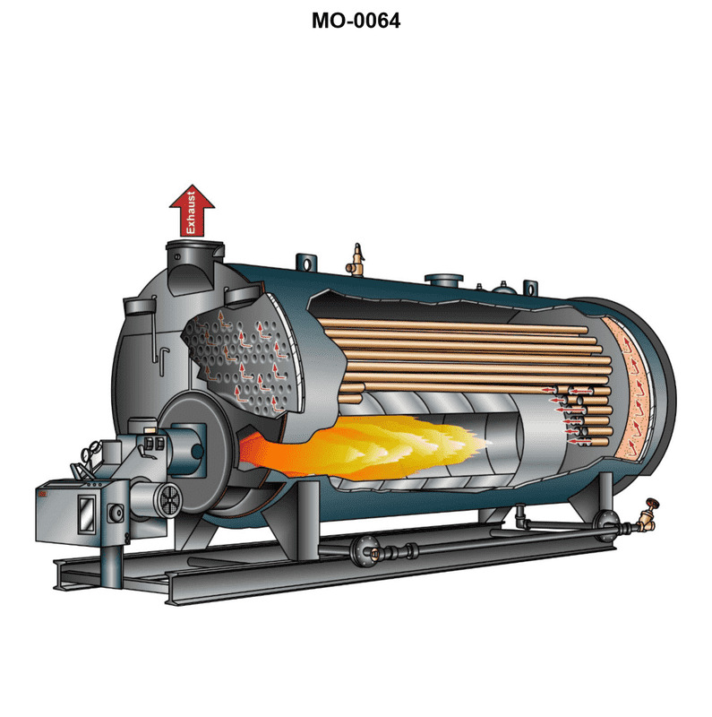
Question: The boiler shown in the illustration would be classed as MO-0064
A. two-pass, water-tube
B. two-pass, scotch marine
C. single-pass, fire-tube, scotch marine
D. forced circulation, coil-type
The correct answer is C) single-pass, fire-tube, scotch marine. The description of "single-pass, fire-tube, scotch marine" accurately matches the type of boiler shown in the illustration. A scotch marine boiler is a type of fire-tube boiler where the hot gases from the furnace pass through the boiler only once before exiting, making it a single-pass design. This type of boiler is commonly used on smaller vessels. The other answer choices do not fit the description of the boiler in the illustration. A two-pass, water-tube boiler, a two-pass, scotch marine boiler, and a forced circulation, coil-type boiler have different designs and characteristics that do not match the provided information.
Question 227
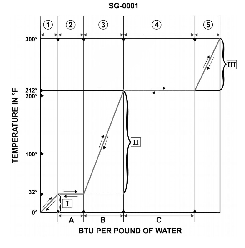
Question: If the saturation pressure of water is increased, the relative values shown on the illustrated graph of SG-0001 will change. According to pertinent information found in the steam tables of SG-0004, this will result in _ . Illustrations SG-0001 and SG-0004
A. no change to the length of line 4
B. a decrease in the length of line 4
C. no change in the height of line 4
D. a decrease in the height of line 4
The correct answer is B) a decrease in the length of line 4. When the saturation pressure of water is increased, the relative values shown on the illustrated graph of SG-0001 will change. According to the information found in the steam tables of SG-0004, an increase in saturation pressure will result in a decrease in the length of line 4, which represents the saturation line on the graph. The other options are incorrect because: A) there would be a change to the length of line 4, not no change; C) the height of line 4 would change, not remain constant; and D) the height of line 4 would decrease, not the length.
Question 228
Question: According to the data given in the illustration which of the following would be the physical state of the fluid at a gage vacuum of 25.03 inches Hg, and 126.08 degrees Fahrenheit? Illustration SG-0026
A. Superheated vapor.
B. Sub cooled liquid.
C. Mixture of saturated liquid and vapor.
D. Saturated liquid.
The correct answer is B) Sub cooled liquid. At a gage vacuum of 25.03 inches Hg and a temperature of 126.08 degrees Fahrenheit, the fluid would be in a sub cooled liquid state. This is because the given conditions place the fluid below the saturation curve on the pressure-temperature diagram, meaning the fluid is in a liquid state at a temperature lower than the saturation temperature for that pressure. The other answer choices are incorrect because: A) Superheated vapor requires the fluid to be above the saturation curve, C) Mixture of saturated liquid and vapor occurs at the saturation curve, and D) Saturated liquid occurs precisely at the saturation curve, not below it.
Question 230
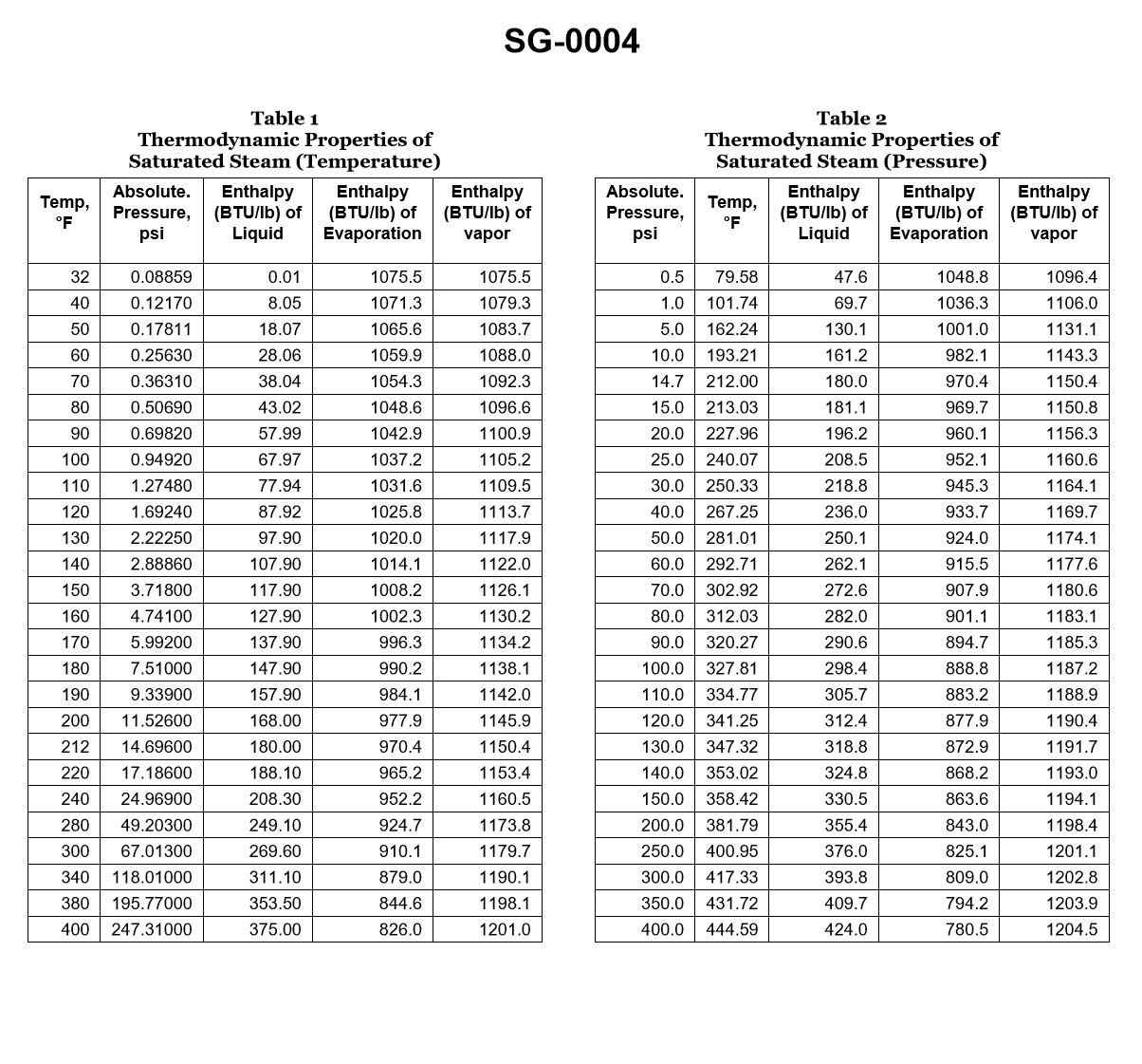
Question: Which of the following statements is true concerning the information tabulated in the table? Illustration SG-0004
A. At 185.3 psig
B. 192°C).
C. When one pound of water changes to one pound of steam at 200 psia
D. C
The correct answer is C) When one pound of water changes to one pound of steam at 200 psia. The information provided in the table illustrates the changes in temperature and pressure when one pound of water changes to one pound of steam. The correct answer, C, specifically refers to this process occurring at 200 psia (pounds per square inch absolute), which is the standard unit of measurement for pressure in steam systems. The other options are incorrect because they do not accurately describe the information shown in the table. Option A refers to a specific pressure value that is not mentioned, and option B refers to a temperature value in Celsius, which is also not provided in the table.
Question 231
Question: If a boiler generates saturated steam at 125.3 psig, how much heat is required to change the water into steam if the feed water temperature is 240°F? Illustration SG-0004
A. 30.5 Btu/lb
B. 116.5 Btu/lb
C. 582.7 Btu/lb
D. 983.4 Btu/lb
The correct answer is D) 983.4 Btu/lb. The amount of heat required to change water into saturated steam at a given pressure is known as the latent heat of vaporization. At a pressure of 125.3 psig, the latent heat of vaporization for water is 983.4 Btu/lb. This value can be found in steam tables or other reference materials commonly used for marine engineering calculations. The other options are incorrect because they do not represent the correct latent heat of vaporization for the given pressure. Option A (30.5 Btu/lb) is too low, Option B (116.5 Btu/lb) is also too low, and Option C (582.7 Btu/lb) is significantly lower than the actual value.
Question 244
Question: Which piping system is described in the illustration provided. Illustration SG-0010
A. Auxiliary desuperheated steam system
B. Boiler feed and condensate system
C. Main superheated steam system
D. Turbine bleed steam system
The correct answer is B) Boiler feed and condensate system. The boiler feed and condensate system is responsible for circulating water through the boiler and returning the condensed steam back to the boiler. This closed-loop system ensures a continuous supply of water to the boiler, which is essential for the proper operation of the steam plant. The illustration SG-0010 depicts the components and piping associated with this critical system. The other options are incorrect because they describe different steam systems that are not shown in the provided illustration. The auxiliary desuperheated steam system, main superheated steam system, and turbine bleed steam system are not the focus of this particular illustration.
Question 285
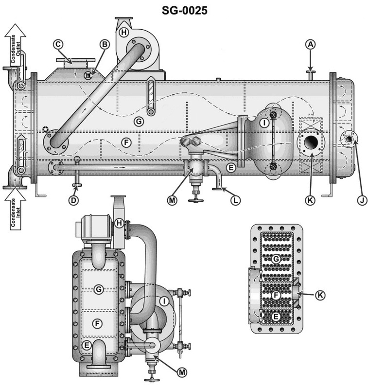
Question: The unit shown in the illustration is used as the _______________ Illustration SG-0025
A. Butterworth feed heater
B. combined low pressure feed heater
C. flash evaporator salt water feed heater
D. high pressure feed heater
The correct answer is B) combined low pressure feed heater. The illustration SG-0025 depicts a combined low pressure feed heater, which is a common component in marine steam propulsion systems. This type of heater is used to increase the temperature of the boiler feedwater by utilizing the thermal energy from the main steam system, thereby improving the overall efficiency of the steam plant. The other options are incorrect because: A) a Butterworth feed heater is used for cleaning the feedwater system, C) a flash evaporator salt water feed heater is used to desalinate seawater for boiler makeup, and D) a high pressure feed heater is a different component in the steam system, typically located upstream of the boiler.
Question 286
Question: The connections labeled "A" in the illustration, are used to _ SG-0025
A. provide a point of admission for the L.P. bleed steam
B. drain condensate from the feed water heater to the main condenser
C. maintain a vacuum in the shell of the feed water heater
D. provide a point of admission for the steam air heater drains
The correct answer is C) maintain a vacuum in the shell of the feed water heater. The connections labeled "A" in the illustration are used to maintain a vacuum in the shell of the feed water heater. This is necessary to improve the efficiency of the heat transfer process and prevent condensation issues. Maintaining a vacuum helps draw the steam through the feed water heater, allowing it to effectively heat the feed water before it enters the boiler. The other answer choices are incorrect because they do not accurately describe the purpose of the "A" connections in the context of a feed water heater system. Option A relates to the LP (low pressure) bleed steam, option B describes draining condensate, and option D is about admitting steam air heater drains, none of which are the primary function of the "A" connections as described in the question.
Question 288
Question: The steam separator as used in conjunction with a steam whistle normally drains to which of the listed drain systems?
A. Low pressure
B. High pressure
C. Contaminated
D. Main turbine
The correct answer is B) High pressure. The steam separator is used to remove moisture from the steam before it reaches the steam whistle. This is important to ensure the whistle operates properly. The steam separator drains to the high-pressure drain system, which is designed to handle the high-pressure condensate from the steam system. The other options are incorrect because: A) Low pressure drain systems are typically used for lower-pressure systems, not the high-pressure steam whistle. C) Contaminated drain systems are used for waste streams, not the steam separator. D) The main turbine is not involved in the steam whistle system.
Question 296
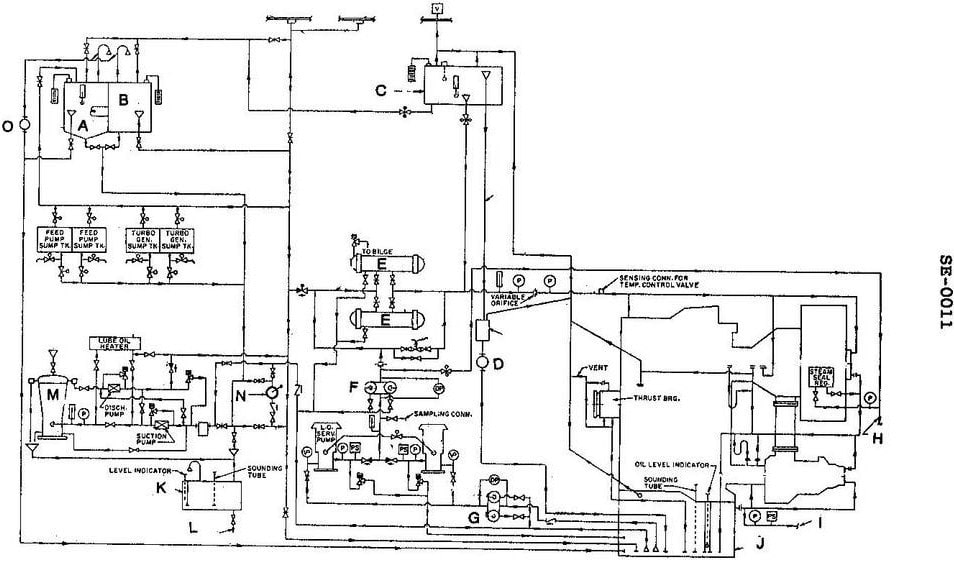
Question: Which of the following statements is true concerning the lube oil system shown in the illustration? Illustration SE-0011
A. The drains from lube oil coolers can be directed back to the main sump, the sludge tank or the lube oil purifier.
B. The gravity tank overflow line leads directly to the lube oil sludge tank.
C. The gravity tank directly provides the normal supply of oil to the turbines and gears.
D. The three-way temperature control valve bypasses cooling water around or through the lubricating oil cooler to maintain the desired oil temperature.
The correct answer is A) The drains from lube oil coolers can be directed back to the main sump, the sludge tank or the lube oil purifier. This is the correct answer because the lube oil system is designed to recirculate and reuse the lubricating oil, and the drains from the coolers allow the oil to be routed back to the main sump, sludge tank, or purifier for cleaning and reuse. The other options are incorrect because: B) the gravity tank overflow does not directly go to the sludge tank, C) the gravity tank does not directly supply the turbines and gears, and D) the temperature control valve regulates the cooling water flow to maintain the desired oil temperature, not bypass the cooler entirely.
Question 301
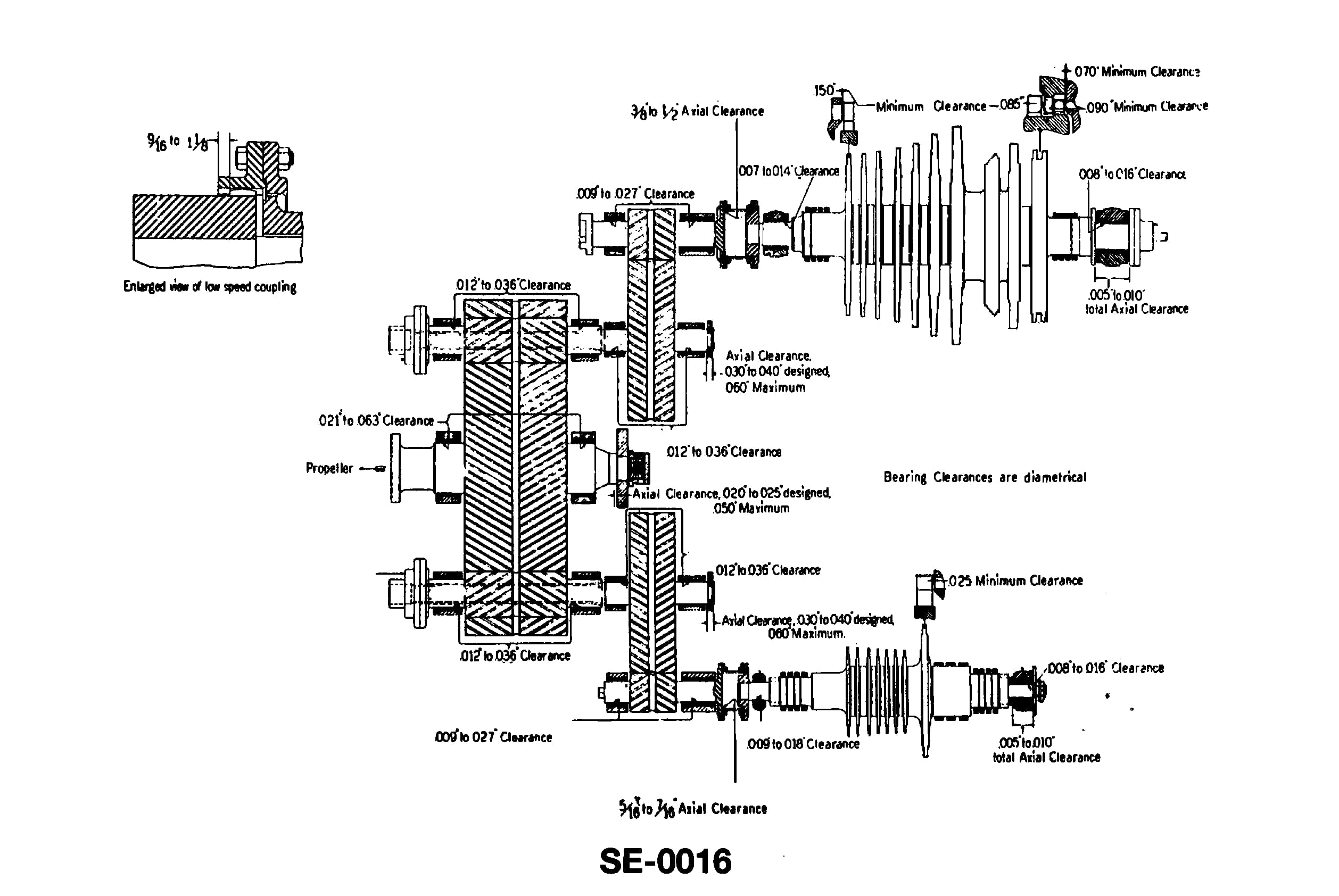
Question: Which of the following statements is true concerning the turbine shown in the illustration? Illustration SE-0016
A. A steam deflector is provided between the astern element and the ahead stages of the LP turbine.
B. The ahead rotor can be classified as a helical flow, Parsons type turbine.
C. The astern element is of the Curtis type consisting of two three-row stages.
D. The low-pressure turbine is designed with reaction type stages.
The correct answer is A) A steam deflector is provided between the astern element and the ahead stages of the LP turbine. This is correct because the illustration shows a typical marine steam turbine design, where a steam deflector is commonly used to direct the steam flow from the astern element to the ahead stages of the low-pressure (LP) turbine. This arrangement helps to improve the efficiency of the turbine by minimizing losses during the transition from astern to ahead operation. The other answer choices are incorrect because: B) The ahead rotor is more likely a reaction type turbine, not a Parsons type; C) The astern element is typically a single-stage Curtis type, not two three-row stages; and D) The LP turbine is indeed designed with reaction type stages, not the statement in the question.
Question 311
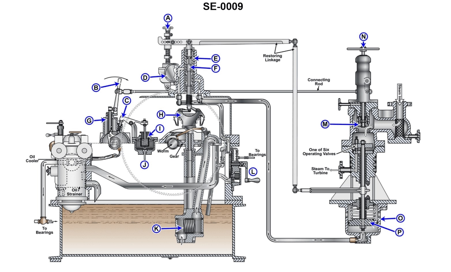
Question: A motor driven synchronizing device, figure "D" shown in the illustration, operated from the generator switchboard, initiates fine adjustments to the steam turbine speed by directly _______________. Illustration SE-0009
A. varying the pivot rod stroke length on the governor weight eccentric pad
B. increasing or decreasing operating spring pressure
C. changing the vertical location of the pilot valve bushing
D. raising or lowering the nozzle block lifting beam
The correct answer is C) changing the vertical location of the pilot valve bushing. The synchronizing device, labeled as figure "D" in the illustration, is responsible for making fine adjustments to the steam turbine speed. By changing the vertical location of the pilot valve bushing, the synchronizing device can effectively adjust the steam flow to the turbine, allowing for precise speed control. The other options are incorrect because they do not directly impact the steam flow to the turbine. Varying the pivot rod stroke length (A), increasing/decreasing spring pressure (B), or raising/lowering the nozzle block lifting beam (D) are not the primary mechanisms used by the synchronizing device to make the necessary fine adjustments to the turbine speed.
Question 314
Question: Which of the listed parts illustrated in the turbo-generator governing system, provides the follow-up to prevent the nozzle valves from cycling between the fully open and fully closed positions, with each variation in turbine speed? Illustration SE-0009
A. D
B. E
C. H
D. O
The correct answer is B) E. The follow-up mechanism in the turbo-generator governing system, which prevents the nozzle valves from cycling between the fully open and fully closed positions with each variation in turbine speed, is the speed error feedback device (labeled E in the illustration SE-0009). This feedback device senses the generator speed and provides a corresponding electrical signal to the speed governor (labeled D), which in turn adjusts the nozzle valve position to maintain a stable, steady speed. The other options (A, C, and D) do not directly perform this follow-up function to prevent rapid valve cycling.
Question 315
Question: Which of the listed actions will occur when there is an increase in load on a ship service generator equipped with a centrifugal type hydraulic governor? Illustration SE-0009
A. The governor weights move outward.
B. More oil will enter the operating cylinder (O).
C. Steam flow to the turbine decreases.
D. The operating piston is forced to move lower.
The correct answer is B) More oil will enter the operating cylinder (O). When there is an increase in load on a ship service generator equipped with a centrifugal type hydraulic governor, the governor weights will move outward due to the increased centrifugal force. This causes the operating piston to move upward, which in turn allows more oil to enter the operating cylinder (O). This increased oil flow helps to maintain the generator's speed and compensate for the increased load. The other options are incorrect because: A) The governor weights moving outward is the cause of the increased oil flow, not the result. C) Steam flow is not relevant in this case, as this is a ship service generator, not a steam turbine. D) The operating piston moves upward, not lower, in response to the increased load.
Question 341
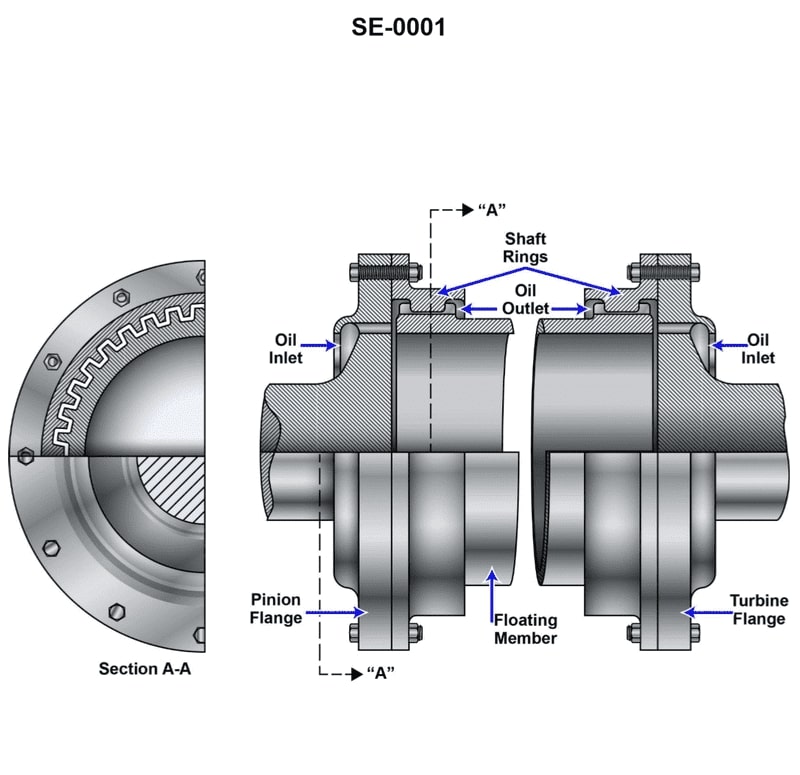
Question: The part shown in the illustration would be located between which of the following components of a modern geared turbine main propulsion unit? Illustration SE-0001
A. Between the bull gear and line shaft on the thrust bearing side of the gear.
B. Between the first reduction gears and high-speed pinions of the high pressure and low pressure turbines.
C. Between the bull gear and line shaft on the side of the gear opposite the thrust bearing.
D. Between the rotors and high-speed pinions of the high pressure and low pressure turbines.
The correct answer is D) Between the rotors and high-speed pinions of the high pressure and low pressure turbines. The part shown in the illustration would be located between the rotors and high-speed pinions of the high pressure and low pressure turbines in a modern geared turbine main propulsion unit. This is the correct location because the illustration depicts a coupling or shaft that connects the turbine rotors to the high-speed pinions, which then engage the reduction gears to power the propeller. The other answer choices are incorrect because they do not accurately describe the location of the part shown in the illustration within the turbine propulsion system. Options A, B, and C refer to different components and connections that are not depicted in the provided illustration.
Question 342
Question: Which of the following statements is true concerning the coupling shown in the illustration? Illustration SE-0001
A. It can be used to connect the main turbine to the high-speed pinion.
B. It is commonly used between the first reduction pinion and the second reduction gear.
C. It is suitable for use on small auxiliary turbines only.
D. It allows for any misalignment between the main turbine and the second reduction gear.
The correct answer is A) It can be used to connect the main turbine to the high-speed pinion. This type of coupling, known as a flexible coupling, is commonly used to connect the main turbine to the high-speed pinion in marine propulsion systems. Flexible couplings are designed to accommodate minor misalignment and vibrations between the turbine and the gearbox, allowing for a smooth transfer of power. The other options are incorrect because: B) This type of coupling is not typically used between the first and second reduction gears, which often use a more rigid connection. C) Flexible couplings are not limited to small auxiliary turbines - they are widely used in larger main propulsion systems as well. D) While flexible couplings can accommodate some misalignment, their primary purpose is to connect the turbine to the high-speed pinion, not to allow for significant misalignment between the turbine and the second reduction gear.
Question 352
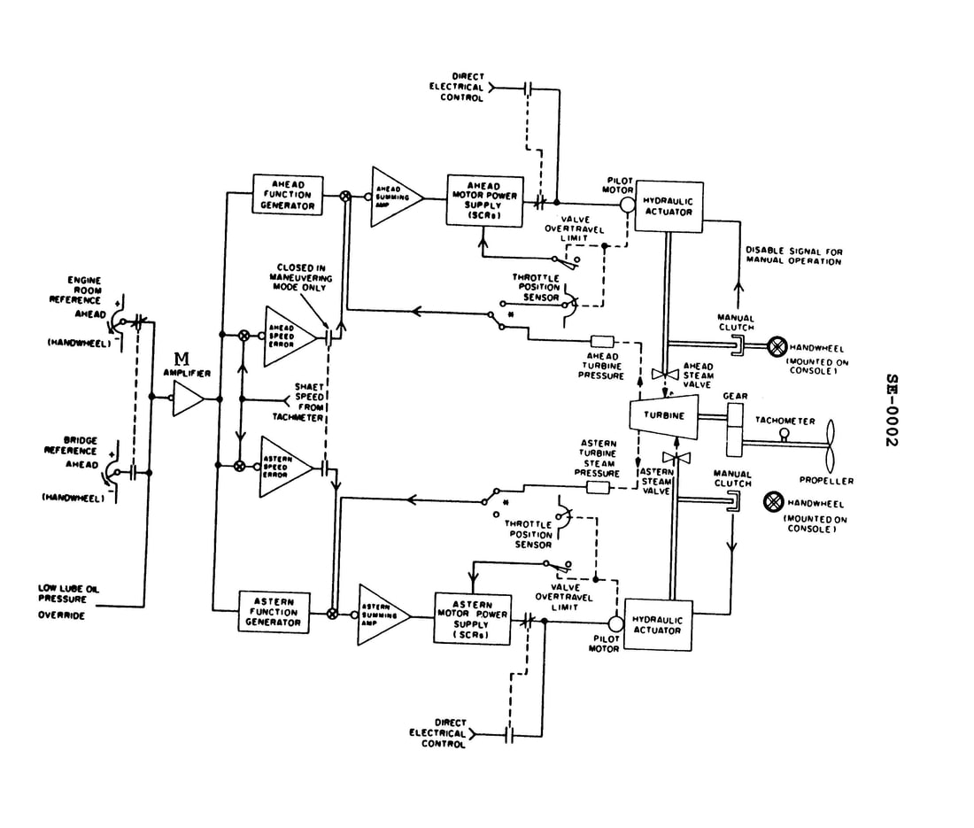
Question: In the illustration, the function generators will accept only a signal of a given polarity and the amplifier "M" inverts the polarity of the signal. If negative is used for the ahead and positive for the astern reference potentiometers, moving the bridge reference potentiometer in the direction indicated will have what effect while the system is operating in the mode selected for in the illustration? Illustration SE-0002
A. A positive signal will be processed by the ahead function generator to open the ahead steam valve wider.
B. No signal will be processed because the engine room is currently selected to have control.
C. A negative signal will be processed by the ahead function generator to open the ahead steam valve wider.
D. A positive signal will be processed by the astern function generator to open the astern steam valve wider.
The correct answer is B) No signal will be processed because the engine room is currently selected to have control. In the given illustration, the function generators are designed to accept only a signal of a given polarity. The amplifier "M" inverts the polarity of the signal. If the ahead reference potentiometer uses a negative signal and the astern reference potentiometer uses a positive signal, moving the bridge reference potentiometer in the indicated direction would result in a signal that is not compatible with the function generators. Since the system is operating in the mode selected for in the illustration, the engine room is currently in control. Therefore, no signal from the bridge reference potentiometer will be processed, as the engine room has the control authority in this mode of operation.
Question 353
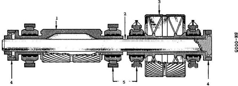
Question: Which of the statements listed applies to the quill shaft shown in the illustration? Illustration SE-0005
A. It provides torsional rigidity to help maintain alignment between gear train and the turbine rotor.
B. It absorbs the axial thrust generated by the meshing gears.
C. It permits axial movement between the high speed gear and low speed pinion.
D. It compensates for high speed pinion radial misalignment.
The correct answer is C) It permits axial movement between the high speed gear and low speed pinion. The quill shaft allows for axial movement between the high speed gear and low speed pinion, which is necessary to accommodate thermal expansion and other dimensional changes that can occur during turbine operation. This axial movement helps maintain proper gear alignment and engagement, preventing damage to the gear teeth. The other answer choices are incorrect because: A) The quill shaft does not provide torsional rigidity, but rather allows for controlled axial movement. B) The quill shaft does not absorb axial thrust, which is typically handled by other components in the gear train. D) The quill shaft does not compensate for radial misalignment, but rather allows for controlled axial movement.
Question 354
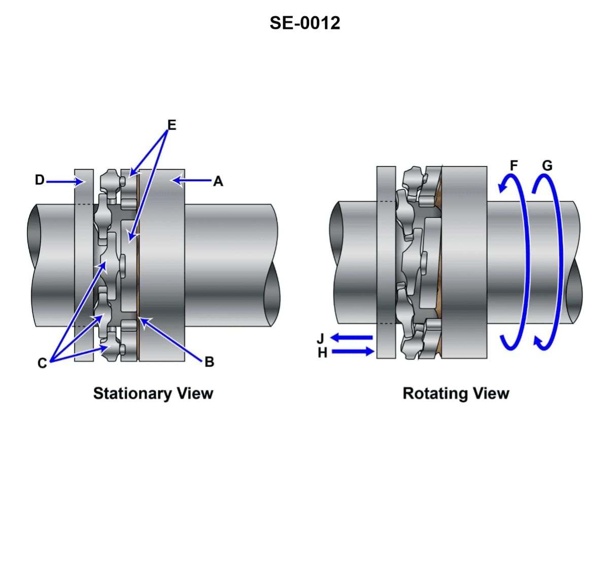
Question: The base ring shown in the illustration is identified by the letter _______________. Illustration SE-0012
A. A
B. E
C. C
D. D
The correct answer is D. The base ring shown in the illustration SE-0012 is identified by the letter D. This is based on the standard conventions used in navigation and seamanship illustrations, where specific components of a diagram or image are labeled using letters to aid in identification and reference. The other answer choices are incorrect because A, E, and C do not correspond to the base ring element in the provided illustration. The labeling follows a clear and established system, and D is the appropriate letter designating the base ring in this specific diagram.
Question 355
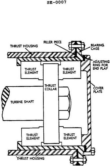
Question: In the thrust bearing assembly illustrated the total oil clearance can be correctly decreased by _______________. Illustration SE-0007
A. decreasing the thickness of the adjusting ring
B. increasing the thickness of the adjusting ring
C. increasing the thickness of the filler piece
D. decreasing the thickness of the filler piece
The correct answer is A) decreasing the thickness of the adjusting ring. The total oil clearance in the thrust bearing assembly can be decreased by decreasing the thickness of the adjusting ring. This is because the adjusting ring is used to set the clearance between the thrust collar and the thrust bearing. Reducing the thickness of the adjusting ring will bring the thrust collar and bearing closer together, thus decreasing the total oil clearance. The other options are incorrect because increasing the thickness of the adjusting ring or the filler piece would increase the clearance, and decreasing the thickness of the filler piece would not directly affect the clearance between the thrust collar and bearing.
Question 356
Question: In the diagrammatic arrangement of the thrust bearing, shown in the illustration, the direction of shaft rotation and the direction of thrust are indicated respectively by arrows _______________. Illustration SE-0012
A. G and J
B. F and J
C. F and H
D. G and H
The correct answer is B) F and J. The direction of shaft rotation and the direction of thrust are indicated by the arrows in the illustration. Arrow F indicates the direction of shaft rotation, while arrow J indicates the direction of thrust. The other options are incorrect because: A) G and J are not the correct arrows indicating the direction of shaft rotation and thrust, respectively. C) F and H are not the correct arrows indicating the direction of shaft rotation and thrust, respectively. D) G and H are not the correct arrows indicating the direction of shaft rotation and thrust, respectively.
Question 361
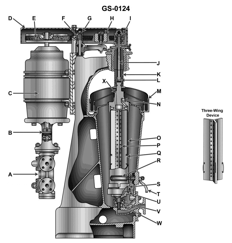
Question: The three wing device in the unit illustrated is maintained in its position by item _______________. Illustration GS-0124
A. O
B. P
C. Q
D. R
The correct answer is C) Q. The three-wing device in the illustration GS-0124 is maintained in its position by the item labeled Q, which is likely a retaining ring or fastener that secures the device in place. This is in accordance with the design and construction requirements for navigational equipment and devices used on US Coast Guard-inspected vessels. The other answer choices are incorrect because they do not correspond to the component responsible for maintaining the position of the three-wing device based on the information provided in the illustration.
Question 364
Question: Water removed through centrifugal force in the illustrated unit is displaced from the bowl through _______________. Illustration GS-0124
A. K
B. N
C. V
D. X
The correct answer is B) N. The water removed through centrifugal force in the illustrated unit is displaced from the bowl through the discharge nozzle, which is represented by the letter "N" in the illustration. The centrifugal force created by the spinning motion of the bowl separates the water from the heavier solids, and the water is then forced out through the discharge nozzle (N) while the solids remain in the bowl. The other answer choices (A, C, and D) do not correspond to the components shown in the illustration that are responsible for the discharge of the water separated by centrifugal force.
Question 372
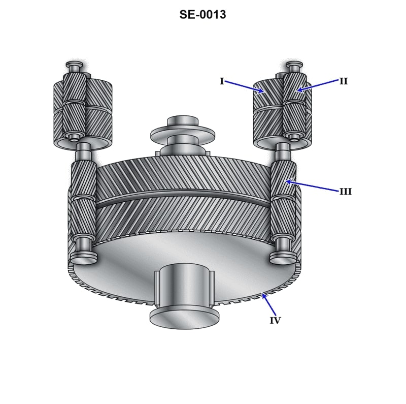
Question: The reduction gear shown in the illustration is a/an _______________. Illustration SE-0013
A. locked-train double reduction gear
B. articulated double reduction gear
C. nested double reduction gear
D. nested four-step reduction gear
The correct answer is B) articulated double reduction gear. The illustration SE-0013 depicts an articulated double reduction gear, which is a type of reduction gear commonly used in marine propulsion systems. This gear consists of two reduction stages, where the input power is reduced in two steps to match the optimal rotational speed of the propeller. The other options are incorrect because: A) A locked-train double reduction gear refers to a different type of reduction gear that does not have the articulated design shown in the illustration. C) A nested double reduction gear has a different internal arrangement compared to the articulated design. D) A nested four-step reduction gear has an additional reduction stage, which is not the case in the provided illustration.
Question 376
Question: The component labeled "II", as shown in the illustration is called the _______________. Illustration SE-0013
A. first reduction gear
B. second reduction pinion
C. second reduction gear
D. high-speed pinion
The correct answer is D) high-speed pinion. The high-speed pinion (labeled "II" in the illustration) is the smaller gear that meshes with the larger second reduction gear, which is the component that transfers power from the engine to the propeller shaft. This high-speed pinion is a critical part of the marine propulsion system, as it helps to step down the engine's high rotational speed to a lower speed more suitable for propelling the vessel. The other answer choices are incorrect because they do not accurately describe the component labeled "II" in the illustration. The first reduction gear, second reduction pinion, and second reduction gear are different components within the marine propulsion system, but they are not the specific component shown as "II" in this particular illustration.
Question 405
Question: In the illustrated device, what would be a reason for oil being discharged from port "N"? Illustration GS-0124
A. This would be normal for the operation.
B. The device being operated as a clarifier.
C. The ring dam size is too small.
D. The ring dam size is too large.
The correct answer is D) The ring dam size is too large. In the illustrated device, if oil is being discharged from port "N", it likely indicates that the ring dam size is too large. This would allow the oil to overflow the ring dam and be discharged, which is not the normal operation. The purpose of the ring dam is to contain the oil and prevent it from being discharged overboard. If the ring dam is too large, it cannot effectively contain the oil, leading to the observed oil discharge. The other options are incorrect because A) normal operation would not involve oil discharge, B) the device is not functioning as a clarifier, and C) a ring dam that is too small would more likely lead to oil spilling over the sides, not through port "N".