Question 113Electricity & Electronics - Assistant Engineer
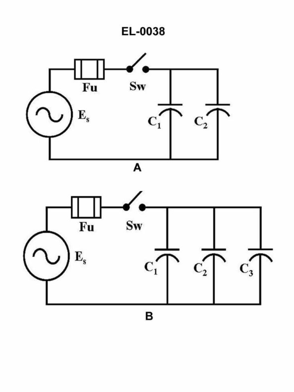
70% to passWhat would be the capacitive reactance of the circuit shown in figure "A" of the illustration if the capacitance of C1 was 100 microfarads, the capacitance of C2 was 200 microfarads and the frequency of the source was 60 cycles per second (Hz)? Illustration EL-0038
A8.8 ohms
B17.7 ohms
C39.8 ohms
D79.6 ohms
AI Explanation
The correct answer is A) 8.8 ohms. The capacitive reactance (Xc) of a circuit is calculated using the formula Xc = 1 / (2πfC), where f is the frequency of the source and C is the capacitance. In this case, the frequency is 60 Hz, and the capacitances are 100 microfarads (0.0001 farads) for C1 and 200 microfarads (0.0002 farads) for C2. Plugging these values into the formula, we get Xc1 = 1 / (2π * 60 * 0.0001) = 26.5 ohms for C1, and Xc2 = 1 / (2π * 60 * 0.0002) = 13.3 ohms for C2. The total capacitive reactance of the circuit is the parallel combination of these two reactances, which is 8.8 ohms.
Related Questions
Q52:Before electrical work can be safely undertaken, the equipment must be de-energi...
Q64:Which of the following figures shown in the illustration represents incandescent...
Q99:Assuming that the electrolyte has had sufficient time to be uniformly diffused t...
Q412:If a DC motor has its armature and field connected across a resistor when the mo...
Q517:Some shipboard high voltage systems have the neutral point of the generators bon...
Ready to test your knowledge?
Take a Electricity & Electronics - Assistant Engineer Practice ExamOfficial Resources
Pass Your Coast Guard Licensing Exams!
Study offline, track your progress, and simulate real exams with the Coast Guard Exams app