Question 119Electricity & Electronics - Assistant Engineer
70% to passWhat statement is true concerning the electrical diagram shown in figure "B" of the illustration? Illustration EL-0019
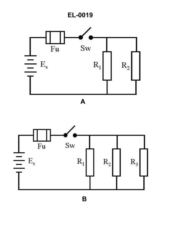
AThe voltages measured across 'R1', 'R2' and 'R3' will be different if 'R1', 'R2' and 'R3' have different values.
BThe total resistance equals R1 + R2 + R3.
C'R1', 'R2', and 'R3' are connected in parallel.
D'R1', 'R2', and 'R3' are connected in series.
AI Explanation
The correct answer is C) 'R1', 'R2', and 'R3' are connected in parallel. The key to identifying this is that the voltages measured across 'R1', 'R2', and 'R3' will be the same if they have different values. This indicates a parallel circuit configuration, where the voltage is the same across all the resistors. In a series circuit, the voltages across each resistor would be different. The other options are incorrect because B) is only true for series circuits, and A) and D) are not consistent with the given information about the voltages being the same across the resistors.
Related Questions
Q445:DC propulsion motor brush pressure depends on the brush grade used. In practice ...
Q249:In figure "1" of the diagram shown in the illustration, the three phase step-dow...
Q81:When a compound wound DC motor is differentially compounded, what does this mean...
Q532:What would be the synchronous speed of an eight-pole three-phase squirrel-cage i...
Q299:In referring to the illustration of the Ward-Leonard drive system, what type of ...
Ready to test your knowledge?
Take a Electricity & Electronics - Assistant Engineer Practice ExamOfficial Resources
Pass Your Coast Guard Licensing Exams!
Study offline, track your progress, and simulate real exams with the Coast Guard Exams app