Question 354Electricity & Electronics - Assistant Engineer
70% to passReferring to figure "2" of the illustration, if the inputs at A and B are both "0", what will be the outputs at "C", "D", "E", and "F" respectively? Illustration EL-0089
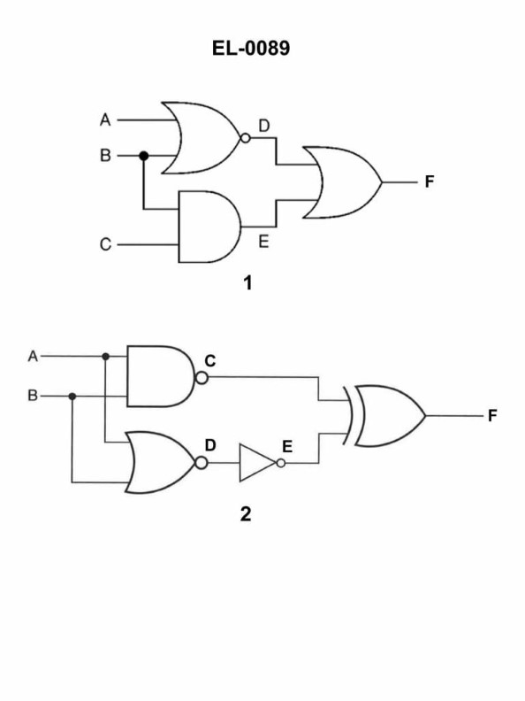
AC = 1 D = 1 E = 1 F = 1
BC = 0 D = 1 E = 0 F = 1
CC = 1 D = 0 E = 0 F = 1
DC = 1 D = 1 E = 0 F = 1
AI Explanation
The correct answer is D) C = 1 D = 1 E = 0 F = 1. The reasoning is based on the logic gates illustrated in figure "2". When both inputs A and B are "0", the AND gate will output a "0" at E, while the OR gate will output a "1" at C, D, and F. This logic operation is consistent with the truth table for AND and OR gates, making D the correct answer. The other options are incorrect because they do not accurately represent the logic gate outputs given the input conditions specified in the question.
Related Questions
Q512:When completing repairs on a high voltage circuit where portable grounding strap...
Q167:Which of the illustrated motors has an open, drip-proof (ODP) motor enclosure? ...
Q310:Suppose it is desired to connect a dual voltage three phase squirrel-cage induct...
Q576:If the cooling water system is isolated for repairs, but it is still desirable t...
Q204:To facilitate communication between the wheelhouse and the steering gear room in...
Ready to test your knowledge?
Take a Electricity & Electronics - Assistant Engineer Practice ExamOfficial Resources
Pass Your Coast Guard Licensing Exams!
Study offline, track your progress, and simulate real exams with the Coast Guard Exams app