Question 360Electricity & Electronics - Assistant Engineer
70% to passReferring to figure "4" of the illustration, what type of logic gate is symbolized? Illustration EL-0035
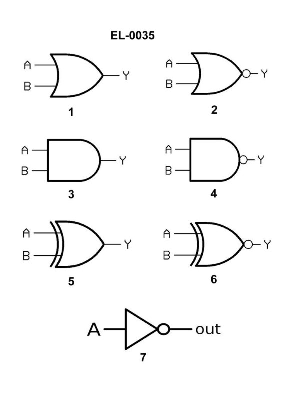
ANOR gate
BAND gate
CNAND gate
DXOR gate
AI Explanation
The correct answer is C) NAND gate. The NAND gate is symbolized in figure "4" of the illustration EL-0035. This is because the NAND gate is the logical inverse of the AND gate, meaning that the output is only low (or 0) when all the inputs are high (or 1). This is the same logic pattern represented in the illustration. The other options are incorrect because they do not match the logic pattern shown in the figure. A NOR gate has a different logic pattern, an AND gate would have a different symbol, and an XOR gate also has a different logic pattern.
Related Questions
Q392:You are in the planning stages of making up a portable cable to be used for tran...
Q253:If the motor shown in the illustration will not start when the "off-run" switch ...
Q285:As shown in figure "A" of the illustration, what is the purpose of the "test but...
Q518:What is a disadvantage to the use of high voltage systems onboard ship?
Q480:On a vessel with turbo-electric drive, which of the following conditions would i...
Ready to test your knowledge?
Take a Electricity & Electronics - Assistant Engineer Practice ExamOfficial Resources
Pass Your Coast Guard Licensing Exams!
Study offline, track your progress, and simulate real exams with the Coast Guard Exams app