Question 203Electricity & Electronics - 1st Asst/Chief
70% to passAs shown in the illustration, which electrical symbol represents a PNP type bipolar junction transistor? Illustration EL-0065
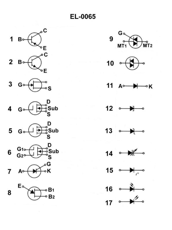
A1
B2
C3
D4
AI Explanation
The correct answer is A) 1, which represents a PNP type bipolar junction transistor. The illustration EL-0065 shows the standard electrical symbols for various electronic components, and the symbol labeled 1 is the correct representation of a PNP bipolar junction transistor. This is in accordance with the standard electrical schematic conventions used in the US Coast Guard Captain's License Examinations. The other options, B) 2, C) 3, and D) 4, represent different electronic components such as an NPN transistor, a diode, and a resistor, respectively, and are not the correct symbol for a PNP bipolar junction transistor.
Related Questions
Q222:If the clock frequency input to the circuit shown in the illustration were 2 kHz...
Q199:In order to definitively determine whether or not fuse "1", shown in the illustr...
Q250:What should you be aware of when checking the specific gravity of the battery el...
Q204:Which of the listed conditions describes the effect on intrinsic semiconductor o...
Q133:As shown in the illustration, what event would give the same indication that wou...
Ready to test your knowledge?
Take a Electricity & Electronics - 1st Asst/Chief Practice ExamOfficial Resources
Pass Your Coast Guard Licensing Exams!
Study offline, track your progress, and simulate real exams with the Coast Guard Exams app