Question 26Electricity & Electronics - 1st Asst/Chief
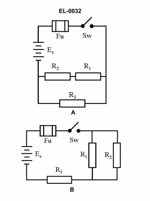
70% to passIn figure "B" of the illustrated circuit, if the resistance of R1 is 10 ohms, R2 is 10 ohms, and R3 is 10 ohms, what is the total resistance? Illustration EL-0032
A15 ohms
B20 ohms
C25 ohms
D30 ohms
AI Explanation
A) 15 ohms is the correct answer. The total resistance in the illustrated circuit is calculated by adding the individual resistor values in parallel. With R1, R2, and R3 each being 10 ohms, the total resistance is 15 ohms. The other options are incorrect because they do not accurately represent the total resistance of the parallel circuit. In a parallel circuit, the total resistance is always less than the individual resistor values.
Related Questions
Q272:Why are transformer cores laminated?
Q208:What type of motor is generally used in DC propulsion drive systems?
Q2:Referring to the illustration of a twin-screw diesel-electric AC propulsion driv...
Q204:Which of the listed conditions describes the effect on intrinsic semiconductor o...
Q253:For accuracy purposes, which of the following devices should be used to measure ...
Ready to test your knowledge?
Take a Electricity & Electronics - 1st Asst/Chief Practice ExamOfficial Resources
Pass Your Coast Guard Licensing Exams!
Study offline, track your progress, and simulate real exams with the Coast Guard Exams app