Question 198Electricity & Electronics - QMED
70% to passIf it is required that the coils 'R1-R2-R3' in the indicator of figure "A", turn opposite to those in the transmitter, as shown in the illustration, what action should be taken? Illustration EL-0092
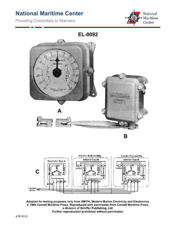
AInterchange leads 'R1' and 'R3'.
BInterchange leads 'R2' and 'R3'.
CReverse the 60 Hz supply connections to 'S1' and 'S2'.
DNo action is needed.
AI Explanation
The correct answer is A) Interchange leads 'R1' and 'R3'. The reasoning is that for the indicator in figure "A" to turn in the opposite direction of the transmitter, the coils 'R1-R2-R3' in the indicator need to be connected in the reverse order compared to the transmitter. Interchanging the leads 'R1' and 'R3' will achieve this, as it will reverse the direction of the coils in the indicator. The other options are incorrect because B) interchanging 'R2' and 'R3' would not reverse the direction, C) reversing the 60 Hz supply connections would not address the issue with the coil order, and D) some action is needed to correct the coil orientation.
Related Questions
Q271:How may propulsion DC motor brush pressures be calculated? Q517:When would be the safest time to close the ship's main switchboard "shore power"... Q304:As shown in the illustration, which of the following conditions will occur as a ... Q156:What is an ohmmeter used to measure? Q326:To limit the current flow through a DC voltmeter to as low a value as possible, ...
Ready to test your knowledge?
Take a Electricity & Electronics - QMED Practice ExamOfficial Resources