Question 354Electricity & Electronics - QMED
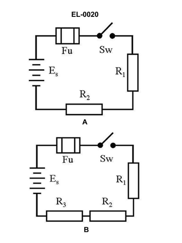
70% to passAs shown in figure "A" of the illustration if the applied voltage is 12 VDC, the resistance of R1 is 10 ohms, and R2 is 10 ohms what is the current flowing through R1 when the switch is closed? Illustration EL-0020
A0.6 amp
B0.833 amp
C1.2 amps
D2.4 amps
AI Explanation
The correct answer is A) 0.6 amp. According to Ohm's law, the current flowing through a resistor is equal to the applied voltage divided by the resistance of the resistor. In this case, the applied voltage is 12 VDC, and the resistance of R1 is 10 ohms. Plugging these values into the formula, we get: I = V/R = 12 V / 10 ohms = 1.2 amps. The other answer choices are incorrect because: B) 0.833 amp is incorrect as it does not match the calculation using Ohm's law. C) 1.2 amps is incorrect as it is the total current in the circuit, not the current flowing through R1. D) 2.4 amps is incorrect as it is double the correct answer, which does not match the given information.
Related Questions
Q523:As load is added to a DC shunt motor, how will the motor respond? Q225:Assuming a standard 60 Hz input to the circuit shown in the illustration, what w... Q331:Which of the illustrated schematic symbols represents the type of switch picture... Q193:You are attempting to parallel two AC generators and the synchroscope pointer st... Q102:Which of the formulas listed is correct for determining power?
Ready to test your knowledge?
Take a Electricity & Electronics - QMED Practice ExamOfficial Resources