Question 358Electricity & Electronics - QMED
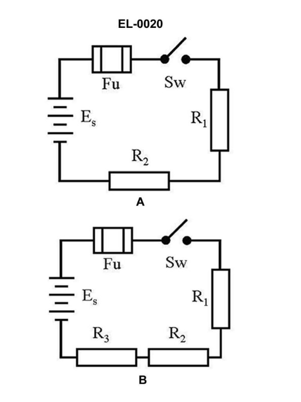
70% to passWhat is the voltage across 'R1' of figure "B" of the illustrated circuit with the switch closed if the applied voltage is 24 volts and resistance of R1 is 3 ohms, R2 is 4 ohms, and R3 is 5 ohms, respectively? Illustration EL-0020
A2 volts
B6 volts
C8 volts
D10 volts
AI Explanation
The correct answer is B) 6 volts. To find the voltage across R1, we can use the formula for voltage division: V1 = (R1 / (R1 + R2 + R3)) * Vapp, where V1 is the voltage across R1, R1 is the resistance of R1, R2 is the resistance of R2, R3 is the resistance of R3, and Vapp is the applied voltage. Plugging in the given values, we get: V1 = (3 / (3 + 4 + 5)) * 24 = 6 volts. The other options are incorrect because they do not correctly apply the voltage division formula to the given circuit and resistor values.
Related Questions
Q147:By what means is the burning of controller contacts due to arcing, when opening,... Q408:Which of the listed types of lighting fixtures does the diagram shown in figure ... Q472:Which of the following statements describes the difference between the primary w... Q96:AC circuits can possess characteristics of resistance, inductance, and capacitan... Q273:To effectively clean a commutator in good physical condition, what should be use...
Ready to test your knowledge?
Take a Electricity & Electronics - QMED Practice ExamOfficial Resources